Feedback Feedback
|
Table Of Contents
About These Release Notes (MGX 1.2.20)
VISM-PR to RPM-PR Connectivity
Configuring the Cell Bus Clock (CBC) Rate
LDP on RPM Running MGX Release 1.2.02 and Cisco IOS Release 12.2(8)T1
Multi-LVC on RPM Running MGX Release 1.2.02 and Cisco IOS Release 12.2(8)T1
Bypass Feature for RPM in Cisco IOS Release 12.2(4)T
Features Not Supported in This Release
Special Upgrade Procedure for Cisco IOS Release 12.1(5.3)T_XT
CLI Modifications in the MGX Release 1.2.20
CWM Recognition of RPM-PR and MGX-RPM-128M/B Back Cards
RPM/B and RPM-PR Front Card Resets on the Back Card Removal
RPM/B and RPM-PR Back Ethernet Card Support
MGX-RPM-128M/B Ethernet Back Card Support
RPM/B and RPM-PR Limitations and Restrictions (MGX Release 1.2.20)
Open Caveats in Release 12.2.15T
Resolved Caveats in Release 12.2.15T
RPM Boot File and Firmware File Names and Sizes
Special Installation and Upgrade Requirements
Cisco IOS Release Compatibility Information
About the Cisco IOS 12.2(15)T Release
About the Cisco IOS 12.2(11)T1 Release
About the Cisco IOS 12.2(8)T4 Release
About the Cisco IOS 12.2(8)T1 Release
About the Cisco IOS 12.2(4)T3 Release
About the Cisco IOS 12.2(4)T1 Release
About the Cisco IOS 12.2(4)T Release
About the Cisco IOS 12.2(2)T2 and 12.2(2)T3 Release
About the Cisco IOS 12.1(5.3)T_XT Release
Problems Fixed with Cisco IOS 12.1(5.3)T_XT
Upgrading from an MGX-RPM-128M/B Card to an RPM-PR Card
Upgrade Procedures for RPM Cards in MGX Release 1 (PXM1) Switches
Upgrading RPM Runtime Software
Upgrade Procedure for Boot Software and Runtime Software for Non-Redundant Cards
Upgrading RPM Boot Software and Runtime Software for 1:N Redundancy
Using XModem to Download Flash to RPM Cards
Historical Information From 1.2.x Baseline
Problems Fixed in Release 1.2.11
Problems Fixed in Release 1.2.00
Problems Fixed in Release 1.2.02
Problems Fixed in Release 1.2.01
Problems Fixed in Release 1.2.00
About These Release Notes (MGX 4.0.00)
RPM Image Directory Change From E:RPM to C:/FW
Using the switchredcd Command with RPM-PR Cards to Switch from Active to Standby Card
VISM-PR to RPM-PR Connectivity
Configuring the Cell Bus Clock (CBC) Rate
LDP on RPM-PR in MGX 8850 and MGX 8950
Multi-LVC on RPM in MGX 8850 and MGX 8950 Release 2.1.76 Running Cisco IOS Release 12.2(8)T1
Bypass Feature for RPM in Cisco IOS Release 12.2(4)T
Features Not Supported in This Release
CLI Modifications in MGX Release 4.0.00
CWM Recognition of RPM-PR Back Card
RPM Front Card Resets on the Back Card Removal
RPM-PR Back Ethernet Card Support
RPM-PR Limitations and Restrictions (PXM45 and PXM1E)
Problems Fixed in This Release
Open Caveats in Release 12.2.15T
RPM Boot File and Firmware File Names and Sizes
Special Installation and Upgrade Requirements
Cisco IOS Release Compatibility Information
About the Cisco IOS 12.2(15)T Release
About the Cisco IOS 12.2(11)T1 Release
About the Cisco IOS 12.2(8)T4 Release
About the Cisco IOS 12.2(8)T1 Release
About the Cisco IOS 12.2(4)T3 Release
About the Cisco IOS 12.2(4)T1 Release
About the Cisco IOS 12.2(4)T Release
Upgrading RPM Runtime Software
Upgrade Procedure for Boot Software and Runtime Software for Non-Redundant Cards
Upgrading RPM-PR Boot Software and Runtime Software for 1:N Redundancy
Using XModem to Download Flash to RPM Cards
Historical Information From 3.x Baseline
Problems Fixed in Release 3.0.00
Historical Information From 2.1.7x Baseline
Anomalies Resolved in Release 2.1.79
Anomaly Status Changes in 2.1.79
Anomaly Status Changes in Release 2.1.76
Anomalies Resolved in Release 2.1.75
Anomaly Status Changes in Release 2.1.75
Anomalies Resolved in Release 2.1.70
Anomaly Status Changes in Release 2.1.70
Cisco MGX 8850 (PXM45) Multiservice Switch Release 4
Cisco MGX 8850 (PXM1E) Multiservice Switch Release 4
Cisco MGX 8950 Multiservice Service Release 4
Cisco MGX 8830 Multiservice Switch Release 4
Cisco WAN Switching Software Release 9.4
MGX 8850 (PXM1) Edge Concentrator Release 1.2.20
MGX 8250 Edge Concentrator Release 1.2.20
MGX 8230 Edge Concentrator Release 1.2.20
Obtaining Technical Assistance
Obtaining Additional Publications and Information
Release Notes for Cisco MGX Route Processor Module (RPM/B and RPM-PR) for MGX Release 1.2.20 and MGX Release 4.0.00
Contents
About These Release Notes (MGX 1.2.20)
Cisco documentation and additional literature are available in a CD-ROM package, which ships with your product. The Documentation CD-ROM, a member of the Cisco Connection Family, is updated monthly. Therefore, it might be more current than printed documentation. To order additional copies of the Documentation CD-ROM, contact your local sales representative or call customer service. The CD-ROM package is available as a single package or as an annual subscription.
Note that for Release 1.2.20, the user documentation (command reference, overview, and installation and configuration guides) were not updated. Use the Release 1.1.3 and 1.2.10 documents in addition to this release note.
Product documentation for MGX 8850 is available at the following URL:
http://www.cisco.com/univercd/cc/td/doc/product/wanbu/mgx8850/1_1_31/index.htmProduct documentation for MGX 8250 is available at the following URL: http://www.cisco.com/univercd/cc/td/doc/product/wanbu/mgx8250/1_1_31/index.htm
Product documentation for MGX 8230 is available at the following URL:
http://www.cisco.com/univercd/cc/td/doc/product/wanbu/mgx8230/1_1_31/index.htmProduct documentation for VISM 3.0(0) is available at the following URLs:
http://www.cisco.com/univercd/cc/td/doc/product/wanbu/mgx8850/Product documentation for RPM 1.1 and 1.2.20 is available at the following URLs:
http://www.cisco.com/univercd/cc/td/doc/product/wanbu/mgx8850/rpm/index.htm
http://www.cisco.com/univercd/cc/td/doc/product/wanbu/mgx8250/rpm/index.htm
http://www.cisco.com/univercd/cc/td/doc/product/wanbu/mgx8230/rpm/index.htmIf you are reading Cisco product documentation on the World Wide Web, you can submit comments electronically. Click Feedback in the toolbar, select Documentation, and click Enter the feedback form. After you complete the form, click Submit to send it to Cisco. We appreciate your comments.
Special Notes
Please refer to the this Web page for the latest updates on software and firmware issues.
http://www.cisco.com/cgi-bin/Software/Iosplanner/Planner-tool/printsa.pl?get_crypto=&data_from=&hardware_name=&software_name=&release_name=12.2.15T&majorRel=12.2&state=:RL&type=Early%20Deployment&file=12.2.15T.c.html
New Features
RPM in MGX 8800 Release 1.2.20 supports all new and existing features introduced in the Release 1.2.x baseline. There are no new features for RPM implementations using IOS Release 12.2(15)T.
Previously Released Features
Automatic Cell Bus Clocking
To implement automatic cell bus clocking, a new -autoClkMode option has been added to the xcnfcbclk command. The default is disabled for backward compatibility. When the feature is enabled by entering the xcnfcbclk -autoClkMode enable command, the PXM scans the whole shelf to see whether there are any two RPMs residing on the same cell bus and changes that cell bus to be running at 42MHz clock rate. The clock rate for the rest of the cell buses are not changed. The active PXM updates the disk DB and sends the update to the standby PXM.
When the feature is enabled, the user will not be able to configure the cell bus clock rate manually for any of the cell buses. When disabled with xcnfcbclk -autoClkMode disable command, the PXM will not change the clock rate for any of the cell bus, but will still update the disk DB and send the update to the standby PXM.
Note
The command to enable or disable the feature is on a per shelf basis.
Note
Note
The output of dspcbclk command changes to reflect this new feature. A new column is added to show whether the feature is enabled or disabled on the cell buses.When the feature is enabled and an RPM card is inserted, the PXM checks whether the card that resides next to it on the same cell bus is also an RPM card. If both cards are RPM cards, and neither of them is in failed, reserved, unknown, self-test-fail, or no-card state, the cell bus clock rate is automatically set to 42MHz.
Conversely, when the feature is enabled, and an RPM card with a cell bus clock rate of 42MHz is removed or fails, the PXM sets the cell bus to 21MHz, as shown in the follwoing example.
mgx574.1.7.PXM.a > dspcbclkCellBus Rate (MHz) Slot AutoClkMode--------------------------------------------------CB1 21 1, 2 disableCB2 21 3, 4 disableCB3 21 5, 6 disableCB4 21 17 - 22 disableCB5 21 9, 10 disableCB6 21 11, 12 disableCB7 21 13, 14 disableCB8 21 25 - 30 disablemgx574.1.7.PXM.a > cnfcbclk 1 42WARNING: Certain Service Modules will not operate at the clock rate you specified.Please check the Service Modules in the slots where the Cell Bus clock rate iseffected by this command.mgx574.1.7.PXM.a > cnfcbclk 5 42WARNING: Certain Service Modules will not operate at the clock rate you specified.Please check the Service Modules in the slots where the Cell Bus clock rate iseffected by this command.mgx574.1.7.PXM.a > dspcbclkCellBus Rate (MHz) Slot AutoClkMode--------------------------------------------------CB1 42 1, 2 disableCB2 21 3, 4 disableCB3 21 5, 6 disableCB4 21 17 - 22 disableCB5 42 9, 10 disableCB6 21 11, 12 disableCB7 21 13, 14 disableCB8 21 25 - 30 disablemgx574.1.7.PXM.a > xcnfcbclkNot enough arguments (?)xcnfcbclk "-cb <cellBus> -rate <clockRate> -autoClkMode <autoClkEnable>"-cb <cellBus>, where cellBus is a string CB1..CB8-rate <clockRate>, where clockRate is 21 or 42 (MHz)-autoClkMode <autoClkEnable>, where autoClkEnable is enable or disablemgx574.1.7.PXM.a > xcnfcbclk -autoClkMode enablemgx574.1.7.PXM.a > dspcbclkCellBus Rate (MHz) Slot AutoClkMode--------------------------------------------------CB1 42 1, 2 enableCB2 21 3, 4 enableCB3 21 5, 6 enableCB4 21 17 - 22 enableCB5 21 9, 10 enableCB6 42 11, 12 enableCB7 21 13, 14 enableCB8 21 25 - 30 enableVISM-PR to RPM-PR Connectivity
VISM Release 3.0 introduces the new VISM-PR front cards for Cisco MGX Release 1.2.10 (and Cisco IOS Release 12.2(8)T4). The new VISM-PR-8E1 and VISM-PR-8T1 cards work in the MGX 8230, MGX 8250, and MGX 8850 Release 1 switches, in combination with the PXM1 Processor Module card. The VISM-PR card support 144 channels when used with the G.723.1 codec, whereas the current VISM card support supports 64 channels with the G.723.1 codec.
Setting connections between a VISM-PR card and a RPM-PR card in your MGX8000 Series switch chassis requires that you use the new VBR (NRT)3 connection type.
For more information, refer to the Cisco VISM Installation and Configuration Guide.
Configuring the Cell Bus Clock (CBC) Rate
As of Cisco MGX Release 1.2.10 and Cisco IOS Release 12.2(8)T4), when two RPM-PR cards are on the same cell bus, that is, they occupy adjacent slots (for example, slots 1 and 2 or slots 3 and 4), the cell bus clock (CBC) rate should be manually set to 42MHz. Correspondingly, if there is only one RPM on the cell bus, the clock should be at the default value of 21 MHz.
If, for any reason, one of the adjacent RPM-PRs goes to Failed or Empty state, the CBC for that cell bus must be reconfigured for the Traffic Shaping to work correctly on the active RPM. On MGX 1 switches with Release 1.2.10, the 42MHz to 21 MHz change must be explicitly performed using the cnfcbclk command. Use the dspcbclk command from the PXM1 to confirm the cell bus clock rate.
The following screen output displays the use of the cnfcbclk and dspcbclk commands used to change the clock on cell bus 1 (for slots 1 and 2) from 21 MHz to 42 MHz and confirm the change.
PXM> dspcbclkCellBus Rate (MHz) Slot-------------------------------CB1 21 1, 2CB2 21 3, 4CB3 21 5, 6CB4 21 17 - 22CB5 21 9, 10CB6 21 11, 12CB7 21 13, 14CB8 21 25 - 30PXM> cnfcbclk CB1 42WARNING: Certain Service Modules will not operate at the clock rate you specified.Please check the Service Modules in the slots where the Cell Bus clock rate is effected by this commandmgx3.1.7.PXM.a > dspcbclkCellBus Rate (MHz) Slot-------------------------------CB1 42 1, 2CB2 21 3, 4CB3 21 5, 6CB4 21 17 - 22CB5 21 9, 10CB6 21 11, 12CB7 21 13, 14CB8 21 25 - 30RPM makes use of idle cells for Traffic Shaping and Scheduling. If there are two RPMs in adjacent slots on the same cell bus and one of the RPMs is put into a Failed state by the PXM, while that card is actually alive, then the "Failed" RPM must stop sending idle cells to avoid impacting the Traffic Shaping on the adjacent functional RPM. The command that implements the RPM support for this feature is rpm-auto-cbclk-change.
rpm-auto-cbclk-change enables the RPM to stop sending idle cells in the event of being put into a "FAILED" state by the PXM and thus prevent an impact on the Traffic Shaping on an adjacent functional RPM.
no rpm-auto-cbclk-change which disables the feature to stop sending of idle cells if the RPM is put into a FAILED state. This command may be used if Traffic Shaping is not required.
The following screen output displays an example of the rpm-auto-cbclk-change command.
RPM-11#config terminalEnter configuration commands, one per line. End with CNTL/Z.RPM-11(config)#int sw1RPM-11(config-if)#rpm-auto-cbclk-changeRPM-11(config-if)#endRPM-11#write memBuilding configuration...[OK]RPM-11#show run int sw1Building configuration...Current configuration :142 bytes!interface Switch1no ip addressno atm ilmi-keepaliverpm-auto-cbclk-changeswitch autoSynch offend! rpm_tag_id Apr 04 2002 02:49:04If Traffic Shaping is not a requirement, enter the no rpm-cbclk-change command, either manually or during card configuration. The following screen output displays an example of the no rpm-auto-cbclk-change command.
RPM-11#config terminalEnter configuration commands, one per line. End with CNTL/Z.RPM-11(config)#int sw1RPM-11(config-if)#no rpm-auto-cbclk-changeRPM-11(config-if)#endRPM-11#write memBuilding configuration...[OK]RPM-11#show run int sw1Building configuration...Current configuration :145 bytes!interface Switch1no ip addressno atm ilmi-keepaliveno rpm-auto-cbclk-changeswitch autoSynch offend! rpm_tag_id Apr 04 2002 02:49:57
Note
LDP on RPM Running MGX Release 1.2.02 and Cisco IOS Release 12.2(8)T1
The MPLS label distribution protocol (LDP), as standardized by the Internet Engineering Task Force (IETF) and as enabled by Cisco IOS software, allows the construction of highly scalable and flexible IP Virtual Private Networks (VPNs) that support multiple levels of services.
LDP provides a standard methodology for hop-by-hop or dynamic label distribution in an MPLS network by assigning labels to routes that have been chosen by the underlying Interior Gateway Protocol (IGP) routing protocols. The resulting labeled paths, called label switch paths (LSPs), forward label traffic across an MPLS backbone to particular destinations. These capabilities enable service providers to implement Cisco's MPLS-based IP VPNs and IP+ATM services across multivendor MPLS networks.
From a historical and functional standpoint, LDP is a superset of Cisco's pre-standard Tag Distribution Protocol (TDP), which also supports MPLS forwarding along normally routed paths. For those features that LDP and TDP share in common, the pattern of protocol exchanges between network routing platforms is identical. The differences between LDP and TDP for those features supported by both protocols are largely embedded in their respective implementation details, such as the encoding of protocol messages, for example.
This software release of LDP provides the means for transitioning an existing network from a TDP operating environment to an LDP operating environment. Thus, you can run LDP and TDP simultaneously on any given router platform. The routing protocol that you select can be configured on a per-interface basis for directly-connected neighbors and on a per-session basis for non-directly-connected (targeted) neighbors. In addition, a label switch path (LSP) across an MPLS network can be supported by LDP on some hops and by TDP on other hops.
MPLS LDP offers the following features:
•
•
•
Multi-LVC on RPM Running MGX Release 1.2.02 and Cisco IOS Release 12.2(8)T1
This feature enables support for initiation of multiple label switched paths (LSPs) per destination on the RPM. Different label switched paths are established for different class of services. This feature enables interface level queueing rather than per-vc level on the RPM based on MPLS class of service policy. With Multi-LVC support, customers can deploy IP VPN services with Class of Service SLAs.
Bypass Feature for RPM in Cisco IOS Release 12.2(4)T
Note
RPM cards have a maximum storage of 128 KB for the NVRAM. This size limitation creates a problem for customers with large configurations, who find it impossible to store the complete configuration in the NVRAM, even with compression enabled.
In order to support storage of large configuration files, a new bypass feature is now available in the 12.2(4)T IOS Release. With the bypass feature enabled, the enhanced "write memory" is used to bypass the NVRAM and save the configuration on:
•
Where ## represents the zero-padded slot number in which the RPM card is seated in the MGX chassis.
To enable the bypass feature, issue the command rpmnvbypass from the IOS run time image—not in the IOS boot image.
To disable the bypass feature, enter the command no rpmnvbypass.
To verify that the bypass feature is either enabled or disabled, enter the show running-configuration command. If the bypass feature is enabled, rpmnvbypass is seen on the display. If it is not seen, the feature is not enabled.
Note
Table 1 contains cautions important to the successful usage of the bypass feature.
Example 1 through Example 5 illustrate how the bypass feature is enabled and disabled, and how to validate each of these actions from the configuration display.
Example 1 Running configuration without the bypass feature enabled
rpm_slot02#show running-configBuilding configuration...Current configuration : 470 bytes!version 12.2service timestamps debug uptimeservice timestamps log uptimeno service password-encryption!hostname rpm_slot02!boot system c:rpm-js-mz.<new_rel>enable password cisco!ip subnet-zero!!!!interface Switch1no ip addressno atm ilmi-keepaliveswitch autoSynch off!ip classlessno ip http serverip pim bidir-enable!!snmp-server community public ROsnmp-server community private RW!!line con 0line aux 0line vty 0 4no login!endExample 2 Enable the bypass feature (rpmnvbypass)
rpm_slot02#rpm_slot02#configure terminalEnter configuration commands, one per line. End with CNTL/Z.rpm_slot02(config)#rpmnvbypassThe "boot config" statement has been (re)added to yourrunning configuration. Do not remove it else risk notusing the nvbypass featurerpm_slot02(config)#endrpm_slot02#Example 3 Running configuration with bypass feature enabled (note rpmnvbypass at end of output)
rpm_slot02#show running-configBuilding configuration...Current configuration : 515 bytes!version 12.2service timestamps debug uptimeservice timestamps log uptimeno service password-encryption!hostname rpm_slot02!boot system c:rpm-js-mz.<new_rel>boot config c:auto_config_slot02 <==== Line added as per output aboveenable password cisco!ip subnet-zero!!!interface Switch1no ip addressno atm ilmi-keepaliveswitch autoSynch off!ip classlessno ip http serverip pim bidir-enable!!snmp-server community public ROsnmp-server community private RW!!line con 0line aux 0line vty 0 4no login!rpmnvbypassendExample 4 Disable the bypass feature (no rpmnvbypass)
rpm_slot02#configure terminalEnter configuration commands, one per line. End with CNTL/Z.rpm_slot02(config)#no rpmnvbypassrpm_slot02(config)#endrpm_slot02#Example 5 Running configuration after the bypass feature is disabled
rpm_slot02#show running-configBuilding configuration...Current configuration : 503 bytes!version 12.2service timestamps debug uptimeservice timestamps log uptimeno service password-encryption!hostname rpm_slot02!boot system c:rpm-js-mz.<new_rel>boot config c:auto_config_slot02enable password cisco!ip subnet-zero!!!!interface Switch1no ip addressno atm ilmi-keepaliveswitch autoSynch off!ip classlessno ip http serverip pim bidir-enable!!snmp-server community public ROsnmp-server community private RW!!line con 0line aux 0line vty 0 4no login!endrpm_slot02#Features Not Supported in This Release
The following features are not supported on RPM:
•
•
RPM Redundancy Support
RPM 1:N redundancy is used to switch configuration and traffic from one RPM card to another. The main benefits are:
•
•
•
SNMP MIB
SNMP MGX Release 1 MIB are provided with the delivery of this release. The MIB is in standard ASN.1 format and is located in the same directory within the release bundle on CCO. These files may be compiled with most standards-based MIB compilers. The tar file for MIB contains the file release notes that contains the MIB release notes.
For changes in this MIB from the previous release, please refer to the MIB release notes.
Note
Notes and Cautions
The following notes and cautions should be reviewed before using this release.
Special Upgrade Procedure for Cisco IOS Release 12.1(5.3)T_XT
Use the following procedure when upgrading from your current RPM/IOS runtime image 12.1(5.3)T_XT and MGX version for MGX Release 1.2.02 and 1.2.10:
Step 1
Step 2
a.
b.
c.
For more detail on the MGX upgrade procedures, refer to the Release Notes for Cisco MGX 8230, MGX 8250, and MGX 8850 (PXM1), Software Version 1.2.10.
UPC Connection Parameters
In Release 1.1.40 and higher, the default PCR is 50 cps, and the default for policing is "enabled." These settings are insufficient for running RPM ISIS protocol over the connection, and with such settings, the ISIS protocol will fail. The PCR value needs to be increased, depending upon the number of interfaces configured for ISIS on the RPM.
Depending upon your connection type, you can use the following CLIs to modify the PCR parameter.
•
•
•
•
Booting the RPM-PR
Refer to Chapter 5, "Configuring the MGX RPM" in the Cisco MGX Route Processor Module Installation and Configuration Guide, Release 1.1 for complete details on configuring the RPM-PR cards. A summary of the booting and upgrading procedures is presented here for your convenience.
When the RPM-PR is booted, the boot image must be the first file in the bootflash. If the bootflash does not have a valid boot image as a first file, the card may not be able to boot.
You can reboot the RPM-PR from the PXM by entering the command resetcd <card_number> from the switch CLI, where card_number is the slot number of the RPM-PR that is being rebooted.
Note
Also, you can reboot the RPM-PR from the RPM-PR using the RPM-PR console port and entering the reload command.
Each time you turn on power to the RPM-PR, by inserting the RPM-PR into the MGX 8850, it goes through the following boot sequence:
1.
2.
The source of the Cisco IOS image is determined by the configuration register setting. To verify this setting, you can enter either the show version or show bootvar command. (Refer to the "Viewing the Hardware Configuration" section of the Cisco MGX Route Processor Module Installation and Configuration Guide, Release 1.1.
a.
b.
3.
a.
b.
c.
4.
5.
If you want to load from a specific configuration file, you should enter either the boot config bootflash:<config_file> command or the boot config c:<config_file> command.
6.
The first time you boot the RPM-PR, configure the RPM-PR interfaces and save the configuration to a file in NVRAM. Then follow the procedure described in "Initializing the RPM-PR Card." For information on the Cisco IOS instructions, refer to Appendix C, "IOS and Configuration Basics"of the Cisco MGX Route Processor Module Installation and Configuration Guide, Release 1.1 .
RPM-PR Bootflash Precautions
The RPM-PR bootflash is used to store boot image, configuration and "run time" files. The Flash stores and accesses data sequentially, and the RPM-PR boot image must be the first file stored to successfully boot the card. Erasing the boot image or moving it from the first position on the Flash will cause the card to not boot.
The RPM boot image, which comes loaded on the Flash, will work for all RPM IOS images. Therefore, there is no reason to ever delete or move the factory installed boot image.
Caution
In order to avoid this unnecessary failure, requiring card servicing, you should
•
•
•
As long as the boot file remains intact in the first position on the flash, the RPM will successfully boot.
CLI Modifications in the MGX Release 1.2.20
There are no new or modified RPM/B or RPM-PR CLI commands for MGX Release 1.2.20.
Limitations and Restrictions
CWM Recognition of RPM-PR and MGX-RPM-128M/B Back Cards
CWM does not distinguish between the Ethernet back card versions installed with the MGX-RPM-128M/B or RPM-PR. There is no functionality difference.
RPM/B and RPM-PR Front Card Resets on the Back Card Removal
The RPM front card may reset on an MGX 8250 and MGX8850 switches with PXM1 as controller card, when the ethernet back card is removed or inserted.
This reset problem can be easily avoided if "shut" interface is executed before the removal of the back card.
RPM/B and RPM-PR Back Ethernet Card Support
For Ethernet connectivity with the RPM-PR, the model "/B" four-port Ethernet back card is required (order number: MGX-RJ45-4E/B).
MGX-RPM-128M/B Ethernet Back Card Support
The model "/B" four-port Ethernet back card can be used with the MGX-RPM-128M/B module only in combination with IOS 12.2(2)T2 or higher. The model "/B" back card will not work on the MGX-RPM-128M/B with earlier versions of the IOS.
The order number is order number: MGX-RJ45-4E/B.
Older back cards can be used with any version of the IOS.
model "/B" back card
12.2(2)T2
earlier back card models
Min. IOS for MGX-RPM-128M/B on MGX 8250 is 12.0(7)T
RPM/B and RPM-PR Limitations and Restrictions (MGX Release 1.2.20)
The RPM/B and RPM-PR limitations and restrictions that apply to this release are as follows:
•
•
•
•
•
•
•
•
•
•
•
•
•
•
•
•
•
Open Caveats in Release 12.2.15T
Table 2 lists the open caveats in Cisco IOS Release 12.2.15T.
Table 2 Open Caveats in Cisco IOS Release 12.2.15T
CSCec16481
Symptom:
A Cisco device running Internetwork Operating System (IOS) and enabled for the Open Shortest Path First (OSPF) Protocol is vulnerable to a Denial of Service (DoS) attack from a malformed OSPF packet. The OSPF protocol is not enabled by default.
Conditions:
The vulnerability is only present in IOS release trains based on 12.0S, 12.2, and 12.3. Releases based on 12.0, 12.1 mainlines and all IOS images prior to 12.0 are not affected. Refer to the Security Advisory for a complete list of affected release trains.
Workaround:
Further details and the workarounds to mitigate the effects are explained in the Security Advisory which is available at the following URL:
http://www.cisco.com/warp/public/707/cisco-sa-20040818-ospf.shtml.
CSCdz79827
Symptom:
While performing MIB walk on the whole CISCO-IP-STAT-MIB MIB, cipPrecedenceEntry goes through a loop.
Conditions:
While performing MIB walk on CISCO-IP-STAT-MIB MIB, cipPrecedenceEntry loops around and does not exit out of the mib walk.
Workaround: None
CSCdz87255
Symptom:
RPM-XF resets if an incorrect name is specified in the "mic rel pxf " command
Conditions:
In the "microcode reload pxf" command, the file name specified is not present in the "C:FW" directory on the PXM.
Workaround:
Make sure the correct filename is specified.
CSCea59731
Symptom:
When querying on the ifName , the output does not follow the desired format.As a result , SNMP dependent tools will fail due to unexpected result.
Conditions:
This symptom is observed while issuing snmpwalk on the node for ifName.
Workaround: None
CSCea77841
Symptom:
Trace back error: "rpm_red_copy_file_to_dev: copy failed" observed after RPM-PR card reload.
Conditions:
Not enough free space left on the bootflash.
Workaround: None
CSCdx04380
Symptom:
Status field of an RPM interface shows unknown(3).Database schema says it can be onle 1 or 2
Workaround: None
CSCdz56476
Symptom:
Traceback errors - "%SYS-2-BADSHARE: Bad refcount in retparticle" were observed on RPM-PR (Route Processor Module)
Conditions:
After clearing the arp table and reseting the IXIA FE ports, traceback error messages appeared on the console.
Workaround: None
CSCea22766
Symptom:
PXM1 Controller card got reset due to starved tChStats task.
Conditions:
While connection proxy and show command scripts were running in the back ground and lots of BGP routes were also being updated, during this setup, PXM1 controller card got reset. PXM1 logs suggested tChStats task was starved, which caused tRootTask to reset PXM1.
Workaround: None
CSCea26869
Symptom:
IPC Low Buffer traceback observed on PE.
Conditions:
After running the multiple show commands and injecting & withdrawing VRF routes from CE, PE kept getting IPC low buff trace back messages.
Workaround: None
CSCdz32991
Symptom:
RPM-PR on the MGX8850 with PXM45 as controller card, occasionally drops ping packets due to CRC error.
Conditions:
RPM-PR on the MGX8850 with PXM45 as controller card, occasionally drops ping packets due to CRC error. The ping packets came from the 7200 router on BPX.
Workaround:
None
CSCdz33457
Symptom:
RPM-PR card reloaded after reporting Traceback messages on console; also generated crashinfo file.
Condition:
This happened after "ip rtp compression-connection 300" command was issued on the RPM-PR card, which resulted in reload/reset of the said card.
Workaround:
None
CSCdz48135:
Symptom:
On an RPM-PR running IOS 12.2(8)T4 / 12.2(13)T, service policy command can be configured under the PVC on a switch1 interface.
Conditions:
Service policy command can be configured under the PVC on a subinterface for the Switch1 interface on RPM-PR installed in MGX8230 / MGX8850 node (w/ PXM45 and/or PXM1E controller card). Although the service policy command is accepted, the queueing strategy remains FIFO.
Workaround:
None
Resolved Caveats in Release 12.2.15T
Table 3 lists the resolved caveats in Cisco IOS Release 12.2.15T.
Compatibility Notes
RPM Boot File and Firmware File Names and Sizes
The following table displays the RPM boot and firmware file names and sizes for this release.
Table 4 RPM Boot and Firmware File Names and Sizes
Boot File
rpm-js-mz.122-15.T
9959712
Firmware File
rpm-boot-mz.122-15.T
3188920
RPM Compatibility Matrix
IOS Version
12.1(5.3)T_XT
12.2(2)T2
12.2(4)T
CWM
10.4.01
10.4.01 Patch 1
10.5
IOS Version
12.2(4)T1
12.2(8)T11
12.2(8)T4
12.2(11)T1
12.2(11)T2
CWM
10.5.10
10.5.10 Patch 1
11.0.00
11.0.10
11.0.10 Patch 1
1 MGX 1.2.02 has also been certified with IOS 12.2(4)T3.
MGX RPM/B and RPM-PR Hardware
Table 5 shows the front card and back card compatibility for the RPM/B and RPM-PR hardware supported in this release. The table lists the card model/ name, part numbers, the minimum version and the minimum revisions of each card supported. Note that there may be more than one 800 level part numbers for the same front cards. The minimum version is identified by the last 2 digits of the 800 level numbers.
Special Installation and Upgrade Requirements
Existing customers should use the upgrade procedures Upgrade Procedures for RPM Cards in MGX Release 1 (PXM1) Switches and Historical Information From 1.2.x Baseline to upgrade. A graceful upgrade from any release previous to the current release is supported. For new customers, the image will be pre-installed and should use the PXM installation procedure to upgrade to future maintenance releases.
Cisco IOS Release Compatibility Information
This section describes the installation requirements and guidelines for RPM modules installed with this release.
All IOS firmware can be downloaded from CCO from the following location:
http://www.cisco.com/kobayashi/sw-center/sw-ios.shtml
About the Cisco IOS 12.2(15)T Release
The Cisco IOS 12.2(15)T supports existing features on the MGX-RPM-PR and MGX-RPM-128M/B cards.
About the Cisco IOS 12.2(11)T1 Release
The Cisco IOS 12.2(11)T1 supports existing features on the MGX-RPM-PR and MGX-RPM-128M/B cards.
About the Cisco IOS 12.2(8)T4 Release
The Cisco IOS 12.2(8)T4 supports existing features on the MGX-RPM-PR and MGX-RPM-128M/B cards.
About the Cisco IOS 12.2(8)T1 Release
The Cisco IOS 12.2(8)T1 supports existing features on the MGX-RPM-PR and MGX-RPM-128M/B cards and the CBC clock rate configuration feature described in "Features Not Supported in This Release" section.
About the Cisco IOS 12.2(4)T3 Release
The Cisco IOS 12.2(4)T3 supports existing features on the MGX-RPM-PR and MGX-RPM-128M/B cards.
About the Cisco IOS 12.2(4)T1 Release
The Cisco IOS 12.2(4)T1 or higher is used with MGX Release 1.2.00. This IOS release supports new RPM features and continues to support existing features on the RPM-PR and MGX-RPM-128M/B cards.
Note that MPLS inter AS and MPLS TE are not supported features on RPM for this release.
About the Cisco IOS 12.2(4)T Release
The Cisco IOS 12.2(4)T or higher is used with MGX Release 1.1.40. This IOS release supports new RPM features and continues to support existing features on the RPM-PR and MGX-RPM-128M/B cards.
Note that MPLS inter AS and MPLS TE are not supported features on RPM for this release.
About the Cisco IOS 12.2(2)T2 and 12.2(2)T3 Release
The Cisco IOS 12.2(2)T2 and the 12.2(2)T3 Releases are used with MGX Releases 1.1.34 and 1.1.40. This IOS release does not support new RPM features, but has been tested with 1.1.34 and continues to support existing features on the RPM-PR and MGX-RPM-128M/B cards.
Please note the following anomaly in IOS Release 12.2(2)T2:
Problem Description:
Customers upgrading to 12.2(2)T2 image with RPMs might see some e-BGP sessions not coming up when the CE router is running an older version of IOS (12.0, 12.0.xT). This issue was first encountered with CE running 12.0(7)T image. In such cases, the CEs running old IOS versions were not able to create BGP sessions to PEs with the newer image (12.2(2)T2).
The issue is fixed in 12.2(2)T3. Customers who face the problems described with the 12.2(2)T2 image, may upgrade to 12.2(2)T3 image.
Symptom:
MPLS PE doesn't advertise BGP network to CE router running an older IOS image
Conditions:
A Cisco router that is running Cisco IOS Release 12.2(3.1)T or 12.2(2)T and is configured as a provider edge (PE) router may not support Label Distribution Protocol (LDP). This defect might cause the PE router not to advertise any Border Gateway Protocol (BGP) routes to a Cisco 2600 series customer edge (CE) router that is running Cisco IOS Release 12.0(18). However, the CE router will advertise routes to the PE router. Entering the neighbor ce-ipaddress don-capability-negotiate command on the PE router does not correct this defect.
Workaround:
Upgrade the CE router from Cisco IOS Release 12.0(18) to Cisco IOS Release 12.2(2)T3.
About the Cisco IOS 12.1(5.3)T_XT Release
The Cisco IOS 12.1(5.3)T_XT or higher is used with MGX Release 1.1.32 and provides support for:
•
(Note: RPM-PR is FCS with Release 1.1.32; and General Availability with Release 1.1.34.)•
•
•
Note
Problems Fixed with Cisco IOS 12.1(5.3)T_XT
Refer to the Cisco IOS Release 12.1 Release Notes at:
http://www.cisco.com/univercd/cc/td/doc/product/software/ios121/121relnt/index.htm
Upgrading from an MGX-RPM-128M/B Card to an RPM-PR Card
To replace an MGX-RPM-128M/B card with an RPM-PR card, the PXM must be running MGX Software Release 1.1.34 or later, and the RPM must be running IOS release 12.2(4)T or later. Then perform the following procedure.
Step 1
Step 2
Step 3
Step 4
Step 5
Now the RPM-PR card is ready to replace an MGX-RPM-128M/B card.
Step 6
•
•
Caution
Caution
Upgrade Procedures for RPM Cards in MGX Release 1 (PXM1) Switches
The following sections describe how to upgrade boot and runtime software on RPM cards in detail.
Upgrading RPM Boot Software
At the factory, a boot file is installed in the bootflash on the RPM card and is used to boot the card. The runtime software is updated more frequently than the boot software. However, the boot software is updated occasionally. When you are updating runtime software, check Table 4 to see if a boot software upgrade is required.
The boot software is stored in bootflash memory on the RPM card. To manage the software in bootflash, you access it as if it were a hard disk. For example, in copy and delete file commands, files are identified as bootflash:filename (which is similar to c:filename).
The following example shows a directory of bootflash contents:
Router(boot)#show flash:-#- ED --type-- --crc--- -seek-- nlen -length- -----date/time------ name1 .D config D4F7352A 40330 18 686 Jan 30 2001 18:18:41 auto_config_slot092 .D config CBF007C1 40660 9 688 Feb 22 2001 15:33:11 slot9.cnf3 .. image F596869A 2973E8 27 2452744 Feb 28 2001 03:16:05 rpm-boot-mz_002.001.070.202
Note
In the example above, the numbers in the left column indicate the order in which the RPM card will try to load software. The second column shows that the first two files are marked for deletion (D). The last column lists the names of the files stored in bootflash.
When managing the bootflash, you need to keep in mind the following:
•
•
Caution
Upgrading RPM Runtime Software
The runtime software on the RPM can be loaded from the following sources:
•
•
•
Cisco Systems recommends that you configure the RPM card to load from the C:RPM directory on the PXM1 hard disk. Note that images will load much faster from bootflash, but if you are using multiple RPM cards, it takes longer to complete an upgrade because the runtime software must be copied to each RPM card's bootflash instead of to a single location.
At startup, the RPM card attempts to load the software in the order listed in the startup-config file. The following example shows an excerpt from a startup-config file:
!boot system c:rpm-js-mz.122-4.Tboot system bootflash:rpm-js-mz.122-4.Tboot config c:auto_config_slot09logging rate-limit console 10 except errorsenable password cisco!In the startup-config file example, the RPM card attempts to load the runtime software from the PXM1 card (C:rpm-js-mz.122-4.T) first, and if that fails, it attempts to load the image copy stored in bootflash. This configuration takes longer to upgrade, but it assures the card can reboot if someone accidentally removes the file on the PXM1 hard disk.
Note
To configure the RPM to load upgraded runtime software from the PXM1 hard disk, you need to do the following:
•
•
•
RPM cards can be configured for 1:N redundancy as well as for non-redundant configurations. The procedures for both types of configuration are in the sections that follow.
Tip
Upgrade Procedure for Boot Software and Runtime Software for Non-Redundant Cards
The following procedure describes how to upgrade boot software and runtime software.
Note
Step 1
Step 2
Step 3
8850_LA.7.PXM.a > cc 9(session redirected)Router>The switch displays the IOS prompt for the router on the RPM card. From this point on, all commands are Cisco IOS commands.
Note
Step 4
Router>enablePassword:Router#Step 5
Router#dir c:Directory of c:/65539 -rw- 815 Sep 13 2001 23:51:10 auto_config_slot0965540 -rw- 2588780 Mar 22 2001 19:06:54 rpm-boot-mz_002.001.070.20184611 -rw- 2452768 Apr 05 2001 05:34:44 rpm-boot-mz.122-4.T66805 -rw- 8529104 Mar 22 2001 19:09:00 rpm-js-mz_002.001.070.20185809 -rw- 7936012 Apr 05 2001 06:28:54 rpm-js-mz.122-4.T104857600 bytes total (83068928 bytes free)Step 6
Router#show flash:-#- ED --type-- --crc--- -seek-- nlen -length- -----date/time------ name1 .. image F596869A 296D88 27 2452744 Feb 28 2001 03:16:05 rpm-boot-mz_002.001.070.20130315128 bytes available (2452872 bytes used)Step 7
Router#copy c:rpm-boot-mz.122-4.T bootflash:Destination filename [rpm-boot-mz.122-4.T]?CCCCCCCCCCCCCCCCCCCCCCCCCCCCCCCCCCCCCCCCCCCCCCCCCCCCCCCCCCCCCCCCCCCCCCCCCCCCCCCCCCCCCCCCCC CCCCCCCCCCCCCCCCCCCC2334044 bytes copied in 35.768 secs (66686 bytes/sec)
Tip
Step 8
Step 9
Router#del bootflash:Delete filename []? rpm-js-mzDelete bootflash:rpm-js-mz? [confirm]Router#
Tip
Step 10
Router(boot)#squeeze flash:All deleted files will be removed. Continue? [confirm]ySqueeze operation may take a while. Continue? [confirm]Squeeze of bootflash completeStep 11
Caution
Tip
Tip
Once in rommon mode, you can enter the dir bootflash: command to display the images in bootflash. To boot one of the images, enter a boot command the following format: boot bootflash:filename.
See Using XModem to Download Flash to RPM Cards.This ends the boot software upgrade procedure. The following steps are for upgrading the runtime software. If you do not want to upgrade the runtime software, you need to restart the RPM card by entering the reload command.
Step 12
Step 13
Step 14
8850_LA.8.PXM.a > copy rpm-js-mz.122-4.T rpm-js-mzStep 15
Step 16
pop20two.7.PXM.a > cc 9(session redirected)Router>The switch displays the IOS prompt for the router on the RPM card. From this point on, all commands are Cisco IOS commands.
Note
Step 17
Router>enablePassword:Router#Step 18
Router> boot config c:auto_config_slot#Step 19
Router#show bootvarBOOT variable = c:rpm-js-mz.122-4.T,12;CONFIG_FILE variable = c:auto_config_slot09BOOTLDR variable does not existConfiguration register is 0x2In the example above, the startup runtime software file is C:rpm-js-mz.122-4.T, and it has a version number attached to it. Another way to view the boot list is to enter the show startup-config command and look for the boot system commands.
Step 20
Router#config terminalEnter configuration commands, one per line. End with CNTL/Z.Step 21
Router(config)# no boot systemStep 22
Router(config)# boot system c:filenameReplace the filename variable with the name of the new runtime file that was previously transferred to the C:RPM directory on the switch. For example:
Router(config)# boot system c:rpm-js-mzIf you want to enter additional boot system commands, enter them in the order in which you want the RPM card to use them. The following example adds a statement to load from bootflash if the runtime file is not found on the PXM1 hard disk:
Router(config)# boot system bootflash:rpm-js-mz.122-4.T
Note
Step 23
Router(config)#^ZRouter#copy run startDestination filename [startup-config]?Building configuration...[OK]Step 24
Step 25
Router#cc 8(session redirected)8850_LA.8.PXM.a > resetcd 9The card in slot number 9, will be reset. Please confirm actionresetcd: Do you want to proceed (Yes/No)? yUpgrading RPM Boot Software and Runtime Software for 1:N Redundancy
Redundancy must be established before you use the procedure in this section. If redundancy has not been established, upgrade each RPM card using the procedure in the next section, "Upgrading Without Redundancy".
To upgrade the RPM runtime software for 1:N redundancy, use the following procedure. (Note that the directory on the PXM1 card uses (C:) and the directory within the router card uses (c:).)
The following procedure describes how to upgrade boot software and runtime software.
Note
Step 1
Step 2
Step 3
8850_LA.7.PXM.a > cc 9(session redirected)Router>The switch displays the IOS prompt for the router on the RPM card. From this point on, all commands are Cisco IOS commands.
Note
Step 4
Router>enablePassword:Router#Step 5
Router#dir c:Directory of c:/65539 -rw- 815 Sep 13 2001 23:51:10 auto_config_slot0965540 -rw- 2588780 Mar 22 2001 19:06:54 rpm-boot-mz_002.001.070.20184611 -rw- 2452768 Apr 05 2001 05:34:44 rpm-boot-mz.122-4.T66805 -rw- 8529104 Mar 22 2001 19:09:00 rpm-js-mz_002.001.070.20185809 -rw- 7936012 Apr 05 2001 06:28:54 rpm-js-mz.122-4.T104857600 bytes total (83068928 bytes free)Step 6
Router#show flash:-#- ED --type-- --crc--- -seek-- nlen -length- -----date/time------ name1 .. image F596869A 296D88 27 2452744 Feb 28 2001 03:16:05 rpm-boot-mz_002.001.070.20130315128 bytes available (2452872 bytes used)Step 7
Router#copy c:rpm-boot-mz.122-4.T bootflash:Destination filename [rpm-boot-mz.122-4.T]?CCCCCCCCCCCCCCCCCCCCCCCCCCCCCCCCCCCCCCCCCCCCCCCCCCCCCCCCCCCCCCCCCCCCCCCCCCCCCCCCCCCCCCCCCC CCCCCCCCCCCCCCCCCCCC2334044 bytes copied in 35.768 secs (66686 bytes/sec)
Tip
Step 8
Step 9
Router#del bootflash:Delete filename []? rpm-js-mzDelete bootflash:rpm-js-mz? [confirm]Router#
Tip
Step 10
Router(boot)#squeeze flash:All deleted files will be removed. Continue? [confirm]ySqueeze operation may take a while. Continue? [confirm]Squeeze of bootflash completeStep 11
Caution
Tip
Tip
Once in rommon mode, you can enter the dir bootflash: command to display the images in bootflash. To boot one of the images, enter a boot command the following format: boot bootflash:filename.
See Using XModem to Download Flash to RPM Cards.This ends the boot software upgrade procedure for the primary card. The following steps are for upgrading the runtime software. If you do not want to upgrade the runtime software for the primary card, skip steps 12 through 24 and go to step 25 to upgrade the boot software on the secondary card.
Step 12
Step 13
8850_LA.8.PXM.a > copy rpm-js-mz.122-4.T rpm-js-mzStep 14
Step 15
Step 16
pop20two.7.PXM.a > cc 9(session redirected)Router>The switch displays the IOS prompt for the router on the RPM card. From this point on, all commands are Cisco IOS commands.
Note
Step 17
Router>enablePassword:Router#Step 18
Router> boot config c:auto_config_slot#Step 19
Router#show bootvarBOOT variable = c:rpm-js-mz.122-4.T,12;CONFIG_FILE variable = c:auto_config_slot09BOOTLDR variable does not existConfiguration register is 0x2In the example above, the startup runtime software file is c:rpm-js-mz.122-4.T, and it has a version number attached to it. Another way to view the boot list is to enter the show startup-config command and look for the boot system commands.
Step 20
Router#config terminalEnter configuration commands, one per line. End with CNTL/Z.Step 21
Router(config)# no boot systemStep 22
Router(config)# boot system c:filenameReplace the filename variable with the name of the new runtime file that was previously transferred to the C:RPM directory on the switch. For example:
Router(config)# boot system c:rpm-js-mzIf you want to enter additional boot system commands, enter them in the order in which you want the RPM card to use them. The following example adds a statement to load from bootflash if the runtime file is not found on the PXM1 hard disk:
Router(config)# boot system bootflash:rpm-js-mz.122-4.T
Note
Step 23
Router(config)#^ZRouter#copy run startDestination filename [startup-config]?Building configuration...[OK]Step 24
Step 25
Router#cc 8(session redirected)Step 26
8850_LA.8.PXM.a > switchredcd <fromSlot> <toSlot>Replace <fromSlot> with the slot number of the primary card. Replace <toSlot> with the slot number of the secondary card.
This step makes the secondary card active and resets the primary RPM card. When the Primary card resets, it loads the upgraded software.
Step 27
Step 28
This ends the boot software upgrade on the secondary card. If you do not want to upgrade the runtime software, go to step 30.
The following steps are for upgrading runtime software on the secondary card.
Step 29
Step 30
8850_LA.8.PXM.a > switchredcd <fromSlot> <toSlot>Replace <fromSlot> with the slot number of the secondary card. Replace <toSlot> with the slot number of the primary card.
This step makes the primary card active and resets the secondary RPM card. When the reset is complete, the secondary card is ready to run the upgraded software.
Step 31
Step 32
Using XModem to Download Flash to RPM Cards
Use the xmodem feature to download the flash to an RPM/B or RPM-PR card. During this process, the card should be connected to a target machine through HyperTerminal with settings of 9600, n, 8, and 1.
Note
Step 1
rommon 1> privYou now have access to the full set of monitor commands. Warning: some commands will allow you to destroy your configuration and/or system images and could render the machine unbootable.Step 2
rommon 2 > xmodemusage: xmodem [-cys]-c CRC-16-y ymodem-batch protocol-s<speed> Set speed of download, where speed may be1200|2400|4800|9600|19200|38400rommon 3 >The command line options for xmodem are as follows:
Note
Note
For example:
rommon 4> xmodem -cys 38400Do not start sending the image yet...Invoke this application for disaster recovery. Do you wish tocontinue? y/n [n]: yNote, if the console port is attached to a modem, both theconsole port and the modem must be operating at the same baudrate. Use console speed 38400 bps for download [confirm]Step 3
Note
The console will display the following message:
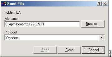
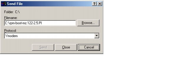
Download will be performed at 38400. Make sure your terminalemulator is set to this speed before sending file. Ready toreceive file ...Step 4
In the Filename box, browse and choose the image file to be downloaded. Also since we used the "y" option while invoking the xmodem, set the transfer protocol to ymodem or use Xmodem protocol by not specifying the -y option on the command line.
The transfer screen comes up and transfer starts. (The transfer may not start immediately; wait for some time and it should start.)
After the transfer is completed (it should typically take about 10-15 minutes), the following messages are displayed on HyperTerminal console:
Returning console speed to 9600.Please reset your terminal emulator to this speed...Step 5
Usually, due to time lag between changing HyperTerminal speed back to 9600 baud, you might see a bunch of garbage. To avoid this, disconnect and reconnect the HyperTerminal to get the console back again.
The system will reset itself from here and will boot with new software image.
Historical Information From 1.2.x Baseline
Problems Fixed in Release 1.2.11
The following is the list of problems fixed in the RPM service module firmware and software for this release. Included with each is a brief discussion of the problem. A more in-depth discussion is available in the Release Note enclosure of the problem record in Bug Navigator.
Problems Fixed in Release 1.2.00
The following is the list of problems fixed in the RPM service module firmware and software for Cisco MGX Release 1.2.00. Included with each is a brief discussion of the problem. A more in-depth discussion is available in the Release Note enclosure of the problem record in Bug Navigator.
Problems Fixed in Release 1.2.02
The following is the list of problems fixed in the service module firmware and the Release 1.2.02 software. Included with each is a brief discussion of the problem. A more in-depth discussion is available in the Release Note enclosure of the problem record in Bug Navigator.
Problems Fixed in Release 1.2.01
The following is the list of problems fixed in the service module firmware and the Release 1.2.01 software. Included with each is a brief discussion of the problem. A more in-depth discussion is available in the Release Note enclosure of the problem record in Bug Navigator.
Note
Problems Fixed in Release 1.2.00
The following is the list of problems fixed in the service module firmware and the Release 1.2.00 software. Included with each is a brief discussion of the problem. A more in-depth discussion is available in the Release Note enclosure of the problem record in Bug Navigator.
About These Release Notes (MGX 4.0.00)
Cisco documentation and additional literature are available in a CD-ROM package, which ships with your product. The Documentation CD-ROM, a member of the Cisco Connection Family, is updated monthly. Therefore, it might be more current than printed documentation. To order additional copies of the Documentation CD-ROM, contact your local sales representative or call customer service. The CD-ROM package is available as a single package or as an annual subscription.
Note that for Release 4.0.00, the user documentation (command reference, overview, and installation and configuration guides) use the MGX Release 4 and Cisco IOS documents in addition to this release note.
For RPM-PR, use the Cisco MGX Route Processor Module (RPM-PR) Installation and Configuration Guide, Release 2.1 along with this release note. The RPM-PR documentation can be found at the following MGX 8850 and MGX 8950 Release 2.1 URLs:
http://www.cisco.com/univercd/cc/td/doc/product/wanbu/8850r21/rpmpr/index.htm
http://www.cisco.com/univercd/cc/td/doc/product/wanbu/mgx8950/rel21/rpm/index.htm
If you are reading Cisco product documentation on the World Wide Web, you can submit comments electronically. Click Feedback in the toolbar, select Documentation, and click Enter the feedback form. After you complete the form, click Submit to send it to Cisco. We appreciate your comments.
New Features
RPM in MGX 8000 Release 4.0.00 supports all new and existing features introduced in the Release 2.1 baseline. There are no new features for RPM implementations using IOS Release 12.2(15)T.
Previously Released Features
RPM Image Directory Change From E:RPM to C:/FW
Until release 3.0.10, all files used by RPM were stored in E:RPM. All other service modules, including PXM, stores their firmware files in C:/FW. You can now use C:/FW (or x: from RPM-PR card) directory to download the RPM images. As with all other service modules, by storing all the firmware files, including the RPM files in C:/FW, the router blades can more easily integrate with the shelf architecture.
Note
Due to the large number and size of RPM images in the E:RPM directory, the saveallcnf command would timeout. By moving these large image files to the C:/FW directory, and leaving only the configuration files in the E:RPM directory, this change alleviates the timeouts incurred when executing the saveallcnf command.
Automatic Cell Bus Clocking
Auto Clock Setting feature is enabled using the cnfndparms command.
The CLI commands dspcbclk and cnfcbclk allow for manual setting of the cellbus clock rates, as shown in the following listing.
unknown.7.PXM.a > dspcbclk
CellBus Rate (MHz) Slots Allowable Rates (MHz)
----------------------------------------------------------
CB1 21 1, 2 21, 42
CB2 21 3, 4 21, 42
CB3 21 5, 6 21, 42
CB4 21 17 - 22 21
CB5 21 9, 10 21, 42
CB6 21 11, 12 21, 42
CB7 21 13, 14 21, 42
CB8 21 25 - 30 21
To enable automatic setting of cellbus clock rates, a node parameter must be turned on. The CLI commands dspndparms and cnfndparms manipulate the node parameters, as shown in the following listing.
unknown.7.PXM.a > dspndparmsunknown System Rev: 03.00 Oct. 02, 2002 13:42:53 PSTMGX8850 Node Alarm: MINORNODE CONFIGURATION OPTIONSOpt# Value Type Description---- ----- ---- -----------1 3600 16bit Decimal SHM Card Reset Sliding Window (secs)2 3 8bit Decimal SHM Max Card Resets Per Window (0 = infinite)3 Yes Boolean Core Redundancy Enabled4 No Boolean Expanded Memory on PXM45B Enabled5 0x0 8bit Hex Required Power Supply Module Bitmap6 0x0 8bit Hex Required Fan Tray Unit Bitmap7 0 8bit Decimal Trap Manager Aging timeout value(Hour(s))8 atm0 8bit Decimal Primary IP interface for Netmgmt9 lnPci0 8bit Decimal Secondary IP interface for Netmgmt10 No Boolean Auto Setting of Cellbus Clock Rate Enabled11 Yes Boolean Inband Node-to-Node IP Connectivity EnabledTurning node parameter 10 on allows for automatic setting of cellbus clock rates. After it is enabled, software immediately determines if any cellbus rates need to be changed. If, for example, two RPM-PR cards exist in one cellbus, that cellbus rate will be changed to 42MHz, as shown in te following listing.
unknown.7.PXM.a > cnfndparm 10 yesNODE CONFIGURATION OPTIONSOpt# Value Type Description---- ----- ---- -----------10 Yes Boolean Auto Setting of Cellbus Clock Rate EnabledOnce enabled, dspcbclk shows that mnaul setting is no longer allowed, as displayed in te following listing.
unknown.7.PXM.a > dspcbclkCellBus Rate (MHz) Slots Allowable Rates (MHz)----------------------------------------------------------CB1 21 1, 2 21, 42 (Auto Setting Enabled)CB2 21 3, 4 21, 42 (Auto Setting Enabled)CB3 21 5, 6 21, 42 (Auto Setting Enabled)CB4 21 17 - 22 21CB5 21 9, 10 21, 42 (Auto Setting Enabled)CB6 21 11, 12 21, 42 (Auto Setting Enabled)CB7 21 13, 14 21, 42 (Auto Setting Enabled)CB8 21 25 - 30 21If you attempt to manually configure cellbus clock rate while automatic cellbus rate changes are enabled, you will receive an error messafe similar to the shown in the following listing.
unknown.7.PXM.a > cnfcblclk 1 42Err: Illegal value for option -rate-cb <cellBus>, where cellBus is a string CB1..CB8-rate <clockRate>, where clockRate is 21 or 42 (MHz)unknown.7.PXM.a >New Fields Added to dspcd
The dspcd cli command on the PXM now displays the following additional front and back card information:
•
•
•
•
Prior to release 3.0.10, the following information was displayed:
rswzen2.8.PXM.a > dspcd 3rswzen2 System Rev:03.00 Aug. 26, 2002 19:25:49 PDTMGX8850 Node Alarm:MAJORSlot Number: 3 Redundant Slot:NONEFront Card Upper Card Lower Card---------- ---------- ----------Inserted Card: RPM_PR FE_RJ45 ---Reserved Card: UnReserved UnReserved UnReservedState: Active Active EmptySerial Number: ---Prim SW Rev: --- --- ---Sec SW Rev: --- --- ---Cur SW Rev: --- --- ---Boot FW Rev: --- --- ---800-level Rev: ---800-level Part#: 000-00000-00 000-00000-00 ---CLEI Code: ---Reset Reason: On Reset From ShellCard Alarm: NONEFailed Reason: NoneMiscellaneous Information:As of Release 3.0.10, the following information is displayed:
rswzen2.8.PXM.a > dspcd 1rswzen2 System Rev:03.00 Aug. 26, 2002 19:24:24 PDTMGX8850 Node Alarm:MAJORSlot Number: 1 Redundant Slot:NONEFront Card Upper Card Lower Card---------- ---------- ----------Inserted Card: RPM_PR FE_RJ45 ---Reserved Card: UnReserved UnReserved UnReservedState: Active Active EmptySerial Number: SAG06041R16 SAG053355UV ---Prim SW Rev: --- --- ---Sec SW Rev: --- --- ---Cur SW Rev: 12.2(11)T1 --- ---Boot FW Rev: 12.2(11)T1 --- ---800-level Rev: A0 B2 ---800-level Part#: 800-07424-00 800-02560-00 ---CLEI Code: BA3AY30CAA BAEIAAAAAA ---Reset Reason: On Reset From ShellCard Alarm: NONEFailed Reason: NoneMiscellaneous Information:Type <CR> to continue, Q<CR> to stop:qUsing the switchredcd Command with RPM-PR Cards to Switch from Active to Standby Card
The MGX RPM-PR uses the switchredcd command to manually change the active card to the standby card as of Cisco MGX Release 3.0 and Cisco IOS Release 12.2(8)T4) , similar to other MGX service modules. The switchredcd command replaces the softswitch command that was previously used and is now obsolete.
Be sure to execute the switchredcd command before removing an active RPM-PR card from the MGX 8000 series switch shelf.
See "Upgrade Procedures for RPM-PR Cards in MGX 8000 Release 2.1, Release 3 and Release 4 (PXM45 and PXM1E) Switches" section and "Upgrading RPM-PR Boot Software and Runtime Software for 1:N Redundancy" section.
For more information on the switchredcd command, refer to the Cisco MGX 8850, MGX 8950, and MGX 8830 Command Reference (PXM45/B and PXM1E), Release 3.
VISM-PR to RPM-PR Connectivity
The VISM-PR card supports 144 channels when used with the G.723.1 codec, whereas the current VISM card support supports 64 channels with the G.723.1 codec.
The following VISM Release 3.0 features require either the PXM1E or PXM45 card in your MGX 8000 Series switch chassis:
•
•
•
•
As of Cisco MGX Release 3.0 and Cisco IOS Release 12.2(8)T4), setting connections between a VISM-PR card and a RPM-PR card in your MGX 8000 Series switch chassis requires that you use the new VBR (NRT) 3 connection type.
If you are using a VISM-PR card in combination with either a PXM1E or PXM45 card, you must use the VBR (NRT) 3 selection when adding a connection. Use the modified addcon or cnfcon commands to configure this connection type.
For more information, refer to the Cisco VISM Installation and Configuration Guide, Release 3.
Configuring the Cell Bus Clock (CBC) Rate
As of Cisco MGX Release 3.0 and Cisco IOS Release 12.2(8)T4), when two RPM-PR cards are on the same cell bus, that is, they occupy adjacent slots (for example, slots 1 and 2, slots 3 and 4), the cell bus clock (CBC) rate will be automatically set to 42MHz. Correspondingly, if there is only one RPM on the cell bus, the clock should be at the default value of 21 MHz.
If, for any reason, one of the adjacent RPM-PRs goes to Failed or Empty state, the CBC for that cell bus must be reconfigured for the Traffic Shaping to work correctly on the active RPM. On MGX Release 3, reconfiguration of CBC rate from 42MHz to 21 MHz is done automatically.
RPM makes use of idle cells for Traffic Shaping and Scheduling. If there are two RPMs in adjacent slots on the same cell bus and one of the RPMs is put into a Failed state by the PXM, while that card is actually alive, then the "Failed" RPM must stop sending idle cells to avoid impacting the Traffic Shaping on the adjacent functional RPM. The command that implements the RPM support for this feature is rpm-auto-cbclk-change
rpm-auto-cbclk-change will enable the RPM to stop sending idle cells in the event of being put into a "FAILED" state by the PXM and thus prevent an impact on the Traffic Shaping on an adjacent functional RPM.
no rpm-auto-cbclk-change will disable the feature to stop sending of idle cells if the RPM is put into a FAILED state. This command may be used if Traffic Shaping is not required.
The following screen output displays an example of the rpm-auto-cbclk-change command.
RPM-11#config terminalEnter configuration commands, one per line. End with CNTL/Z.RPM-11(config)#int sw1RPM-11(config-if)#rpm-auto-cbclk-changeRPM-11(config-if)#endRPM-11#write memBuilding configuration...[OK]RPM-11#show run int sw1Building configuration...Current configuration :142 bytes!interface Switch1no ip addressno atm ilmi-keepaliverpm-auto-cbclk-changeswitch autoSynch offend! rpm_tag_id Apr 04 2002 02:49:04If Traffic Shaping is not a requirement, enter the no rpm-cbclk-change command, either manually or during card configuration. The following screen output displays an example of the no rpm-auto-cbclk-change command.
RPM-11#config terminalEnter configuration commands, one per line. End with CNTL/Z.RPM-11(config)#int sw1RPM-11(config-if)#no rpm-auto-cbclk-changeRPM-11(config-if)#endRPM-11#write memBuilding configuration...[OK]RPM-11#show run int sw1Building configuration...Current configuration :145 bytes!interface Switch1no ip addressno atm ilmi-keepaliveno rpm-auto-cbclk-changeswitch autoSynch offend! rpm_tag_id Apr 04 2002 02:49:57
Note
LDP on RPM-PR in MGX 8850 and MGX 8950
The MPLS label distribution protocol (LDP), as standardized by the Internet Engineering Task Force (IETF) and as enabled by Cisco IOS software, allows the construction of highly scalable and flexible IP Virtual Private Networks (VPNs) that support multiple levels of services.
LDP provides a standard methodology for hop-by-hop, or dynamic label, distribution in an MPLS network by assigning labels to routes that have been chosen by the underlying Interior Gateway Protocol (IGP) routing protocols. The resulting labeled paths, called label switch paths or LSPs, forward label traffic across an MPLS backbone to particular destinations. These capabilities enable service providers to implement Cisco's MPLS-based IP VPNs and IP+ATM services across multivendor MPLS networks.
From an historical and functional standpoint, LDP is a superset of Cisco's pre-standard Tag Distribution Protocol (TDP), which also supports MPLS forwarding along normally routed paths. For those features that LDP and TDP share in common, the pattern of protocol exchanges between network routing platforms is identical. The differences between LDP and TDP for those features supported by both protocols are largely embedded in their respective implementation details, such as the encoding of protocol messages, for example.
This software release of LDP provides the means for transitioning an existing network from a TDP operating environment to an LDP operating environment. Thus, you can run LDP and TDP simultaneously on any given router platform. The routing protocol that you select can be configured on a per-interface basis for directly connected neighbors and on a per-session basis for non directly connected (targeted) neighbors. In addition, a label switch path (LSP) across an MPLS network can be supported by LDP on some hops and by TDP on other hops.
MPLS LDP offers the following features:
•
•
•
Multi-LVC on RPM in MGX 8850 and MGX 8950 Release 2.1.76 Running Cisco IOS Release 12.2(8)T1
This feature enables support for initiation of Multiple label switched paths (LSPs) per destination on the RPM. Different label switched paths are established for different class of services. This feature enables interface level queueing rather than per-vc level on the RPM based on MPLS class of service policy. With Multi-LVC support, customers can deploy IP VPN services with Class of service SLAs.
Multiprotocol Label Switching (MPLS) over ATM using VC Merge in MGX 8850 and MGX 8950 Release 2.1.76 Running Cisco IOS Release 12.2(8)T
The virtual circuit (VC) merge facility allows a switch to aggregate multiple incoming flows with the same destination address into a single outgoing flow. Wherever VC merge occurs, several incoming labels are mapped to one single outgoing label. Cells from different virtual channel identifiers (VCIs) going to the same destination are transmitted to the same outgoing VC using multipoint-to-point connections. This sharing of labels reduces the total number of VCs required for label switching.
Without VC merge, each path consumes one label VC on each interface along the path. VC merge reduces the label space shortage by sharing labels for different flows with the same destination. Therefore, VC-Merge connections are unidirectional, and furthermore, all merged connections must be of the same service type.
Note
VC Merge is enabled by default when the MPLS over ATM network is configured and is only used when the RPM is used as an LSC (Label Switch Controller). Because it is enabled by default, the only commands necessary are:
no tag-switching atm vc-merge to disable VC Merge
and
tag-switching atm vc-merge to enable VC Merge
For more information, see MPLS Label Switch Controller and Enhancements at the following URL:
http://www.cisco.com/univercd/cc/td/doc/product/software/ios122/122newft/122t/122t8/ftlsc.htm#xtocid15
Bypass Feature for RPM in Cisco IOS Release 12.2(4)T
Note
RPM cards have a maximum storage of 128 KB for the NVRAM. This size limitation creates a problem for customers with large configurations, who find it impossible to store the complete configuration in the NVRAM, even with compression enabled.
In order to support storage of large configuration files, a new bypass feature is now available in the 12.2(4)T IOS Release. With the bypass feature enabled, the enhanced write memory command is used to bypass the NVRAM and save the configuration on the file auto_config_slot## located in E:/RPM, where ## represents the zero-padded slot number in which the RPM-PR card is seated in the MGX chassis.
To enable the bypass feature, issue the command rpmnvbypass from the IOS run time image—not in the IOS boot image.
To disable the bypass feature, issue the command no rpmnvbypass.
To verify that the bypass feature is either enabled or disabled, issue the show running-configuration command. If the bypass feature is enabled, rpmnvbypass is seen on the display. If it is not seen, the feature is not enabled.
Note
Table 6 contains cautions important to the successful usage of the bypass feature.
Example 6 through Example 10 illustrate how the bypass feature is enabled and disabled, and how to validate each of these actions from the configuration display.
Example 6 Running configuration without the bypass feature enabled
rpm_slot02#show running-configBuilding configuration...Current configuration : 470 bytes!version 12.2service timestamps debug uptimeservice timestamps log uptimeno service password-encryption!hostname rpm_slot02!boot system c:rpm-js-mz.<new_rel>enable password cisco!ip subnet-zero!!!!interface Switch1no ip addressno atm ilmi-keepaliveswitch autoSynch off!ip classlessno ip http serverip pim bidir-enable!!snmp-server community public ROsnmp-server community private RW!!line con 0line aux 0line vty 0 4no login!endExample 7 Enable the bypass feature (rpmnvbypass)
rpm_slot02#rpm_slot02#configure terminalEnter configuration commands, one per line. End with CNTL/Z.rpm_slot02(config)#rpmnvbypassThe "boot config" statement has been (re)added to yourrunning configuration. Do not remove it else risk notusing the nvbypass featurerpm_slot02(config)#endrpm_slot02#Example 8 Running configuration with bypass feature enabled (note rpmnvbypass at end of output)
rpm_slot02#show running-configBuilding configuration...Current configuration : 515 bytes!version 12.2service timestamps debug uptimeservice timestamps log uptimeno service password-encryption!hostname rpm_slot02!boot system c:rpm-js-mz.<new_rel>boot config c:auto_config_slot02 <==== Line added as per output aboveenable password cisco!ip subnet-zero!!!!interface Switch1no ip addressno atm ilmi-keepaliveswitch autoSynch off!ip classlessno ip http serverip pim bidir-enable!!snmp-server community public ROsnmp-server community private RW!!line con 0line aux 0line vty 0 4no login!rpmnvbypassendExample 9 Disable the bypass feature (no rpmnvbypass)
rpm_slot02#configure terminalEnter configuration commands, one per line. End with CNTL/Z.rpm_slot02(config)#no rpmnvbypassrpm_slot02(config)#endrpm_slot02#Example 10 Running configuration after the bypass feature is disabled
rpm_slot02#show running-configBuilding configuration...Current configuration : 503 bytes!version 12.2service timestamps debug uptimeservice timestamps log uptimeno service password-encryption!hostname rpm_slot02!boot system c:rpm-js-mz.<new_rel>boot config c:auto_config_slot02enable password cisco!ip subnet-zero!!!!interface Switch1no ip addressno atm ilmi-keepaliveswitch autoSynch off!ip classlessno ip http serverip pim bidir-enable!!snmp-server community public ROsnmp-server community private RW!!line con 0line aux 0line vty 0 4no login!endrpm_slot02#Features Not Supported in This Release
•
•
RPM Redundancy Support
RPM 1:N redundancy is used to switch configuration and traffic from one RPM card to another. The main benefits are:
•
•
•
SNMP MIB
SNMP MGX Release 3.0 MIB are provided with the delivery of this release. The MIB is in standard ASN.1 format and is located in the same directory within the release bundle on CCO. These files may be compiled with most standards-based MIB compilers. The tar file for MIB contains the file release notes that contains the MIB release notes.
For changes in this MIB from the previous release, please refer to the MIB release notes.
Note
Notes and Cautions
The following notes and cautions should be reviewed before using this release.
UPC Connection Parameters
In Release 2.1.60 and higher, the default PCR is 50 cps, and the default for policing is enabled. These settings are insufficient for running RPM ISIS protocol over the connection, and with such settings, the ISIS protocol will fail. The PCR value needs to be increased, depending upon the number of interfaces configured for ISIS on the RPM.
Depending upon your connection type, you can use the following CLIs to modify the PCR parameter.
•
•
•
•
Booting the RPM-PR
Refer to Chapter 5, "Configuring the MGX RPM-PR" in the Cisco MGX Route Processor Module RPM-PR) Installation and Configuration Guide, Release 3 for complete details on configuring the RPM-PR cards. A summary of the booting and upgrading procedures is presented here for your convenience.
When the RPM-PR is booted, the boot image must be the first file in the bootflash. If the bootflash does not have a valid boot image as a first file, the card may not be able to boot and can result in bootflash corruption. If the bootflash is corrupted, you will have to send the card back for an external burn with a valid boot image.
You can reboot the RPM-PR from the PXM by entering the command resetcd <card_number> from the switch CLI, where card_number is the slot number of the RPM-PR that is being rebooted.
Note
Also, you can reboot the RPM-PR from the RPM-PR using the RPM-PR console port and entering the reload command.
Each time you turn on power to the RPM-PR, by inserting the RPM-PR into the MGX 8850 or MGX 8950, it goes through the following boot sequence:
1.
2.
The source of the Cisco IOS image is determined by the configuration register setting. To verify this setting, you can enter either the show version or show bootvar command. (Refer to the "Viewing the Hardware Configuration" section of the Cisco MGX Route Processor Module Installation and Configuration Guide, Release 2.1.
a.
b.
3.
a.
b.
4.
5.
If you want to load from a specific configuration file, you should enter either the boot config bootflash:<config_file> command or the boot config e:<config_file> command.
6.
The first time you boot the RPM-PR, configure the RPM-PR interfaces and save the configuration to a file in NVRAM. Then follow the procedure described in "Initializing the RPM-PR Card." For information on the Cisco IOS instructions, refer to Appendix C, "IOS and Configuration Basics"of the Cisco MGX Route Processor Module Installation and Configuration Guide, Release 2.1.
RPM-PR Bootflash Precautions
The RPM-PR bootflash is used to store boot image, configuration and run time files. The Flash stores and accesses data sequentially, and the RPM-PR boot image must be the first file stored to successfully boot the card. Erasing the boot image or moving it from the first position on the Flash will cause the card to not boot.
The RPM boot image, which comes loaded on the Flash, will work for all RPM IOS images. Therefore, there is no reason to ever delete or move the factory installed boot image.
Caution
In order to avoid this unnecessary failure, requiring card servicing, you should
•
•
•
As long as the boot file remains intact in the first position on the flash, the RPM will successfully boot.
CLI Modifications in MGX Release 4.0.00
There are no new or modified RPM-PR CLI commands in Release 4.0.00.
Limitations and Restrictions
CWM Recognition of RPM-PR Back Card
CWM does not distinguish between the Ethernet back card versions installed with the RPM-PR. There is no functionality difference.
RPM Front Card Resets on the Back Card Removal
The RPM front card may reset on an MGX 8850 or MGX 8950 switch when the ethernet back card is removed or inserted.
This reset problem can be easily avoided if shut interface is executed before the removal of the back card.
RPM-PR Back Ethernet Card Support
For Ethernet connectivity with the RPM-PR, the model "/B" four-port Ethernet back card is required (order number: MGX-RJ45-4E/B).
RPM-PR Limitations and Restrictions (PXM45 and PXM1E)
The RPM-PR and MPLS limitations and restrictions that apply to this release are as follows:
•
•
•
•
•
•
•
•
•
•
•
•
•
•
•
–
–
•
•
Problems Fixed in This Release
The following is the list of problems fixed in the RPM service module firmware and software for this release. Included with each is a brief discussion of the problem. A more in-depth discussion is available in the Release Note enclosure of the problem record in Bug Navigator.
Open Caveats in Release 12.2.15T
Table 2 lists the open caveats in Cisco IOS Release 12.2.15T.
Table 8 Open Caveats in Cisco IOS Release 12.2.15T
CSCec16481
Symptom:
A Cisco device running Internetwork Operating System (IOS) and enabled for the Open Shortest Path First (OSPF) Protocol is vulnerable to a Denial of Service (DoS) attack from a malformed OSPF packet. The OSPF protocol is not enabled by default.
Conditions:
The vulnerability is only present in IOS release trains based on 12.0S, 12.2, and 12.3. Releases based on 12.0, 12.1 mainlines and all IOS images prior to 12.0 are not affected. Refer to the Security Advisory for a complete list of affected release trains.
Workaround:
Further details and the workarounds to mitigate the effects are explained in the Security Advisory which is available at the following URL:
http://www.cisco.com/warp/public/707/cisco-sa-20040818-ospf.shtml.
CSCdz79827
Symptom:
While performing MIB walk on the whole CISCO-IP-STAT-MIB MIB, cipPrecedenceEntry goes through a loop.
Conditions:
While performing MIB walk on CISCO-IP-STAT-MIB MIB, cipPrecedenceEntry loops around and does not exit out of the mib walk.
Workaround: None
CSCdz87255
Symptom:
RPM-XF resets if an incorrect name is specified in the "mic rel pxf " command
Conditions:
In the "microcode reload pxf" command, the file name specified is not present in the "C:FW" directory on the PXM.
Workaround:
Make sure the correct filename is specified.
CSCea59731
Symptom:
When querying on the ifName , the output does not follow the desired format.As a result , SNMP dependent tools will fail due to unexpected result.
Conditions:
This symptom is observed while issuing snmpwalk on the node for ifName.
Workaround: None
CSCea77841
Symptom:
Trace back error: "rpm_red_copy_file_to_dev: copy failed" observed after RPM-PR card reload.
Conditions:
Not enough free space left on the bootflash.
Workaround: None
CSCdx04380
Symptom:
Status field of an RPM interface shows unknown(3).Database schema says it can be onle 1 or 2
Workaround: None
CSCdz56476
Symptom:
Traceback errors - "%SYS-2-BADSHARE: Bad refcount in retparticle" were observed on RPM-PR (Route Processor Module)
Conditions:
After clearing the arp table and reseting the IXIA FE ports, traceback error messages appeared on the console.
Workaround: None
CSCea22766
Symptom:
PXM1 Controller card got reset due to starved tChStats task.
Conditions:
While connection proxy and show command scripts were running in the back ground and lots of BGP routes were also being updated, during this setup, PXM1 controller card got reset. PXM1 logs suggested tChStats task was starved, which caused tRootTask to reset PXM1.
Workaround: None
CSCea26869
Symptom:
IPC Low Buffer traceback observed on PE.
Conditions:
After running the multiple show commands and injecting & withdrawing VRF routes from CE, PE kept getting IPC low buff trace back messages.
Workaround: None
CSCdz32991
Symptom:
RPM-PR on the MGX8850 with PXM45 as controller card, occasionally drops ping packets due to CRC error.
Conditions:
RPM-PR on the MGX8850 with PXM45 as controller card, occasionally drops ping packets due to CRC error. The ping packets came from the 7200 router on BPX.
Workaround:
None
CSCdz33457
Symptom:
RPM-PR card reloaded after reporting Traceback messages on console; also generated crashinfo file.
Condition:
This happened after "ip rtp compression-connection 300" command was issued on the RPM-PR card, which resulted in reload/reset of the said card.
Workaround:
None
CSCdz48135:
Symptom:
On an RPM-PR running IOS 12.2(8)T4 / 12.2(13)T, service policy command can be configured under the PVC on a switch1 interface.
Conditions:
Service policy command can be configured under the PVC on a subinterface for the Switch1 interface on RPM-PR installed in MGX8230 / MGX8850 node (w/ PXM45 and/or PXM1E controller card). Although the service policy command is accepted, the queueing strategy remains FIFO.
Workaround:
None
Compatibility Notes
RPM Boot File and Firmware File Names and Sizes
The following table displays the RPM boot and firmware file names and sizes for this release.
Table 9 RPM Boot and Firmware File Names and Sizes
rpm-boot-mz.122-15.T
2796756
rpm-js-mz.122-15.T
9120208
RPM Compatibility Matrix
IOS Version
12.1(5.3)T_XT
12.2(2)T2
12.2(4)T
CWM
10.4.01
10.4.01 Patch 1
10.5
IOS Version
12.2(4)T1
12.2(8)T11
12.2(8)T4
12.2(11)T1
12.2(11)T2
12.2(15)T
CWM
10.5.10
10.5.10 Patch 1
11.0.00
11.0.10
11.0.10 Patch 1
12.0.00
1 MGX 1.2.02 has also been certified with IOS 12.2(4)T3.
MGX RPM-PR Hardware
Table 10 shows the front card and back card compatibility for RPM-PR hardware supported in this release. The table lists the card model/ name, part numbers, the minimum version and the minimum revisions of each card supported. Note that there may be more than one 800 level part numbers for the same front cards. The minimum version is identified by the last 2 digits of the 800 level numbers.
Special Installation and Upgrade Requirements
Existing customers should use the upgrade procedures Upgrade Procedures for RPM-PR Cards in MGX 8000 Release 2.1, Release 3 and Release 4 (PXM45 and PXM1E) Switches, Historical Information From 3.x Baseline, and Historical Information From 2.1.7x Baseline to upgrade. A graceful upgrade from any release previous to the current release is supported. For new customers, the image will be pre-installed and should use the PXM installation procedure to upgrade to future maintenance releases.
Cisco IOS Release Compatibility Information
This section describes the installation requirements and guidelines for RPM modules installed with this release.
All IOS firmware can be downloaded from CCO from the following location:
http://www.cisco.com/kobayashi/sw-center/sw-ios.shtml
About the Cisco IOS 12.2(15)T Release
The Cisco IOS 12.2(15)T supports existing features on the MGX-RPM-PR and MGX-RPM-128M/B cards.
About the Cisco IOS 12.2(11)T1 Release
The Cisco IOS 12.2(11)T1 supports existing features on the MGX-RPM-PR card.
About the Cisco IOS 12.2(8)T4 Release
The Cisco IOS 12.2(8)T4 supports existing features on the MGX-RPM-PR card.
About the Cisco IOS 12.2(8)T1 Release
The Cisco IOS 12.2(8)T1 supports existing features on the MGX-RPM-PR card and the CBC clock rate configuration feature described in "Features Not Supported in This Release" section.
About the Cisco IOS 12.2(4)T3 Release
The Cisco IOS 12.2(4)T3 supports existing features on the MGX-RPM-PR card.
About the Cisco IOS 12.2(4)T1 Release
The Cisco IOS 12.2(4)T1 or higher is used with MGX Release 21.70. This IOS release supports new RPM features and continues to support existing features on the RPM-PR card.
Note that MPLS inter-AS and MPLS TE are not supported features on RPM for this release.
About the Cisco IOS 12.2(4)T Release
The Cisco IOS 12.2(4)T or higher is used with MGX Release 2.1.60. This IOS release supports new RPM features and continues to support existing features on the RPM-PR card.
Note that MPLS inter-AS and MPLS TE are not supported features on RPM for this release.
Upgrade Procedures for RPM-PR Cards in MGX 8000 Release 2.1, Release 3 and Release 4 (PXM45 and PXM1E) Switches
The following sections describe how to upgrade boot and runtime software on RPM-PR cards in detail.
Upgrading RPM Boot Software
At the factory, a boot file is installed in the bootflash on the RPM-PR card and is used to boot the card. The runtime software is updated more frequently than the boot software. However, the boot software is updated occasionally. When you are updating runtime software, check Table 9 to see if a boot software upgrade is required.
The boot software is stored in bootflash memory on the RPM card. To manage the software in bootflash, you access it as if it were a hard disk. For example, in copy and delete file commands, files are identified as bootflash:filename (which is similar to e:filename).
The following example shows a directory of bootflash contents:
Router(boot)#show flash:-#- ED --type-- --crc--- -seek-- nlen -length- -----date/time------ name1 .D config D4F7352A 40330 18 686 Jan 30 2001 18:18:41 auto_config_slot092 .D config CBF007C1 40660 9 688 Feb 22 2001 15:33:11 slot9.cnf3 .. image F596869A 2973E8 27 2452744 Feb 28 2001 03:16:05 rpm-boot-mz_002.001.070.202
Note
In the example above, the numbers in the left column indicate the order in which the RPM-PR card will try to load software. The second column shows that the first two files are marked for deletion (D). The last column lists the names of the files stored in bootflash.
When managing the bootflash, you need to keep in mind the following:
•
•
Caution
Upgrading RPM Runtime Software
The runtime software on the RPM can be loaded from the following sources:
•
•
•
Cisco Systems recommends that you configure the RPM card to load from the E:RPM directory on the PXM45 hard disk. Note that images will load much faster from bootflash, but if you are using multiple RPM cards, it takes longer to complete an upgrade because the runtime software must be copied to each RPM card's bootflash instead of to a single location.
At startup, the RPM card attempts to load the software in the order listed in the startup-config file. The following example shows an excerpt from a startup-config file:
!boot system e:rpm-js-mz.122-4.Tboot system bootflash:rpm-js-mz.122-4.Tboot config c:auto_config_slot09logging rate-limit console 10 except errorsenable password cisco!In the startup-config file example, the RPM card attempts to load the runtime software from the PXM45 card (E:rpm-js-mz.122-4.T) first, and if that fails, it attempts to load the image copy stored in bootflash. This configuration takes longer to upgrade, but it assures the card can reboot if someone accidentally removes the file on the PXM45 hard disk.
Note
To configure the RPM to load upgraded runtime software from the PXM45 hard disk, you need to do the following:
•
•
•
RPM-PR cards can be configured for 1:N redundancy as well as for non-redundant configurations. The procedures for both types of configuration are in the sections that follow.
Tip
Upgrade Procedure for Boot Software and Runtime Software for Non-Redundant Cards
The following procedure describes how to upgrade boot software and runtime software.
Note
Step 1
Step 2
Step 3
pop20two.7.PXM.a > cc 9(session redirected)Router>The switch displays the IOS prompt for the router on the RPM-PR card. From this point on, all commands are Cisco IOS commands.
Note
Step 4
Router>enablePassword:Router#Step 5
Router#dir e:Directory of c:/65539 -rw- 815 Sep 13 2001 23:51:10 auto_config_slot0965540 -rw- 2588780 Mar 22 2001 19:06:54 rpm-boot-mz_002.001.070.20184611 -rw- 2452768 Apr 05 2001 05:34:44 rpm-boot-mz.122-4.T66805 -rw- 8529104 Mar 22 2001 19:09:00 rpm-js-mz_002.001.070.20185809 -rw- 7936012 Apr 05 2001 06:28:54 rpm-js-mz.122-4.T104857600 bytes total (83068928 bytes free)Step 6
Router#show flash:-#- ED --type-- --crc--- -seek-- nlen -length- -----date/time------ name1 .. image F596869A 296D88 27 2452744 Feb 28 2001 03:16:05 rpm-boot-mz_002.001.070.20130315128 bytes available (2452872 bytes used)Step 7
Router#copy c:rpm-boot-mz.122-4T bootflash:Destination filename [rpm-boot-mz.122-4T]?CCCCCCCCCCCCCCCCCCCCCCCCCCCCCCCCCCCCCCCCCCCCCCCCCCCCCCCCCCCCCCCCCCCCCCCCCCCCCCCCCCCCCCCCCC CCCCCCCCCCCCCCCCCCCC2334044 bytes copied in 35.768 secs (66686 bytes/sec)
Tip
Step 8
Step 9
Router#del bootflash:Delete filename []? rpm-js-mzDelete bootflash:rpm-js-mz? [confirm]Router#
Tip
Step 10
Router(boot)#squeeze flash:All deleted files will be removed. Continue? [confirm]ySqueeze operation may take a while. Continue? [confirm]Squeeze of bootflash completeStep 11
Caution
Tip
Tip
Once in rommon mode, you can enter the dir bootflash: command to display the images in bootflash. To boot one of the images, enter a boot command the following format: boot bootflash:filename.
See Using XModem to Download Flash to RPM Cards.
Note
Step 12
Step 13
Step 14
8850_LA.8.PXM.a > copy rpm-js-mz.122-4.T rpm-js-mzStep 15
Step 16
pop20two.7.PXM.a > cc 9(session redirected)Router>The switch displays the IOS prompt for the router on the RPM-PR card. From this point on, all commands are Cisco IOS commands.
Note
Step 17
Router>enablePassword:Router#Step 18
Router# boot config e:auto_config_slot#Step 19
Router#show bootvarBOOT variable = e:rpm-js-mz.122-4.T,12;CONFIG_FILE variable = c:auto_config_slot09BOOTLDR variable does not existConfiguration register is 0x2In the example above, the startup runtime software file is E:rpm-js-mz.122-4.T, and it has a version number attached to it. Another way to view the boot list is to enter the show startup-config command and look for the boot system commands.
Step 20
Router#config terminalEnter configuration commands, one per line. End with CNTL/Z.Step 21
Router(config)# no boot systemStep 22
Router(config)# boot system e:filenameReplace the filename variable with the name of the new runtime file that was previously transferred to the E:RPM directory on the switch. For example:
Router(config)# boot system e:rpm-js-mzIf you want to enter additional boot system commands, enter them in the order in which you want the RPM card to use them. The following example adds a statement to load from bootflash if the runtime file is not found on the PXM45 hard disk:
Router(config)# boot system bootflash:rpm-js-mz.122-4.T
Note
Step 23
Router(config)#^ZRouter#copy run startDestination filename [startup-config]?Building configuration...[OK]Step 24
Step 25
Router#cc 8(session redirected)8850_LA.8.PXM.a > resetcd 9The card in slot number 9, will be reset. Please confirm actionresetcd: Do you want to proceed (Yes/No)? y
Upgrading RPM-PR Boot Software and Runtime Software for 1:N Redundancy
Redundancy must be established before you use the procedure in this section. If redundancy has not been established, upgrade each RPM-PR card using the procedure in the next section, "Upgrading Without Redundancy".
To upgrade the RPM-PR runtime software for 1:N redundancy, use the following procedure. (Note that the directory on the PXM45 card uses (E:) and the directory within the router card uses (e:).)
The following procedure describes how to upgrade boot software and runtime software.
Note
Step 1
Step 2
Step 3
pop20two.7.PXM.a > cc 9(session redirected)Router>The switch displays the IOS prompt for the router on the RPM-PR card. From this point on, all commands are Cisco IOS commands.
Note
Step 4
Router>enablePassword:Router#Step 5
Router#dir e:Directory of c:/65539 -rw- 815 Sep 13 2001 23:51:10 auto_config_slot0965540 -rw- 2588780 Mar 22 2001 19:06:54 rpm-boot-mz_002.001.070.20184611 -rw- 2452768 Apr 05 2001 05:34:44 rpm-boot-mz.122-4.T66805 -rw- 8529104 Mar 22 2001 19:09:00 rpm-js-mz_002.001.070.20185809 -rw- 7936012 Apr 05 2001 06:28:54 rpm-js-mz.122-4.T104857600 bytes total (83068928 bytes free)Step 6
Router#show flash:-#- ED --type-- --crc--- -seek-- nlen -length- -----date/time------ name1 .. image F596869A 296D88 27 2452744 Feb 28 2001 03:16:05 rpm-boot-mz_002.001.070.20130315128 bytes available (2452872 bytes used)Step 7
Router#copy c:rpm-boot-mz.122-4.T bootflash:Destination filename [rpm-boot-mz.122-4.T]?CCCCCCCCCCCCCCCCCCCCCCCCCCCCCCCCCCCCCCCCCCCCCCCCCCCCCCCCCCCCCCCCCCCCCCCCCCCCCCCCCCCCCCCCCC CCCCCCCCCCCCCCCCCCCC2334044 bytes copied in 35.768 secs (66686 bytes/sec)
Tip
Step 8
Step 9
Router#del bootflash:Delete filename []? rpm-js-mzDelete bootflash:rpm-js-mz? [confirm]Router#
Tip
Step 10
Router(boot)#squeeze flash:All deleted files will be removed. Continue? [confirm]ySqueeze operation may take a while. Continue? [confirm]Squeeze of bootflash completeStep 11
Caution
Tip
Tip
Once in rommon mode, you can enter the dir bootflash: command to display the images in bootflash. To boot one of the images, enter a boot command the following format: boot bootflash:filename.
See Using XModem to Download Flash to RPM Cards.This ends the boot software upgrade procedure for the primary card. The following steps are for upgrading the runtime software. If you do not want to upgrade the runtime software for the primary card, skip steps 12 through 24 and go to step 25 to upgrade the boot software on the secondary card.
Step 12
Step 13
8850_LA.8.PXM.a > copy rpm-js-mz.122-4.T rpm-js-mzStep 14
Step 15
Step 16
pop20two.7.PXM.a > cc 9(session redirected)Router>The switch displays the IOS prompt for the router on the RPM-PR card. From this point on, all commands are Cisco IOS commands.
Note
Step 17
Router>enablePassword:Router#Step 18
Router# boot config e:auto_config_slot#Step 19
Router#show bootvarBOOT variable = e:rpm-js-mz,12;CONFIG_FILE variable = c:auto_config_slot09BOOTLDR variable does not existConfiguration register is 0x2In the example above, the startup runtime software file is e:rpm-js-mz.122-4.T, and it has a version number attached to it. Another way to view the boot list is to enter the show startup-config command and look for the boot system commands.
Step 20
Router#config terminalEnter configuration commands, one per line. End with CNTL/Z.Step 21
Router(config)# no boot systemStep 22
Router(config)# boot system e:filenameReplace the filename variable with the name of the new runtime file that was previously transferred to the E:RPM directory on the switch. For example:
Router(config)# boot system e:rpm-js-mzIf you want to enter additional boot system commands, enter them in the order in which you want the RPM card to use them. The following example adds a statement to load from bootflash if the runtime file is not found on the PXM45 hard disk:
Router(config)# boot system bootflash:rpm-js-mz.122-4.T
Note
Step 23
Router(config)#^ZRouter#copy run startDestination filename [startup-config]?Building configuration...[OK]Step 24
Step 25
Router#cc 8(session redirected)Step 26
8850_LA.8.PXM.a > switchredcd <fromSlot> <toSlot>Replace <fromSlot> with the slot number of the primary card. Replace <toSlot> with the slot number of the secondary card.
This step makes the secondary card active and resets the primary RPM-PR card. When the Primary card resets, it loads the upgraded software.
Step 27
Step 28
This ends the boot software upgrade on the secondary card. If you do not want to upgrade the runtime software, go to step 30.
The following steps are for upgrading runtime software on the secondary card.
Step 29
Step 30
8850_LA.8.PXM.a > switchredcd <fromSlot> <toSlot>Replace <fromSlot> with the slot number of the secondary card. Replace <toSlot> with the slot number of the primary card.
This step makes the primary card active and resets the secondary RPM-PR card. When the reset is complete, the secondary card is ready to run the upgraded software.
Step 31
Step 32
Using XModem to Download Flash to RPM Cards
Use the xmodem feature to download the flash to an RPM/B or RPM-PR card. During this process, the card should be connected to a target machine through HyperTerminal with settings of 9600, n, 8, and 1.
Step 1
rommon 1> privYou now have access to the full set of monitor commands. Warning: some commands will allow you to destroy your configuration and/or system images and could render the machine unbootable.Step 2
rommon 2 > xmodemusage: xmodem [-cys]-c CRC-16-y ymodem-batch protocol-s<speed> Set speed of download, where speed may be1200|2400|4800|9600|19200|38400rommon 3 >The command line options for xmodem are as follows:
Note
Note
For example:
rommon 4> xmodem -cys 38400Do not start sending the image yet...Invoke this application for disaster recovery. Do you wish tocontinue? y/n [n]: yNote, if the console port is attached to a modem, both theconsole port and the modem must be operating at the same baudrate. Use console speed 38400 bps for download [confirm]Step 3
Note
The console will display the following message:
Download will be performed at 38400. Make sure your terminalemulator is set to this speed before sending file. Ready toreceive file ...Step 4
In the Filename box, browse and choose the image file to be downloaded. Also since we used the "y" option while invoking the xmodem, set the transfer protocol to ymodem or use Xmodem protocol by not specifying the -y option on the command line.
The transfer screen comes up and transfer starts. (The transfer may not start immediately; wait for some time and it should start.)
After the transfer is completed (it should typically take about 10-15 minutes), the following messages are displayed on HyperTerminal console:
Returning console speed to 9600.Please reset your terminal emulator to this speed...Step 5
Usually, due to time lag between changing HyperTerminal speed back to 9600, you might see a bunch of garbage. To avoid this, disconnect and reconnect the HyperTerminal to get the console back again.
The system will reset itself from here and will boot with new software image.
Historical Information From 3.x Baseline
Problems Fixed in 3.0.10
The following is the list of problems fixed in the RPM-PR service module firmware and software for this release. Included with each is a brief discussion of the problem. A more in-depth discussion is available in the Release Note enclosure of the problem record in Bug Navigator.
Problems Fixed in Release 3.0.00
The following is the list of problems fixed in the RPM-PR service module firmware and software for MGX Release 3.0.00. Included with each is a brief discussion of the problem. A more in-depth discussion is available in the Release Note enclosure of the problem record in Bug Navigator.
Historical Information From 2.1.7x Baseline
Anomalies Resolved in Release 2.1.79
CSCdx31305; S1; Secondary RPM IPC seat gets deleted when it NAKs the GO-ACTIVE req
CSCdx38360; S1; RPM-PR went into failed/discovering state after multiple swithcc
CSCdx44536; S1; switchredcd for RPMs shouldnt be allowed for cards in discovering
CSCdv76791; S3; dspcd command output does not display card information for RPM
CSCdw43588; S3; After switchover,RPM_PR red card data not exist in config file
Anomaly Status Changes in 2.1.79
Table 13 Anomalies that have changed status in Release 2.1.79
CSCdu49855
JUP: Temporary IPC-error -- pxm45-RPM_PR related. Unreproducible
Anomaly Status Changes in Release 2.1.76
Table 14 lists anomalies that have changed status in Release 2.1.76.
Table 14 Anomalies that have changed status in Release 2.1.76
CSCdw71214
Switchredcd cmd is not completely disallowed from RPM 1:N mode. Duplicate of CSCdt95815
Anomalies Resolved in Release 2.1.75
Table 15 lists the anomalies resolved in release 2.1.75.
Anomaly Status Changes in Release 2.1.75
Table 16 lists anomalies that have changed status in Release 2.1.75.
Anomalies Resolved in Release 2.1.70
Table 17 lists the anomalies that have been resolved in Release 2.1.70.
Anomaly Status Changes in Release 2.1.70
Table 18 lists anomalies that have changed status in Release 2.1.70.
Related Documentation
This "Related Documentation" section describes the technical manuals and release notes listed in the "Guide to Cisco Multiservice Switch Documentation." That guide, part DOC-7815358=, shipped with your product.
The following Cisco publications contain information related to the operation of this product and associated equipment in a Cisco WAN switching network.
Note
There are several ways you can find these documents online:
•
•
•
Cisco WAN Manager Release 12
Table 19 lists the product documentation for the Cisco WAN Manager (CWM) network management system for Release 12.
Cisco MGX 8850 (PXM45) Multiservice Switch Release 4
Table 20 lists the product documentation for the installation and operation of the Cisco MGX 8850 (PXM45) Multiservice Switch Release 4.
Cisco MGX 8850 (PXM1E) Multiservice Switch Release 4
Table 21 lists the product documentation for the installation and operation of the Cisco MGX 8850 (PXM1E) Multiservice Switch Release 4.
Cisco MGX 8950 Multiservice Service Release 4
Table 22 lists the product documentation for the installation and operation of the Cisco MGX 8950 Multiservice Switch Release 4.
SES PNNI Release 4
Table 23 lists the product documentation for the understanding, the installation, and the operation of the Service Expansion Shelf (SES) Private Network-to-Network Interface (PNNI) Controller.
Cisco MGX 8830 Multiservice Switch Release 4
Table 24 lists the product documentation for the installation and operation of the Cisco MGX 8830 Multiservice Switch Release 4.
Cisco WAN Switching Software Release 9.4
Table 25 lists the product documentation for the installation and operation of the Cisco WAN Switching Software Release 9.4.
MGX 8850 (PXM1) Edge Concentrator Release 1.2.20
Note
Table 26 lists the product documentation for the installation and operation of the Cisco MGX 8850 Edge Concentrator.
MGX 8250 Edge Concentrator Release 1.2.20
Table 27 lists the product documentation for the installation and operation of the Cisco MGX 8250 Edge Concentrator.
MGX 8230 Edge Concentrator Release 1.2.20
Table 28 lists the product documentation for the installation and operation of the Cisco MGX 8230 Edge Concentrator.
Obtaining Documentation
Cisco provides several ways to obtain documentation, technical assistance, and other technical resources. These sections explain how to obtain technical information from Cisco Systems.
Cisco.com
You can access the most current Cisco documentation on the World Wide Web at this URL:
http://www.cisco.com/univercd/home/home.htm
You can access the Cisco website at this URL:
http://www.cisco.com
International Cisco websites can be accessed from this URL:
http://www.cisco.com/public/countries_languages.shtml
Documentation CD-ROM
Cisco documentation and additional literature are available in a Cisco Documentation CD-ROM package, which may have shipped with your product. The Documentation CD-ROM is updated regularly and may be more current than printed documentation. The CD-ROM package is available as a single unit or through an annual or quarterly subscription.
Registered Cisco.com users can order a single Documentation CD-ROM (product number DOC-CONDOCCD=) through the Cisco Ordering tool:
http://www.cisco.com/en/US/partner/ordering/ordering_place_order_ordering_tool_launch.html
All users can order monthly or quarterly subscriptions through the online Subscription Store:
http://www.cisco.com/go/subscription
Ordering Documentation
Note
There are several ways you can find these documents online:
•
•
•
You can find instructions for ordering other Cisco documentation at this URL:
http://www.cisco.com/univercd/cc/td/doc/es_inpck/pdi.htm
You can order Cisco documentation in these ways:
•
http://www.cisco.com/en/US/partner/ordering/index.shtml
•
Documentation Feedback
You can submit comments electronically on Cisco.com. On the Cisco Documentation home page, click Feedback at the top of the page.
You can e-mail your comments to bug-doc@cisco.com.
You can submit comments by using the response card (if present) behind the front cover of your document or by writing to the following address:
Cisco Systems
Attn: Customer Document Ordering
170 West Tasman Drive
San Jose, CA 95134-9883We appreciate your comments.
Obtaining Technical Assistance
Cisco provides Cisco.com, which includes the Cisco Technical Assistance Center (TAC) website, as a starting point for all technical assistance. Customers and partners can obtain online documentation, troubleshooting tips, and sample configurations from the Cisco TAC website. Cisco.com registered users have complete access to the technical support resources on the Cisco TAC website, including TAC tools and utilities.
Cisco.com
Cisco.com offers a suite of interactive, networked services that let you access Cisco information, networking solutions, services, programs, and resources at any time, from anywhere in the world.
Cisco.com provides a broad range of features and services to help you with these tasks:
•
•
•
•
•
To obtain customized information and service, you can self-register on Cisco.com at this URL:
http://tools.cisco.com/RPF/register/register.do
Technical Assistance Center
The Cisco TAC is available to all customers who need technical assistance with a Cisco product, technology, or solution. Two types of support are available: the Cisco TAC website and the Cisco TAC Escalation Center. The type of support that you choose depends on the priority of the problem and the conditions stated in service contracts, when applicable.
We categorize Cisco TAC inquiries according to urgency:
•
•
•
•
Cisco TAC Website
The Cisco TAC website provides online documents and tools to help troubleshoot and resolve technical issues with Cisco products and technologies. To access the Cisco TAC website, go to this URL:
http://www.cisco.com/tac
All customers, partners, and resellers who have a valid Cisco service contract have complete access to the technical support resources on the Cisco TAC website. Some services on the Cisco TAC website require a Cisco.com login ID and password. If you have a valid service contract but do not have a login ID or password, go to this URL to register:
http://tools.cisco.com/RPF/register/register.do
If you are a Cisco.com registered user, and you cannot resolve your technical issues by using the Cisco TAC website, you can open a case online at this URL:
http://www.cisco.com/tac/caseopen
If you have Internet access, we recommend that you open P3 and P4 cases online so that you can fully describe the situation and attach any necessary files.
Cisco TAC Escalation Center
The Cisco TAC Escalation Center addresses priority level 1 or priority level 2 issues. These classifications are assigned when severe network degradation significantly impacts business operations. When you contact the TAC Escalation Center with a P1 or P2 problem, a Cisco TAC engineer automatically opens a case.
To obtain a directory of toll-free Cisco TAC telephone numbers for your country, go to this URL:
http://www.cisco.com/warp/public/687/Directory/DirTAC.shtml
Before calling, please check with your network operations center to determine the Cisco support services to which your company is entitled: for example, SMARTnet, SMARTnet Onsite, or Network Supported Accounts (NSA). When you call the center, please have available your service agreement number and your product serial number.
Obtaining Additional Publications and Information
Information about Cisco products, technologies, and network solutions is available from various online and printed sources.
•
http://www.cisco.com/en/US/products/products_catalog_links_launch.html
•
http://www.ciscopress.com
•
http://www.cisco.com/go/packet
•
http://www.cisco.com/go/iqmagazine
•
http://www.cisco.com/en/US/about/ac123/ac147/about_cisco_the_internet_protocol_journal.html
•
http://www.cisco.com/en/US/learning/le31/learning_recommended_training_list.html
This document is to be used in conjunction with the Cisco WAN Switching publications.
Copyright © 2003, Cisco Systems, Inc.
All rights reserved.