Feedback Feedback
|
Table Of Contents
New Features and Enhancements in Release 4.0.12
Point-to-Multipoint Support on AXSM-E
Crossbar handling of requests from broadband service modules:
Broadband Service module request generation:
Limitations in AXSM-A involving multicast traffic:
Limitations of both AXSM-A and AXSM/B
New Features and Enhancements in Release 4.0.11
Features and Enhancements in Previous Release 4.0.10
Add Channel Loopback on AXSM-E (PER 3854)
Active PXM Freeze Detection and Recovery (PER 7869)
Improved SCM Polling Diagnostics on Active and StandBy PXM
Cell Bus Service Module on PXM-45 (Expanded from MGX 4.0.00 Release)
AXSM/B as Feeder Uplink on MGX 8950
Features and Enhancements in Previous Release 4.0.00
Preferred Routes for PNNI Multipeer Group Networks
Point-to-Multipoint SVC/SPVC Support
Increased Number of Signaling Interfaces
PXM1E-Related Hardware (the PXM1E-8-155 card)
Automatic Protection Switching Support
Modular Transceiver Support in the New 8-port OC3/STM1 Back Card
UNI connection support in PXM1E-16-T1E1
Cell Bus Service Module Support
Virtual Trunks Support in PXM1E
AXSM-E as Upstream to Feeder Nodes
Cell Bus Service Modules on PXM45
Service Class Template (SCT) File Information
Software/Firmware Certified Releases
MGX and RPM Software Version Compatibility Matrix
New Hardware in Release 4.0.12
New Hardware in Release 4.0.11
New Hardware in Release 4.0.10
New Hardware in Previous Release 4.0.00
MGX 8850 (PXM45) Product IDs and Card Types
MGX 8850 (PXM1E) Product IDs and Card Types
MGX 8830 Product IDs and card types
MGX 8950 Product IDs and card types
Limitations, Restrictions, and Notes for 4.0.12
Higher Level Logical Link Limits
Point to Multipoint SVC/SPVC Support
Cell Bus Service Modules (formerly know as Narrow Band Service Module) and RPM-PR
AXSM-E as Upstream to Feeder Nodes
Maximum Threshold Accuracy for PXM45 and PXM1E
Controller Card Mastership Sanity Verification
Serial Bus Path Fault Isolation
Cell Bus Path Fault Isolation and Recovery
Non-native Controller Front Card and PXM-HD Card
Simple Network Timing Protocol (SNTP)
AXSM-32-T1E1-E and PXM1E-16-T1E1
Other Limitations and Restrictions
Clearing the Configuration on Redundant PXM45 and PXM1E Cards
Limitations and Restrictions for 2.1.x
General Limitations, Restrictions, and Notes
Limitations for rteopt via parallel links
Installation and Upgrade Procedures
Cisco MGX 8850 (PXM45) Multiservice Switch Release 4
Cisco MGX 8850 (PXM1E) Multiservice Switch Release 4
Cisco MGX 8950 Multiservice Service Release 4
Cisco MGX 8830 Multiservice Switch Release 4
Cisco WAN Switching Software Release 9.4
MGX 8850 (PXM1) Edge Concentrator Release 1.2.20
MGX 8250 Edge Concentrator Release 1.2.20
MGX 8230 Edge Concentrator Release 1.2.20
How to Find Multiservice Switch Customer Documents Online
If the Part Number is Not Known
Documentation on the World Wide Web
Contacting TAC by Using the Cisco TAC Website
MGX 8850, MGX 8830, and MGX 8950 4.0.12 Anomalies
Known Anomalies in Release 4.0.12
Anomalies Resolved in Release 4.0.12
Anomaly Status Change from Previous Release
MGX 8850, MGX 8830, and MGX 8950 4.0.11 Anomalies
Anomalies Resolved in Release 4.0.11
MGX 8850, MGX 8830, and MGX 8950 4.0.10 Anomalies
Anomalies Resolved in Release 4.0.10
Known Route Processor Module or MPLS Anomalies
Release Notes for Cisco MGX 8850 (PXM1E/PXM45), Cisco MGX 8950, and Cisco MGX 8830, Software Version 4.0.12
Contents
About Release 4.0.12
These release notes describes the system requirements, new features, and limitations that apply to Release 4.0.12 of the MGX 8850, MGX 8950, and MGX 8830 multiservice switches. These notes also contain Cisco support information.
These release notes complement the technical manuals listed in the "Related Documentation" section.
Note
Release notes for MGX 8950, Release 4.0.12, are combined with these release notes. A new section that describes how these release notes change with each revision appears in the "Changes to this Document" section.
Type of Release
Release 4.0.12 is a software release for the following MGX switches:
•
•
•
•
Locating Software Updates
This is the location for the MGX 8850(PXM45/PXM1E), MGX 8830, and MGX 8950 4.0.12 software:
•
New Features and Enhancements in Release 4.0.12
Point-to-Multipoint Support on AXSM-E
Multicast support on AXSM-E provides a non-branching multicast (single leaf) support in the egress direction. In egress direction, the leaf connection can be a "via" connection or a terminating connection.
This multicast connection cannot branch into multiple leaves in the egress direction on the AXSM-E card. Also, it cannot branch on any other AXSM-E in the node. In addition, the leaf connection on AXSM-E should be the first leaf on that multicast connection. Otherwise it will remain in "fail" state until it is the only remaining leaf on the node for that multicast connection.
AXSM-A/B Multicast Support
Crossbar handling of requests from broadband service modules:
The crossbar is configured for `Unicast preferred' implying that it will honor requests from the service modules in the following order (for a specific destination slot):
•
•
•
•
•
Broadband Service module request generation:
The service modules can generate two types of requests (primary and secondary) for unicast traffic based on the number of switch planes and number of cells in the input queue. And the service modules can generate one "Unicast Primary" and multiple "Unicast secondary" requests at any point of time (every S-Tick).
AXSM-A cards:
•
•
•
AXSM-B cards:
•
•
•
Limitations in AXSM-A involving multicast traffic:
For example, suppose the source card has 8 cells in the queue for the same destination and switch is made of 4 switch planes, the source card will generate one "Unicast Primary" and 3 "Unicast secondary" requests. For multicast traffic there is no secondary request, all multicast requests are primary only. There could be a scenario where multiple source cards are trying to send both "Unicast" and "multicast" traffic to the same (congested) destination. In that case one source card's "Multicast primary" request can win over the other source cards "Unicast secondary requests". Traffic from only one source card to the same destination will not be an issue as the card gives priority to unicast traffic.
Example 1Card A is sending OC48 CBR unicast traffic to Card B.Card C is sending OC24 UBR multicasttraffic to Card B.Result: Card A will see some ingress discards. But the same behavior is true for unicastto unicast traffic as well. (AXSM-A only)Example 2Card A is sending OC24 CBR multicast traffic to Card B.Card C is sending OC48 UBR unicast traffic to Card B.Card D is sending OC48 UBR unicast traffic to Card B.Result: Card A will see some ingress discards. Same can happen on unicast as well.(AXSM-A only).Limitations of both AXSM-A and AXSM/B
Both AXSM-A/B have 32-cell queue in egress replication engine. This queue can easily over-run if the multicast traffic fed to this is bursty in nature. Bursty traffic could originate either from one source or from multiple separate multicast sessions.
Frame Discard Feature
New developments have occurred in the CLI for the Frame Discard feature in connection provisioning. Starting with releases 3.0.23 and 4.0.10, two types of frame discard became available. For a detailed explanation, see the addcon or cnfcon description in either the Cisco MGX 8830, MGX 8850 (PXM45 and PXM1E), and Cisco MGX 8950 Command Reference (Release 3 or 4) or the Cisco ATM Services (AXSM) Software Configuration Guide and Command Reference for MGX Switches (Release 3 or 4). Also see the Note in the Installation and Upgrade section of these release notes.
New Features and Enhancements in Release 4.0.11
None.
Features and Enhancements in Previous Release 4.0.10
The new features in Release 4.0.10 are listed in Table 1.
Table 1 New Features in Release 4.0.10
LMI AutoSense
YES
YES
YES
NA
YES
YES
Resource Monitoring
YES
YES
YES
YES
YES
YES
Add Channel Loopback on AXSM-E
YES
YES
YES
NA
NA
NA
Service Module Hot Core Dump
YES1 (
YES1
YES1
YES
NO
NO
Active PXM Freeze Detection and Recovery
YES
YES
YES
YES
NO
NO
Improved SCM Polling Diagnostics on Active and Standby PXM
YES
YES
YES
YES
YES
YES
MGX-FRSM-HS2/B
NA
YES
YES
NO
YES
YES
MGX-FRSM-2T3E3
NO
YES
YES
NO
YES
YES
AXSM/B Feeder Support
YES
YES
YES
YES2
NA
NA
1 Except for Cell Bus Service Module
2 Already supported on MGX 8850 (PXM45) and new on MGX 8950
LMI AutoSense
The LMI AutoSense feature on the Frame Relay Cards on MGX switches enables a frame relay port to detect the LMI type supported by the frame relay CPE (customer premise equipment). This autosensing feature avoids the need to configure the LMI type on each frame relay port.on the FRSM-8T1/E1 and FRSM-VHS (2CT3, 2T3, 2E3, 2HS2B) cards on PXM1/(PXM45A/B/C)/PXM1E platforms.
The LMI AutoSense feature is supported for Frame Relay and FUNI port types. It is not applicable for Frame Forwarding port types. The detected LMI types will be of the following UNI types:
•
•
•
The LMI AutoSense feature is not supported on NNI interfaces.
The LMI AutoSense feature is configurable at a per port level.
A new MIB variable portLmiSigConfMethod has been added to the existing frPortCnfSigLMIGrpTable MIB table.
The addport, cnfport, xcnfport and dspport CLI commands have been modified to configure/display the new portLmiSigConfMethod MIB variable.
addport
One more parameter lmi_autosense will be added to the addport CLI, which can be optionally specified by the user while adding the port. By default the value will be set to Manual(1).
If the user wants to configure the port for LMI AutoSense, the user needs to set the lmi_autosense parameter value to AutoSense(2) while adding the port using addport.
The addport command syntax for the cards will thus be modified to as shown below
FRSM-8P and FRSM-2CT3.
Syntax:
addport "port_num line_num ds0_speed begin_slot num_slot port_type [lmi_autosense]"
where lmi_autosense can be configured for either mode Manual(1) or AutoSense(2)
FRSM-2T3, FRSM-2E3, FRSM-HS2B.
Syntax:
addport "port_num line_num port_type [lmi_autosense]"
xcnfport
One more parameter "-lmias" has been added to the xcnfport CLI, which can be specified while either adding the port or modifying the port using xcnfport. By default the value is set to Manual(1).
To configure the port for LMI autosense set the "-lmias" parameter value to AutoSense(2) while adding/modifying the port using xcnfport. At the same time, set the port signalling protocol type to noSignalling using the "-sig" option.
The xcnfport command syntax for the cards has been modified as shown below.
Syntax:
xcnfport "-pt <PortNum> -ln <PortLineNum> -en <PortEnable> -rat <PortEqueueServiceRatio> -flag <PortFlagsBetweenFrames> -asy <AsynchMsg> -t391 <T391Timer> -t392 <T392Timer> -n391 <N391Counter> -n392 <N392Counter> -n393 <N393Counter> -enhancedLmi <enhancedLmi> -pta <portAdmin> -svcen <portSvcStatus> -svcuse <portSvcInUse> -pbe <portBertEnable> -m32eqth <EgressQueueThreshold> -lmias <lmi autosense>"
where -lmias <lmi_autosense> can be set to either 1 for Manual or 2 for Autosense.
cnfport
One more parameter lmi_autosense has been added to the cnfport CLI, which can be specified while modifying the port. By default the value is set to Manual(1).
To configure the port for LMI autosense, set the lmi_autosense parameter value to AutoSense(2) and lmiSig to noSignalling while using cnfport.
The cnfport command syntax for the cards has been modified to as shown below:
Syntax:
cnfport "portNum lmiSig asyn ELMI T391 T392 N391 N392 N393 [lmi_autosense]"
where [lmi_autosense] can be set to either 1 for Manual or 2 for AutoSense.
dspport
The existing CLI dspport will be enhanced to display the value of the new MIB variable. The display of this new variable portLmiSigConfMethod will be added between the display of PortSpeed and SignallingProtocolType.
Example:
node.1.4.VHSHS2.a > dspport 1SlotNum: 4PortLineNum: 1PortNum: 1PortRowStatus: AddPortDs0Speed: notUsedPortDs0ConfigBitMap(1stDS0): 0xffffff(1)PortEqueueServiceRatio: n/aPortFlagsBetweenFrames: 0PortSpeed: 51840 kbpsportLmiSigConfMethod: ManualSignallingProtocolType: NoSignallingAsynchronousMsgs: UPD_UFS disabledT391LineIntegrityTimer: 10 secT392PollingVerificationTimer: 15 secN391FullStatusPollingCounter: 6N392ErrorThreshold: 3N393MonitoredEventCount: 4EnhancedLmi: OffPortState: FailedDuetoLineFailurePortSignallingState: No Signalling FailureCLLMEnableStatus: DisableCLLMxmtStatusTimer: 40 msportType: frameRelayportEnhancedSIW: DisablePortIngrPercentUtil: 0PortEgrPercentUtil: 0PortOversubscribed: FalsePortSvcStatus: DisablePortSvcInUse: Not In-UsePortSvcShareLcn: Card-basedPortSvcLcnLow: 0PortSvcLcnHigh: 0PortSvcDlciLow: 0PortSvcDlciHigh: 0PortNumNextAvailable: 2
Resource Monitoring
The feature Resource Monitoring periodically checks the switch resources and takes appropriate actions when either there is a resource shortage or recovery happens. The resources monitored are:
•
•
•
•
•
•
•
•
The action includes:
•
•
•
The following are new CLIs for the feature:
•
•
•
•
The following are modification on existing CLI:
•
Platforms
The feature is supported on:
•
•
•
Add Channel Loopback on AXSM-E (PER 3854)
Currently, the addchanloop CLI command on the AXSM-E card offers the local and remote loop option. This would make it consistent with the addchanloop command on the AXSM/B Card.
The local (egress) loop option of addchanloop has been added on the AXSM-E. Special handling is involved where the SABRE chip handles the egress loopback instead of the ATLAS chip.
dspchancnt is supported on the loopback connection.
Limitations:•
•
•
•
•
•
Platforms
The feature is supported on:
•
Service Module Core Hot Dump
In order to ease debugging of either memory leak or memory corruption on service module (SM) cards, core hot dump feature provides the functionality of initiating core hot dump through CLI command of "core hot-dump <file.zip>" on SM. The feature is available on the following service modules:
•
•
•
•
CBSM (Cell Bus Service Module) is not supported by this feature. Only one SM slot can execute core hot dump at one time. The core hot dump will not cause SM card to reset. The feature can be executed on active and standby SM cards. Each SM slot performing core hot dump will have a core hot dump zip file saved on the active PXM hard disk "C:/" directory. The user can ftp the zipped core file to a their workstation and use a GDB debugger to analyze the core file to analyze the problems. At the PXM CLI prompt, the user can check SM core hot dump status by using the CLI command "core dump-status". The CLI shows slots that are in the process of core hot dump.
Platforms
The feature is supported on:
•
•
Active PXM Freeze Detection and Recovery (PER 7869)
The standby PXM monitors the SCM polls coming from the Active PXM. If the standby PXM detects a missing Poll, it waits for configurable maximum consecutive missing polls (Default 13 polls: 19.5 Seconds) and then takes over the mastership and resets the Active PXM.
To ensure the Standby PXM does not reset the Active in case of local SCM path failure, the Active PXM detects the missing Poll responses. It resets the standby PXM (or any Service Module) in configurable consecutive missing poll responses(10 Polls: 15 Seconds recommended).This feature is not enabled by default on PXM cards. The feature has to be enabled on the Active PXM and the values for MaximumPoll counts from Active and Standby must be configured also.The default value for the standby PXM maximum missing poll before it declares active frozen is 13 counts(19.5 sec) and the default value for the Active PXM maximum poll retries is 9 polls(+1 failure before retries).
Platforms
The feature is supported on:
•
•
Improved SCM Polling Diagnostics on Active and StandBy PXM
The feature is an enhancement in SCM for improving the debugging ability for SCM Poll / RPM heartbeat failures. SCM has a mechanism of monitoring card's health by sending Poll messages (Additionally Heartbeat in RPM). SCM declares a card dead after a certain number of responses are not received and reports the error to Shelf Manager which in turn will reset the Service Module. Currently, there is no debugging information either logged or stored once the card resets. The feature has the capability of storing more information in case of card failure for easier debugging. The possible cause of an SCM Poll/Heartbeat failure could be Failure in the communication path, Failure of the channel on which the Poll/Heartbeat is sent, and Failure on the Service Module. A new mechanism introduced in SCM collects the relevant data for improving failure analysis. A minimum number of failure of Poll/Heartbeat threshold (50% of Maximum Poll Retry limit) would be used to trigger the collection of data from SAR, QE and CBC on the PXM side.
Platforms
The feature is supported on:
•
•
•
Cell Bus Service Module on PXM-45 (Expanded from MGX 4.0.00 Release)
MGX-FRSM-2T3E3 and MGX-FRSM-HS2/B have been added to the list of Cell Bus Service Modules supported on the PXM45/B and PXM45/C.
Platform
The feature is supported on:
•
AXSM/B as Feeder Uplink on MGX 8950
Previously supported only on the MGX 8850-PXM45, the feeder upstream capability will now be supported on the MGX 8950 as well. This feature enables PXM-1 feeder nodes to be directly connected to the AXSM/B cards on MGX 8950 nodes.
Platforms
The feature is supported on:
•
Features and Enhancements in Previous Release 4.0.00
Note
Refer to the "Acronyms" section for definitions of acronyms used in these release notes.Release 4.0.00 contains the following new features:
Table 2 lists which switch supports which new feature.
Table 2 MGX Release 4.0.00 Feature Support by Switch
Closed User Groups (CUG)
YES*
YES
YES
YES
YES
YES
Preferred routes for PNNI Multipeer Group Networks
YES
YES
YES
YES
YES
YES
Point to Multipoint SVC/SPVC support (P2MP)
NO
YES
YES
YES
YES
YES
Increased number of Signaling Interfaces
NO
YES
YES
YES
N/A
N/A
Virtual trunks support in PXM1E
NO
NO
NO
NO
YES
YES
Virtual UNI support in PXM1E
N/A
N/A
N/A
NO
YES
YES
PXM1E as Upstream to Feeder Nodes
N/A
N/A
N/A
NO
YES
YES
AXSM-E Upstream to Feeder Nodes
NO
YES
YES
NO
NO
NO
Cell Bus on PXM451
NO
YES
YES
NO
NO
NO
Additional Narrow Band on PXM1E
N/A
N/A
N/A
NO
YES
YES
AXSM-32-T1E1-E UNI with IMA
NO
YES
YES
NO
N/A
N/A
PXM1E-16-T1E1 UNI with IMA
N/A
N/A
N/A
NO
YES
YES
PXM1E-8-155
N/A
N/A
N/A
N/A
YES
YES
PXM45/C
NO
NO
YES
YES
NO
NO
AXSM-1-9953-XG
NO
NO
NO
YES
NO
NO
AXSM-4-2488-XG
NO
NO
NO
YES
NO
NO
1 Please refer to the CBSM matrix (Table 2) for details.
1 * Closed User Groups is support on PXM45(A) in Release 4.0.10.
Closed User Groups
The Closed User Groups (CUG) supplementary service enables network users to form groups, to and from which access is restricted. A network user may be associated with one CUG, multiple CUGs, or no CUG. Members of a specific CUG can communicate typically among themselves, but in general not with network users outside of the CUG. Specific network users can have additional restrictions preventing them from originating calls to, or receiving calls from, network users of the same CUG (Outgoing Calls Blocked or Incoming Calls Blocked). In addition, a network user can be further restricted in originating calls to, or receiving calls from, network users outside of any CUG membership defined for the network user (Outgoing Access or Incoming Access.).
The feature is based on the ITU-T Q.2955.1 recommendation.
Platforms
The feature is supported on:
•
•
•
•
References
ITU-T Q.2955.1
Preferred Routes for PNNI Multipeer Group Networks
Preferred routing of connections provides the network operator a means of bypassing the PNNI route selection, and configuring a specific path through the network which a connection will follow. Preferred routes can be configured as either Preferred or Directed routes. A Preferred route is one which will follow the configured path if available, but will revert to a PNNI-selected route if the preferred route is not available. A Directed route is one which will follow only the configured path; if the configured path is not available, the connection will remain unrouted.
Preferred routes can be specified for SPVCs from source switch to the destination switch end-to-end using CLI or SNMP. The end-to-end preferred route for connections can span across multiple peer groups. The implementation is based on PNNI 1.1 specification.
Platforms
This feature is supported on:
•
•
•
•
References
PNNI 1.1
Point-to-Multipoint SVC/SPVC Support
The SVC/SPVC point-to-multipoint (P2MP) feature offers the ability for one root SVC/SPVC connection to establish a simple tree topology to one or more leaf connections. The data traffic is uni-directional from root multicast to all leaves, i.e., what is sent from the root data channel is received by all leaves. From the root, leaves can be added to the connection using SETUP/ADD_PARTY signaling messages. Point-to-multipoint is a mandatory feature described in UNI 3.0, UNI3.1 and UNI4.0 specs. The implementation is compliant with in Q2971.
Platforms
This feature is supported on:
•
•
•
Note
References
UNI 3.0, UNI3.1, UNI4.0, Q2971
Increased Number of Signaling Interfaces
Support for up to 192 PNNI routing/signaling interfaces on MGX 8850 (PXM45/B and PXM45/C). Prior to this release, the platform supports only 99 signaling interfaces. The features enables increased signaling interfaces for interconnecting with other switches or DSLAMs.
Platforms
This feature is supported on:
•
•
PXM1E-Related Hardware (the PXM1E-8-155 card)
•
•
•
•
Redundancy Support
The PXM1E PNNI Controller offers redundancy, offer hitless operation, and Y-Redundancy (1:1) will be supported in PXM1E for the 155 interface.
Service Modules will have 1:N redundancy and 1:1 redundancy as supported by the individual service modules
Automatic Protection Switching Support
Automatic Protection Switching (APS) 1:1 and1+1 for both the Bellcore GR-253 and ITU-T G.783 Annex-A and Annex-B standards will be supported for the OC3 and STM1 interfaces. The MGX-8850-APS-CON plane is required for APS functionality.
Modular Transceiver Support in the New 8-port OC3/STM1 Back Card
The PXM1E will support a single universal back card capable of supporting single-mode and multi-mode fiber connectors for the different reaches in OC3 and STM1.
External field-replaceable transceivers for SMF-IR, SMF-LR and MMF, purchased by the customer, will be supported.
UNI connection support in PXM1E-16-T1E1
In a previous software release (3.0.10), the PXM1E-16-T1E1 card provided support for IMA trunking. In the MGX 4.0.00 release, the same card will support both native ATM UNI and IMA UNI endpoints. Sixteen T1/E1 ports can be mixed and matched for either native UNI or NNI ports and IMA UNI or NNI ports.
ATM Routing in PXM1E
The PXM1E-based switches support the ATM Forum standard PNNI routing/signaling based on the same baseline used for MGX 8850 (PXM45) and BPX/SES systems. It can be a peer to the PXM45-based switches in the single peer group and participate in multipeer groups.
Connection Management
Supports different types of connections—SVC, SVP, S-PVC, and S-PVP. UNI 3.X/4.0 signaling and ILMI are used to setup SVCs and SVPs.
PXM1E will support 13,500 local switching connections and 27,000 routed connections.
Cell Bus Service Module Support
A cell bus service module is an MGX service module that uses the MGX cell bus to transport customer traffic between that service module and other services modules or PXM uplinks. Traditionally, the CBSMs were called narrow band service modules (NBSMs).
For a summary of service modules supported in MGX 8830 and MGX 8850 (PXM1E), please refer to Table 2.
Virtual Trunks Support in PXM1E
Virtual trunks will be supported in the PXM1E ports. A maximum of 31 (physical and virtual) trunks can be supported in a PXM1E card. The feature will be supported in 4-port OC3/STM1, 8-port T3/E3, 8-port OC3/STM1, 16- port T1/E1 and the combo PXM1E cards. SVC, SPVC and SPVP connections can be routed over the virtual trunks.Virtual trunks can originate and terminate between PXM1E, AXSM/A, AXSM/B, AXSM-XG and AXSM-E cards.
Virtual UNI Support in PXM1E
A new port type called Virtual UNI (VUNI) and Enhanced Virtual UNI(EVUNI) is defined in addition to the already defined port types UNI, NNI, VNNI (Virtual Trunk). This feature benefits both the MPLS and PNNI control plane.
Feeder Trunk support in PXM1E
PXM1E ports can accept feeder trunks in any port. IGX 8400, MGX 8230, MGX 8250 and MGX 8850 (PXM1) can be added as feeders to MGX 8830 and MGX 8850 (PXM1E).
PXM1E Diagnostics
Both HMM and online diagnostics report alarms in the Hardware Alarm category under the card alarms.
•
•
POST test results printed to the console immediately after execution may display failures. These may be due to tests being attempted for devices not present on the particular PXM1E-board (such as the second ATM policing device on the PXM1E-4-155). The tests are based purely on device offsets and can display spurious results. To confirm/rule-out real and relevant tests, please use the following examples:
Example 1 PXM1E-4-155: ATM policing device 2 and framers 2 and 4 do not exist: Following shows all relevant test cases passed. Although framers 2 and 4 show passed below, those two cases must be ignored.
Power On Self Test ResultsTest Name Result DescriptionBRAM Checksum PASSQE Ram PASSCBC Ram PASSEthernet Reg PASSPCI-IDE Reg PASSClock Mux PASSFramer 1 Access PASSFramer 2 Access PASSFramer 3 Access PASSFramer 4 Access PASSATLAS 1 Ram PASSATLAS 2 Ram FAIL Ingress SRAM: Pattern Not MatchedHard Disk Access PASSExample 2 PXM1E-8-T3E3: ATM policing device 2 and framers 3 and 4 do not exist: Following shows all relevant test cases passed.
Power On Self Test ResultsTest Name Result DescriptionBRAM Checksum PASSQE Ram PASSCBC Ram PASSEthernet Reg PASSPCI-IDE Reg PASSClock Mux PASSFramer 1 Access PASSFramer 2 Access PASSFramer 3 Access FAIL Framer 3 Access 1 FailFramer 4 Access FAIL Framer 4 Access 1 FailATLAS 1 Ram PASSATLAS 2 Ram FAIL Ingress SRAM: Pattern Not MatchedHard Disk Access PASSExample 3 PXM1E-T3E3-155: Following shows all relevant test cases passed.
Power On Self Test ResultsTest Name Result DescriptionBRAM Checksum PASSQE Ram PASSCBC Ram PASSEthernet Reg PASSPCI-IDE Reg PASSClock Mux PASSFramer 1 Access PASSFramer 2 Access PASSFramer 3 Access PASSFramer 4 Access PASSATLAS 1 Ram PASSATLAS 2 Ram PASSHard Disk Access PASSExample 4 PXM1E-8-155: Following shows all relevant test cases passed. For the 8OC3, the ethernet controller test is not done, since the controller is part of the system controller which is not tested in this release.
Power On Self Test ResultsTest Name Result DescriptionBRAM Checksum PASSQE Ram PASSCBC Ram PASSEthernet Reg NOT_DONE Ethernet Controller Test Not Required.PCI-IDE Reg PASSClock Mux PASSFramer 1 Access PASSFramer 2 Access PASSFramer 3 Access PASSFramer 4 Access PASSATLAS 1 Ram PASSATLAS 2 Ram PASSHard Disk Access PASSExample 5 PXM1E-16-T1E1: ATM policing device 2 and framers 1,2,3 and 4 do not exist: Following shows all relevant test cases passed.
Power On Self Test ResultsTest Name Result DescriptionBRAM Checksum PASSQE Ram PASSCBC Ram PASSEthernet Reg PASSPCI-IDE Reg PASSClock Mux PASSFramer 1 Access FAIL Framer 1 Access 1 FailFramer 2 Access FAIL Framer 2 Access 1 FailFramer 3 Access FAIL Framer 3 Access 1 FailFramer 4 Access FAIL Framer 4 Access 1 FailATLAS 1 Ram PASSATLAS 2 Ram FAIL Ingress SRAM: Pattern Not MatchedHard Disk Access PASSAXSM-E as Upstream to Feeder Nodes
Previously supported only with AXSM and AXSM/B cards, the feeder upstream capability will now be supported using the AXSM-E card as well. This feature enables PXM1 and IGX 8400 feeder nodes to be directly connected to the AXSM-E cards on the PXM45 nodes.
Platform
•
Cell Bus Service Modules on PXM45
This feature allows key Cell Bus Service Modules to be supported on the MGX 8850 (PXM45). Where necessary, these cards can be used in conjunction with the SRME or SRM-3T3/C Service Resource Module for distribution and redundancy purposes. Please see Table 2 for details.
Platform
•
Note
Table 3 Cell Bus Service Modules (CBSMs) Supported in Release 4.0.00, 4.0.10, 4.0.11, and 4.0.12
MGX-AUSM-8T1/B
NO
NO
NO
YES
YES
NO
MGX-AUSM-8E1/B
NO
NO
NO
YES
YES
NO
AX-CESM-8T1
NO
YES1
YES 1
NO
NO
NO
MGX-CESM-8T1/B
NO
YES
YES
YES
YES
NO
AX-CESM-8E1
NO
YES
YES
YES
YES
NO
AX-FRSM-8T1 and AX-FRSM-8E1
NO
YES
YES
YES
YES
NO
AX-FRSM-8T1-C and AX-FRSM-8E1-C
NO
YES
YES
YES
YES
NO
MGX-FRSM-2CT3
NO
YES
YES
YES
YES
NO
MGX-FRSM-2T3E3
NO
YES
YES2
YES
YES
NO
AX-FRSM-HS1
NO
NO
NO
NO
NO
NO
AX-FRSM-HS2
NO
NO
NO
NO
NO
NO
MGX-FRSM-HS2/B
NA
YES
YES2
YES
YES
NO
MGX-SRME
YES3
YES
YES
YES
YES
NO
MGX-SRM-3T3/C
NO
YES
YES
YES
YES
NO
MGX-VISM-8T1 and MGX-VISM-8E1 *
YES
YES
YES
NO
NO
NO
MGX-VISM-PR-8T1 and MGX-VISM-PR-8E1 *
YES
YES
YES
YES
YES
NO
1 For better performance, we encourage you to use MGX-CESM-8T1/B on nodes with PXM45/B and PXM45/C processor/ controller cards
2 New and supported in release 4.0.10
3 APS is not supported for SRME on PXM45(A).
AXSM-32-T1E1-E UNI with IMA
This feature allows the AXSM-32-T1E1-E to support the IMA capability on a UNI, VUNI, and EVUNI interface. This is in addition to the IMA trunking feature already supported in a previous release.
Platforms
•
PXM45/C
The PXM45/C is a combination ATM switching fabric/processor card. The switching fabric provides 45 Gbps of non-blocking switching capacity, while the processor provides the control plane that delivers ATM networking software, diagnostics, and performance monitoring.
Platforms
•
•
AXSM-1-9953-XG
The AXSM-1-9953-XG ATM Switch Service Module is a high-density, double-height Service Module for use in the Cisco MGX 8950 Next Generation Multiservice Switch in combination with the high-capacity PXM45 processor switching module and the XM-60 switching module, to deliver OC-192c/STM-64 trunk connectivity.
Up to 12 AXSM-XG service modules can be accommodated in the Cisco MGX 8950.
Platforms
•
AXSM-4-2488-XG
The AXSM-4-2488-XG ATM Switch Service Module is a Quad OC-48/STM-16, double-height service module for use in the Cisco MGX 8950 Next Generation Multiservice Switch. Used in combination with the high-capacity PXM45 processor and the XM-60 switching module it delivers high density connectivity of 4 interfaces of OC-48/STM-16, either in a clear-channel format or as channelized to OC-12/STM-4, OC-3/STM-1, and DS-3.
Up to 12 AXSM-4-2488-XG service modules can reside in the Cisco MGX 8950, to provide up to 48 OC-48/STM-16 interfaces to support service providers that require both high bandwidth and highest network availability. When used in the channelized mode, each service module can carry alternatively up to 64 DS-3 channels, 64 OC-3/STM-1 channels, 16 OC-12/STM-4 channels, or any combination of these 3 types adding up to 64 channels.
Platforms
•
Enhancements
The product enhancement requests (PERs) in Table 4 were introduced in Release 4.0.00.
Service Class Template (SCT) File Information
This section contains SCT file information for Release 4.0.10.
PXM1E
The Service Class Template (SCT) bundle in Release 4.0.10 includes updates:
•
•
The default SCTs provided with Release 4.0.10 are as follows:
•
•
PXM1E_SCT.PORT.5.V1:Check sum is = 0x18a4fdad= 413466029
PXM1E_SCT.PORT.6.V1:Check sum is = 0x2cb30eb7= 749932215
PXM1E does not support CARD SCT. See CSCdx55759 for details.
ABR VSVD parameters are not supported due to hardware limitation.
The above PXM1E SCT files apply to MGX 8850 (PXM1E) and MGX 8830.
AXSM and AXSM/B
•
•
•
•
The check sum for the SCT files are as follows
•
•
•
•
•
•
•
•
A user can do dspsctchksum <filename> to confirm that the checksum of the Cisco-released SCT file and the file on the node match.
AXSM-E
These are the new AXSM-E SCT files:
•
•
•
•
•
•
•
The following are checksums for the new AXSM-E SCT file:
•
•
•
•
•
•
•
•
•
•
AXSM-4-2488-XG
These are the new AXSM-4-2488-XG SCT Files:
•
•
•
•
•
The checksum is:
•
•
•
•
•
•
•
•
•
•
•
•
•
•
•
•
•
•
•
•
•
•
FRSM-12-T3E3
The SCT file for FRSM-12-T3E3 has the following changes:
•
•
•
•
•
•
The checksum is:
•
•
System Requirements
This section describes software compatible with this release, and lists the hardware supported in this release.
Software/Firmware Certified Releases
Table 5 lists Cisco WAN or IOS products that are certified with Release 4.0.12.
MGX and RPM Software Version Compatibility Matrix
Table 6 lists the software that is compatible for use in a switch running Release 4.0.12 software. Note that the AXSM/B cards use the same software as AXSM cards.
Additional Notes
The following notes provide additional compatibility information for this release:
•
•
•
•
•
•
Table 7 shows the various types of APS protocols that are supported on the AXSM/A and AXSM/B cards, and the MGX release that provides the support.
Hardware Supported
This section lists:
•
•
•
•
Front and back card types, and whether APS connectors are supported for
•
•
•
•
Note
It is available at http://www.cisco.com/univercd/cc/td/doc/product/wanbu/8850px45/hwdoc/index.htm.
New Hardware in Release 4.0.12
No new hardware.
New Hardware in Release 4.0.11
No new hardware.
New Hardware in Release 4.0.10
No new hardware.
New Hardware in Previous Release 4.0.00
The following new hardware is supported by the Release 4.0.00 software. Features enabled by the hardware are described in Features and Enhancements in Previous Release 4.0.10.
•
•
•
•
•
•
•
•
•
•
•
•
APS Connectors
Table 8 lists MGX 8850 (PXM45/PXM1E) and MGX 8830 APS connectors.
.
Table 8 MGX 8850 (PXM45/PXM1E) and MGX 8830 APS Connectors
AXSM-16-155
AXSM-16-155/B
AXSM-4-622
AXSM-4-622/B
AXSM-1-2488
AXSM-1-2488/B
AXSM-8-155-E
AXSM-2-622-E
Yes
Yes
Yes
Yes
Yes
Yes
Yes
Yes
Yes
Yes
Yes
Yes
Yes
Yes
Yes
Yes
SFP-8-155
MCC-8-155
Yes
Yes
Yes
Yes
MGX-SRME
Yes
No
MGX 8850 (PXM1E) APS Connectors
Hardware
MGX-8850-APS-CON (800-20640-01)
MGX-APS-CON (800-05307-01)
PXM1E-4-155
Yes
Yes
PXM1E-8-155
Yes
Yes
PXM1E-COMBO1
No
No
MGX-SRME
Yes
No
MGX 8830 APS Connectors
Hardware
MGX-8830-APS-CON (800-05308-02)
PXM1E-4-155
Yes
PXM1E-8-155
Yes
PXM1E-COMBO
No
MGX-SRME
No
1 The PXM1E-COMBO card is also known as PXM1E-T3E3-155 card.
MGX 8850 (PXM45) Product IDs and Card Types
Table 9 lists Product IDs, 800 part numbers, and the minimum revision levels for the MGX 8850 (PXM45).
Table 10 lists MGX 8850 (PXM45) front and back card types and whether APS connectors are supported in 4.0.1 0.
In Table 9, in the following cards, R- means that this is a redundant card:
•
•
•
Also, either of the following connectors work for the AXSM cards in the MGX 8850 (PXM45) switch:
•
•
Table 10 MGX 8850 (PXM45) Front and Back Card Types and Supported APS Connectors
(MGX APS-CON or MGX-8850-APS-CON)FRSM-12-T3E3
SMB-6-T3E3
—
PXM45/C
PXM-HD
PXM-UI-S3/B
—
—
PXM45
PXM-HD
—
PXM-UI-S3
—
PXM45/B
PXM-HD
—
PXM-UI-S3
—
AXSM-1-2488
SMFSR-1-2488
Yes
SMFLR-1-2488
Yes
SMFXLR-1-2488
Yes
AXSM-1-2488/B
SMFSR-1-2488/B
Yes
SMFLR-1-2488/B
Yes
SMFXLR-1-2488/B
Yes
AXSM-2-622-E
SMFIR-1-622/C
Yes
SMFLR-1-622/C
Yes
AXSM-4-622
SMFIR-2-622
Yes
SMFLR-2-622
Yes
AXSM-4-622/B
SMFIR-2-622/B
Yes
SMFLR-2-622/B
Yes
AXSM-8-155-E
SMB-4-155
Yes
MMF-4-155/C
Yes
SMFIR-4-155/C
Yes
SMFLR-4-155/C
Yes
AXSM-16-155
MMF-8-155-MT
Yes
SMFIR-8-155-LC
Yes
SMFLR-8-155-LC
Yes
AXSM-16-155/B
SMB-4-155
Yes
MMF-8-155-MT/B
Yes
SMFIR-8-155-LC/B
Yes
SMFLR-8-155-LC/B
Yes
AXSM-16-T3E3, AXSM-16-T3E3/B
AXSM-16-T3E3-ESMB-8-T3
—
SMB-8-E3
—
AXSM-32-T1E1-E
MCC-16-E1
—
RBBN-16-T1E1
—
FRSM-12-T3E3
SMB-6-T3E3
—
MGX-VISM-PR-8T1
AX-RJ48-8T1
—
AX-R-RJ48-8T1
—
MGX-VISM-PR-8E1
AX-SMB-8E1
—
AX-R-SMB-8E1
—
AX-RJ48-8E1
—
AX-R-RJ48-8E1
—
MGX-SRME
MGX-SMFIR-1-155
Yes
MGX-STM1-EL-1
Yes
MGX-SRM-3T3/C
MGX-BNC-3T3-M
Yes
MGX-RPM-PR-256
MGX-RPM-PR-512MGX-MMF-FE
—
MGX-RJ45-4E/B
—
MGX-RJ45-FE
—
MGX-RPM-XF-512
MGX-XF-UI
—
MGX-1GE
—
MGX-1OC12POS-IR
—
MGX-GE-LHLX1
—
MGX-GE-SX1
—
MGX-GE-ZX1
—
AX-CESM-8T1
AX-RJ48-8T1
—
AX-R-RJ48-8T1
—
MGX-RJ48-8E
—
MGX-CESM-8T1/B
AX-RJ48-8T1
—
AX-R-RJ48-8T1
—
MGX-RJ48-8E1
—
AX-FRSM-8E1
AX-SMB-8E1
—
AX-R-SMB-8E1
—
AX-RJ48-8E1
—
AX-R-RJ48-8E1
—
MGX-RJ48-8E1
—
AX-FRSM-8T1-C
AX-RJ48-8T1
—
AX-R-RJ48-8T1
—
MGX-RJ48-8E1
—
AX-FRSM-8E1-C
AX-SMB-8E1
—
AX-R-SMB-8E1
—
AX-RJ48-8E1
—
AX-R-RJ48-8E1
—
MGX-RJ48-8E1
—
AX-FRSM-8T1
AX-RJ48-8T1
—
AX-R-RJ48-8T1
—
MGX-RJ48-8E1
—
AX-FRSM-8E1
AX-SMB-8E1
—
AX-R-SMB-8E1
—
AX-RJ48-8E1
—
AX-R-RJ48-8E1
—
MGX-RJ48-8E1
—
MGX-FRSM-2CT3
MGX-BNC-2T3
—
MGX-FRSM-2T3E3
MGX-BNC-2E3
—
MGX-BNC-2T3
—
1 Small form factor pluggable optical transceivers for MGX-1GE back card.
MGX 8850 (PXM1E) Product IDs and Card Types
Table 11 contains Product IDs, 800 part numbers, and revision levels for the MGX 8850 (PXM1E) switch.
Table 12 lists MGX 8850 (PXM1E) front and back card types and whether APS connectors are supported.
Table 11 Card Numbers and Revisions Supported in Release 4.0.12 for MGX 8850 (PXM1E)
SRM-3T3/C
800-05648-01
-A0
BNC-3T3-M
800-03148-02
-A0
MCC-8-155
800-22117-02
-A0
SFP-8-155
800-21518-03
-A0
PXM1E-8-155
800-21686-05
-A0
PXM1E-4-155
800-18588-03
-A0
PXM1E-8-T3E3
800-18590-03
-A0
PXM1E-16-T1E1
800-18658-04
-A0
PXM1E-COMBO (See note below)
800-18604-03
-A0
MMF-4-155/C
800-07408-02
-A0
SMFIR-4-155/C
800-07108-02
-A0
SMFLR-4-155/C
800-07409-02
-A0
PXM-UI-S3/B
800-21557-01
-A0
SMB-8-T3
800-05029-02
-A0
SMB-8-E3
800-04093-02
-A0
MGX-T3E3-155
800-18698-02
-A0
MMF-1-155-SFP1
10-1308-01
-A0
SMFLR-1-155-SFP1
10-1280-01
-A0
SMFIR-1-155-SFP
10-1283-01
-A0
MCC-16-E1
800-19853-02
-A0
RBBN-16-T1E1
800-21805-03
-A0
MGX-VISM-PR-8T1
800-07990-02
-A0
MGX-VISM-PR-8E1
800-07991-02
-A0
MGX-SRME
800-14224-02
-A0
MGX-SRM-3T3/C
800-05648-01
-A0
MGX-BNC-3T3-M
800-03148-02
-A0
MGX-SMFIR-1-155
800-14460-02
-A0
MGX-STM1-EL-1
800-14479-02
-A0
MGX-RPM-PR-256
800-07178-02
-A0
MGX-RPM-PR-512
800-07656-02
-A0
MGX-MMF-FE
800-03202-02
-A0
MGX-RJ45-4E/B
800-12134-01
-A0
MGX-RJ45-FE
800-02735-02
-A0
MGX-RJ48-8E1
800-19310-01
-B0
MGX-AUSM-8T1/B
800-04809-01
-A0
MGX-AUSM-8E1/B
800-04810-01
-A0
AX-CESM-8E1
800-02751-02
-A0
MGX-CESM-8T1/B
800-08613-02
-A0
AX-FRSM-8T1
800-02437-04
-A0
AX-FRSM-8E1
800-02438-04
-A0
AX-FRSM-8T1-C
800-02461-04
-A0
AX-FRSM-8E1-C
800-02462-04
-A0
MGX-FRSM-HS2/B
800-17066-01
-A0
MGX-FRSM-2CT3
800-06335-01
-D0
MGX-FRSM-2T3E3
800-02911-07
-D0
MGX-BNC-2T3
800-04057-02
-A0
MGX-BNC-2E3
800-04056-02
-A0
AX-SMB-8E1
800-02287-01
-A0
AX-R-SMB-8E12
800-02410-01
-A0
AX-RJ48-8E1
800-02408-01
-A0
AX-R-RJ48-8E12
800-02409-01
-A0
AX-RJ48-8T1
800-02286-01
-A0
AX-R-RJ48-8T12
800-02288-01
-A0
MGX-12IN1-8S
800-18302-01
-A0
SCSI2-2HSSI/B3
800-05463-02
-A0
800-05501-01
-A0
MGX-8850-APS-CON
800-20640-01
-A0
MGX-APS-CON
800-05307-01
-A0
1 These cards are required only if you need modular optics with the PXM1E-COMBO back card.
2 R means that this is a redundant card.
3 The SCSI2-2HSSI/B card has two different 800 part numbers, and both part numbers are valid.
Table 12 MGX 8850 (PXM1E) Front and Back Card Types and Supported APS Connectors
PXM1E-8-155
SFP-8-155
Yes
MCC-8-155
Yes
MMF-1-155-SFP1
Yes
SMFLR-1-155-SFP1
Yes
SMFIR-1-155-SFP1
Yes
PXM-UI-S3/B
Yes
PXM1E-4-155
MMF-4-155/C
Yes
SMFIR-4-155/C
Yes
SMFLR-4-155/C
Yes
PXM-UI-S3/B
—
PXM1E-8-T3E3
SMB-8-T3
—
SMB-8-E3
—
PXM-UI-S3/B
—
PXM1E-16-T1E1
PXM-UI-S3/B
—
MCC-16-E1
—
RBBN-16-T1E1
—
PXM1E-COMBO2
MGX-T3E3-155
—
MMF-1-155-SFP23
—
SMFLR-1-155-SFP1
—
SMFIR-1-155-SFP1
—
PXM-UI-S3/B
—
MGX-VISM-PR-8T1
AX-RJ48-8T1
—
AX-R-RJ48-8T1
—
MGX-RJ48-8E1
—
MGX-VISM-PR-8E1
AX-SMB-8E1
—
AX-R-SMB-8E1
—
AX-RJ48-8E1
—
AX-R-RJ48-8E1
—
MGX-RJ48-8E1
—
MGX-SRME
MGX-SMFIR-1-155
Yes
MGX-STM1-EL-1
Yes
MGX-SRM-3T3/C
MGX-BNC-3T3-M
Yes
MGX-RPM-PR-256
MGX-RPM-PR-512MGX-MMF-FE
—
MGX-RJ45-4E/B
—
MGX-RJ45-FE
—
MGX-AUSM-8T1/B
AX-RJ48-8T1
—
AX-R-RJ48-8T1
—
AX-RJ48-8E1
—
AX-R-RJ48-8E1
—
MGX-RJ48-8E1
—
MGX-AUSM-8E1/B
AX-SMB-8E1
—
AX-R-SMB-8E1
—
AX-RJ48-8E1
—
AX-R-RJ48-8E1
—
MGX-RJ48-8E1
—
AX-CESM-8E1
AX-SMB-8E1
—
AX-R-SMB-8E1
—
AX-RJ48-8E1
—
AX-R-RJ48-8E1
—
MGX-RJ48-8E1
—
MGX-CESM-8T1/B
AX-RJ48-8T1
—
AX-R-RJ48-8T1
—
MGX-RJ48-8E1
—
AX-FRSM-8T1
AX-RJ48-8T1
—
AX-R-RJ48-8T1
—
MGX-RJ48-8E1
—
AX-FRSM-8E1
AX-SMB-8E1
—
AX-R-SMB-8E1
—
AX-RJ48-8E1
—
AX-R-RJ48-8E1
—
MGX-RJ48-8E1
—
AX-FRSM-8T1-C
AX-RJ48-8T1
—
AX-R-RJ48-8T1
—
MGX-RJ48-8E1
—
AX-FRSM-8E1-C
AX-SMB-8E1
—
AX-R-SMB-8E1
—
AX-RJ48-8E1
—
AX-R-RJ48-8E1
—
MGX-RJ48-8E1
—
MGX-FRSM-HS2/B
SCSI2-2HSSI/B
—
MGX-12IN1-8S
—
MGX-FRSM-2CT3
MGX-BNC-2T3
—
MGX-FRSM-2T3E3
MGX-BNC-2E3
—
MGX-BNC-2T3
—
1 Small form factor pluggable optical transceivers for PXM1E-COMBO back card.
2 The PXM1E-COMBO card is also known as PXM1E-T3E3-155 card
MGX 8830 Product IDs and card types
Table 13 lists Product IDs, 800 part numbers, and revision levels for the MGX 8830.
Table 14 lists MGX 8830 front and back card types and whether APS connectors are supported.
Table 13 Card Numbers and Revisions Supported in Release 4.0.12 for MGX 8830
PXM1E-8-155
800-21686-04
-A0
SFP-8-155
800-21518-03
-A0
MCC-8-155
800-22117-02
-A0
PXM-UIS3/B
800-21557-01
-A0
PXM1E-4-155
800-18588-03
-A0
PXM1E-8-T3E3
800-18590-03
-A0
PXM1E-16-T1E1
800-18658-04
-A0
PXM1E-COMBO (See note below)
800-18604-03
-A0
MMF-4-155/C
800-07408-02
-A0
SMFIR-4-155/C
800-07108-02
-A0
SMFLR-4-155/C
800-07409-02
-A0
PXM-UI-S3/B
800-21557-01
-A0
SMB-8-T3
800-05029-02
-A0
SMB-8-E3
800-04093-02
-A0
MGX-T3E3-155
800-18698-02
-A0
MMF-1-155-SFP1
10-1308-01
-A0
SMFLR-1-155-SFP1
10-1280-01
-A0
SMFIR-1-155-SFP
10-1283-01
-A0
MCC-16-E1
800-19853-02
-A0
RBBN-16-T1E1
800-21805-03
-A0
MGX-SRME
800-14224-02
-A0
MGX-SRM-3T3/C
800-05648-01
-A0
MGX-BNC-3T3-M
800-03148-02
-A0
MGX-SMFIR-1-155
800-14460-02
-A0
MGX-STM1-EL-1
800-14479-02
-A0
MGX-RPM-PR-256
800-07178-02
-A0
MGX-RPM-PR-512
800-07656-02
-A0
MGX-MMF-FE
800-03202-02
-A0
MGX-RJ45-4E/B
800-12134-01
-A0
MGX-RJ45-FE
800-02735-02
-A0
MGX-RJ48-8E1
800-19310-01
-B0
MGX-AUSM-8T1/B
800-04809-01
-A0
MGX-AUSM-8E1/B
800-04810-01
-A0
AX-CESM-8E1
800-02751-02
-A0
MGX-CESM-8T1/B
800-08613-02
-A0
AX-FRSM-8T1
800-02437-04
-A0
AX-FRSM-8E1
800-02438-04
-A0
AX-FRSM-8T1-C
800-02461-04
-A0
AX-FRSM-8E1-C
800-02462-04
-A0
AX-SMB-8E1
800-02287-01
-A0
AX-R-SMB-8E12
800-02410-01
-A0
AX-RJ48-8E1
800-02408-01
-A0
AX-R-RJ48-8E1
800-02409-01
-A0
AX-RJ48-8T1
800-02286-01
-A0
AX-R-RJ48-8T1
800-02288-01
-A0
MGX-12IN1-8S
800-18302-01
-A0
MGX-FRSM-HS2/B
800-17066-01
-A0
MGX-FRSM-2CT3
800-06335-01
-D0
MGX-FRSM-2T3E3
800-02911-07
-D0
MGX-BNC-2T3
800-04057-02
-A0
MGX-BNC-2E3
800-04056-02
-A0
SCSI2-2HSSI/B3
800-05463-02
-A0
800-05501-01
-A0
MGX-VISM-PR-8E1
800-07991-02
-A0
MGX-VISM-PR-8T1
800-07990-02
-A0
1 These cards are required only if you need modular optics with the PXM1E-COMBO back card.
2 R means this is a redundant card.
3 The SCSI2-2HSSI/B card has two different 800 part numbers, and both part numbers are valid.
Table 14 MGX 8830 Front and Back Card Types and Supported APS Connectors
PXM1E-8-155
SFP-8-155
Yes
MCC-8-155
Yes
PXM-UI-S3/B
Yes
PXM1E-4-155
MMF-4-155/C
Yes
SMFIR-4-155/C
Yes
SMFLR-4-155/C
Yes
PXM-UI-S3/B
—
PXM1E-8-T3E3
SMB-8-T3
—
SMB-8-E3
—
PXM-UI-S3/B
—
PXM1E-COMBO (See note below.)
MGX-T3E3-155
No
MMF-1-155-SFP1
—
SMFLR-1-155-SFP1
—
SMFIR-1-155-SFP1
—
PXM-UI-S3/B
—
PXM1E-16-T1E1
MCC-16-E1
—
RBBN-16-T1E1
—
PXM-UI-S3/B
—
MGX-SRME
MGX-SMFIR-1-155
No
MGX-STM1-EL-1
No
MGX-SRM-3T3/C
MGX-BNC-3T3-M
No
MGX-RPM-PR-256
MGX-RPM-PR-512MGX-MMF-FE
—
MGX-RJ45-4E/B
—
MGX-RJ45-FE
—
MGX-AUSM-8T1/B
AX-RJ48-8T1
—
AX-R-RJ48-8T1
—
AX-RJ48-8E1
—
AX-R-RJ48-8E1
—
MGX-RJ48-8E1
—
MGX-AUSM-8E1/B
AX-SMB-8E1
—
AX-R-SMB-8E1
—
AX-RJ48-8E1
—
AX-R-RJ48-8E1
—
MGX-RJ48-8E1
—
AX-CESM-8E1
AX-SMB-8E1
—
AX-R-SMB-8E1
—
AX-RJ48-8E1
—
AX-R-RJ48-8E1
—
MGX-RJ48-8E1
—
AX-CESM-8T1
AX-RJ48-8T1
—
AX-R-RJ48-8T1
—
MGX-RJ48-8E1
—
MGX-CESM-8T1/B
AX-RJ48-8T1
—
AX-R-RJ48-8T1
—
MGX-RJ48-8E1
—
AX-FRSM-8E1
AX-SMB-8E1
—
AX-R-SMB-8E1
—
AX-RJ48-8E1
—
AX-R-RJ48-8E1
—
MGX-RJ48-8E1
—
AX-FRSM-8T1-C
AX-RJ48-8T1
—
AX-R-RJ48-8T1
—
MGX-RJ48-8E1
—
AX-FRSM-8E1-C
AX-SMB-8E1
—
AX-R-SMB-8E1
—
AX-RJ48-8E1
—
AX-R-RJ48-8E1
—
MGX-RJ48-8E1
—
MGX-FRSM-HS2/B
SCSI2-2HSSI/B
—
MGX-12IN1-8S
—
MGX-FRSM-2CT3
MGX-BNC-2T3
—
MGX-FRSM-2T3E3
MGX-BNC-2E3
—
MGX-BNC-2T3
—
MGX-VISM-PR-8T1
AX-RJ48-8T1
—
AX-R-RJ48-8T1
—
MGX-RJ48-8E1
—
MGX-VISM-PR-8E1
AX-SMB-8E1
—
AX-R-SMB-8E1
—
AX-RJ48-8E1
—
AX-R-RJ48-8E1
—
MGX-RJ48-8E1
—
1 Small form factor pluggable optical transceivers for the PXM1E-COMBO back card.
Note
MGX 8950 Product IDs and card types
Table 15 lists Product IDs, 800 part numbers, and revision levels for the MGX 8950.
Table 16 lists MGX 8950 front and back card types and whether APS connectors are supported.
Note
Table 16 MGX 8950 Front and Back Card Types and Supported APS Connectors
AXSM-4-2488-XG
SMF-4-2488-SFP
(SMFSR-1-2488-SFP SMFLR-1-2488-SFP)
—
AXSM-1-9953-XG
SMFSR-1-9953
—
SMFIR-1-9953
—
SMFLR-1-9953
—
PXM45/C
PXM-HD
—
PXM-UI-S3/B
—
PXM45/B
PXM-HD
—
PXM-UI-S3
—
AXSM-1-2488/B
SMFSR-1-2488/B
Yes
SMFLR-1-2488/B
Yes
SMFXLR-1-2488/B
Yes
AXSM-4-622/B
SMFIR-2-622/B
Yes
SMFLR-2-622/B
Yes
AXSM-16-155/B
SMB-4-155
Yes
MMF-8-155-MT/B
Yes
SMFIR-8-155-LC/B
Yes
SMFLR-8-155-LC/B
Yes
AXSM-16-T3E3/B
SMB-8-T3
—
SMB-8-E3
—
MGX-RPM-PR-256
MGX-RPM-PR-512
MGX-MMF-FE
—
MGX-RJ45-4E/B
—
MGX-RJ45-FE
—
MGX-RPM-XF-512
MGX-XF-UI
—
MGX-1GE
—
MGX-1OC12POS-IR
—
MGX-GE-LHLX1
—
MGX-GE-SX1
—
MGX-GE-ZX1
—
1 Small form factor pluggable optical transceivers for MGX-1GE back card.
New and Changed Commands
The following commands were new or changed in Release 4.0.12:
•
•
•
•
•
•
•
•
•
There were no new or changed commands in Release 4.0.11. Some command information in these release notes is repeated from the Release 4.0.10 release notes.
Please refer to the following manuals for details about commands:
•
•
Limitations, Restrictions, and Notes for 4.0.12
This section includes information about limitations, restrictions, and notes pertaining to MGX Release 4.0.12.
Limitations
The following problems occur when a delpart command is executed:
•
–
–
•
–
–
–
–
•
•
•
–
–
–
The workaround of this is to disable and then re-enabled the Upnode with the level changed using the command 'cnfpnni-node'.
•
•
•
Upgrading to 4.0.10
•
•
•
•
•
–
Event Logged:
07I00229 04/02/2003-17:49:14 SMGR-4-INVD_RET
E:00005 tStDnld19 smgrApiSHMFileDownload
smgrApiSHMFileDownload: Card not in correct state•
Caution
Higher Level Logical Link Limits
The numbers of logical links in the higher levels of the PNNI hierarchy is limited to 30 per level when the complex node configuration is turned on. The limit is essential to reduce the processing time involved in finding the bypasses between the logical links. Whenever there is a significant change in bandwidth in one of the links within the peer group, the bypass calculation is triggered and the bypasses are usually found from one logical link to another. So if there are n logical links, the calculation involves the finding n*n bypasses. So if the number of logical links n is large, a lot of processing time is used for calculating the bypasses. So the number of logical links per level has to be limited to 30.
The number can be controlled by configuring the appropriate number of aggregation tokens for the outside links for that peer group.
CLI Upgrade
During an upgrade when the standby card has a 4.0 release or later runtime firmware and the active card has a pre-4.0 runtime firmware version, there is no display output from standby when cc command is issued. The error message "Err: cliSipcPsrRead(): received oversized message" appears from the active card. The workaround for this:
1.
2.
The number of input characters for the CLI has increased from 256 to 512 bytes to accommodate more than 32 input parameters in 4.0 release firmware. So, when standby is has 4.0 release firmware and active has pre 4.0 release firmware, the active is receiving 512 bytes, thus receiving the error message above.
Preferred Route
•
•
•
•
•
•
•
•
•
•
•
PXM45/C
Supported only on MGX 8850 (PXM45) and MGX 8950, starting with release 4.0.00.
192 Signaling Interfaces
This feature has been tested on PXM45/B and PXM45/C on MGX 8850 and MGX 8950 platform only. Based on the assumption that the limit for signaling interface of PXM45(A) will remain unchanged, and that for PXM45/B and PXM45/C, the number of signaling interfaces supported will be increased to 192 and the number of physical ports supported will be 4000 (same as the limit for MGX 8850/8830 PXM1E when supporting cell bus service modules).
Closed User Group (CUG)
The following notes pertain to the CUG feature:
•
•
•
•
•
•
•
•
Point to Multipoint SVC/SPVC Support
The following notes pertain to the Point to Multipoint (P2MP) feature:
•
•
•
•
AXSM-32-T1E1-E/PXM1E-16-T1E1
•
•
•
•
•
•
•
•
•
•
•
•
•
•
•
•
–
–
•
•
•
•
•
Cell Bus Service Modules (formerly know as Narrow Band Service Module) and RPM-PR
When switchredcd is done and a PXM switchover (either through switchcc/resetcd on the PXM or due to a failure) happens at the same time (CSCea36485):
•
•
•
–
–
–
•
•
•
AXSM-E as Upstream to Feeder Nodes
These notes apply to the AXSM-E:
•
•
•
IGX Feeder
When an IGX is added as a feeder to a SES/BPX or MGX node, it will have a default node number, this node number may not be unique within the network. If it is not unique then it needs to be modified to a unique node number by issuing cli command "rnmnd <x>" where x should be unique with respect to all other auto-route nodes. To find the other node numbers, use cli command "dspnds +n". Failing to do so, CWM Databroker may have incorrectly formed hybrid connection database, the CWMGUI may show the connection as incomplete.
Policing Accuracy for PXM1E
There is a limitation regarding the policing accuracy for the PXM1E. The policing rate is defined as 50000000/PCR. If the PCR is comparable to the OC12 line rate (1412830), the policing rate parameter is a relative small number (50000000/1412830 = ~35.38996). Since integer division is performed, the decimal values are truncated. As a result, the policing parameter cannot be calculated accurately. Moreover, the policing rate parameter is stored in an exponent (5-bits) and mantissa (9-bits) format, so this format cannot represent a small number very accurately. Combining the above two factors, a 100% accurate policing parameter cannot be configured.
To ensure that the user gets the rate that they have specified, the software configures policing at the next larger rate which the hardware can support. For example, if we program a connection with PCR = 1400000, the software programs the actual policing rate to be 1428571. For a worst case scenario, if the user configures a VBR2 connection with a PCR of 1400010 and the ingress user traffic is 1428570, there won't be any policing because the ATM policing device would police at rate 1428571 only.
Maximum Threshold Accuracy for PXM45 and PXM1E
There is a limitation regarding the maximum threshold accuracy for the PXM45 and PXM1E. The Qbin threshold and VI rate are stored in the form of exponent and mantissa, and some accuracy is lost in expressing the real rate. In testing the thresholds, the lack of accuracy is compounded with both of the Qbin and VI rate (draining rate) and therefore we cannot calculate an exact 100% correct discard rate.
To ensure that the user gets the rate that they have specified, the software configures Qbin depth at the next larger rate which the hardware can support. As a result, Int. Cell Gap(ICG) and Relative Service Delay(RSD) are truncated.
PXM1E-Based Switches
The following notes apply to PXM1E based switches (that is, MGX 8850 (PXM1E) and MGX 8830):
•
•
•
•
•
•
•
•
•
•
PXM1E Hardware Limitations
These are the PXM1E hardware limitations:
•
•
•
•
•
–
•
Reserved VCIs
Here are the reserved VCIs that the customer cannot provision:
•
•
•
•
•
•
•
•
•
•
AXSM-E OAM
•
•
•
•
CLI Configurable Access
The following notes pertain to how command access levels can be configured:
•
•
•
•
•
•
Controller Card Mastership Sanity Verification
Because the solution provided in this release can only detect and log invalid mastership state transitions, an outage may still occur.
Serial Bus Path Fault Isolation
The Serial Bus Fault Isolation feature only addresses isolating errors on the local cards. However, when a common error occurs on the switching fabric card, this solution does not address this. As a result, if there is a problem on the PXM card or the XM60, the fault is going to be reported against all cards that detected the symptoms of this problem.
Cell Bus Path Fault Isolation and Recovery
The following notes pertain to cell bus path faults:
•
•
•
•
•
•
FRSM-12-T3E3
The following limitations summarize the FRSM-12-T3E3 adherence to the current Functional Specification:
Note
•
•
•
•
•
Port and Connection Limitations
The following are port and connection limitations pertaining to the new FRSM-12-T3E3 card:
Port limitations:
•
•
•
Connection Limitations:
•
•
•
•
•
•
•
•
•
•
•
•
•
•
•
Maximum connections depending on LMI type:
•
•
•
•
•
•
Disk Space Maintenance
Because the firmware doesn't audit the disk space usage and remove unused files, the disk space in C: and E: drives should be manually monitored. Manually delete any unused saved configuration files, core files and firmware files and the configuration files of the MGX-RPM-PR-256/512 and MGX-RPM-XF-512 cards to avoid a shortage of disk space required to store event logs, configuration upload files in the C: drive and the configuration of MGX-RPM-PR-256/512 and MGX-RPM-XF-512 cards in the E: drive.
Non-native Controller Front Card and PXM-HD Card
•
•
•
•
•
•
•
Step 1
CLI cc <directory_name>Step 2
CLI llStep 3
CLI rm <complete_filename>Step 4
CLI ll
clrsmcnf Command
These notes pertain to the clrsmcnf command:
•
•
•
•
APS
These notes pertain to the APS feature:
•
•
•
•
•
Path and Connection Trace
These notes pertain to the path and connection trace features:
•
•
•
•
•
Simple Network Timing Protocol (SNTP)
The CWM MIB is not supported in Release 4.0.00.
Priority Routing
These notes pertain to the priority routing feature:
Prioritized reroute of SPVCs is not guaranteed, if the SPVCs originate on a signaling port. SPVCs may get routed out of order. In-order routing of SPVCs is guaranteed on non-signaling ports.
•
•
•
•
–
–
–
SPVC Interop
These notes pertain to SPVC interoperability:
•
•
•
•
•
•
•
•
•
•
•
•
•
–
–
–
Preferred Route
These notes pertain to the preferred route feature:
•
•
•
•
•
•
•
•
•
•
•
•
Persistent Topology
These notes pertain to the persistent topology feature:
•
•
•
•
•
•
Manual Clocking
These notes pertain to manual clocking:
•
•
•
•
AXSM Cards
If ER stamping is used, the rate interval does not provide sufficient accuracy to be completely effective. As a result, when an AXSM card is supporting a PNNI link which is congested with mixed CBR/ABR traffic, cells will be dropped. This Conditions only occurs when ER stamping is enabled and CI is disabled on an AXSM PNNI link, along with CBR/ABR traffic running so as cause congestion on the link.
We recommend that the CI/EFCI mechanism be used for rate feedback rather than the ER stamping mechanism, especially if CBR/ABR traffic is expected. (CSCdw63829)
AXSM-XG Hardware Limitation
The IR/LR/XLR SFP modules will need a 10 db attenuator when connected with short cables. Otherwise we will be exceeding the specification for receiver sensitivity on the Rx.
ATM Multicast
The recommended configuration for MGX 8950 with ATM multicast application is as follows:
•
•
•
–
RPM-PR and RPM-XF Limitations
For Release 4.0.10, Route Processor Module (RPM) cards have their own release notes. For details on RPM cards, refer to the "Release Notes for Cisco MGX Route Processor Module (RPM/B and RPM-PR) for MGX Release 1.2.21 and MGX Release 4.0.10" or the "Release Notes for Cisco MGX Route Processor Module (RPM-XF) for MGX 8850 (PXM45) Release 4.0.10". These release notes are available online at http://www.cisco.com/univercd/cc/td/doc/product/wanbu/index.htm. They are found under the switch name (for example, MGX 8850 (PXM45), Release 4, Route Processor Module, Release Notes).
Restrictions
AXSM-32-T1E1-E and PXM1E-16-T1E1
PNNI requires SCR=453 cells/sec and PCR=969 cells/sec for the control connection.
SSCOP requires of SCR=126 cells/sec and PCR= 2000 cells/sec.
AXSM Model B Restrictions
These restrictions apply to AXSM model B cards:
•
The command has the following syntax:
–
•
•
•
Formatting Disks
The hard disks should not be formatted with the Release 4.0.00 backup boot or runtime firmware. The Release 4.0.00 firmware initializes the disks with DOS File System Version 2.0 where as the earlier 2.x releases use DOS File System Version 1.0. As a result, if the hard disks are formatted with Release 3.0.00 firmware, those disks will become unusable in nodes running Release 2.x firmware. Since, Release 4.0.00 firmware is backward compatible, it can use hard disks with DOS File System Version 1.0.
Saving Configurations
The C disk drive should not be used for saving multiple older configurations, images, and core dumps. The disk space on this drive is needed to save event logs and configurations, and the logs and configurations will not be correctly saved if there is inadequate disk space.
•
Other Limitations and Restrictions
Here are additional notes that pertain to Release 4.0.00:
•
•
•
•
•
•
•
•
•
•
•
Clearing the Configuration on Redundant PXM45 and PXM1E Cards
•
•
Limitations and Restrictions for 2.1.x
This section is extracted from the MGX 2.1.80 release notes. It describes the following issues for Releases 2.1.60 through 2.1.80:
•
•
•
General Limitations, Restrictions, and Notes
The following limitations and restrictions apply to Release 2.1.x and other releases:
•
In 2.1 and earlier, dbSync allocates its resources from the same LOW priority pool as many other applications; therefore, dbSync might fail should the resource in this pool be used up.
In 3.0 and later, there was an enhancement to let critical tasks (dbSync, syncRam.) allocate its resources with a HIGH priority option. This means these tasks can get its resources from both LOW and HIGH priority pool and prevent this problem from happening (CSCdz84282).•
•
•
•
•
•
•
•
•
•
•
•
•
•
•
•
Limitations for rteopt via parallel links
The following are limitations for rteopt via parallel link.
link 1 . . . . . .. . . .. . . . .link 2
Node A ------------- Node B -------------- Node C
fwd & bwd aw= 500 fwd & bwd aw= 1000
-------------
link 3 fwd & bwd aw = 2000
Configuration:
•
•
•
•
Scenario 1
Link 2 is down (e.g., via dnpnport), connections are re-routed right away but Node A hasn't had that info updated in the routing tables.
So SPVC on Node A will have routing cost = 2*500 + 2*1000 = 3000, but since link 2 is down, Node B will choose link 3. But the routing cost on Node A SPVC is still 3000 as it did the calculation during the route search.
Now if link 2 is up, if you do rteopt on Node A, it gets the new route, the new path selected has a cost of 3000.
Since spvc has 3000, it doesn't re-route through link 2.
Scenario 2
Instead of link 2 down, if there is a crankback on link 2, the same result stated above will happen.
Scenario 3 (for CBR and VBR)
Link selection is set as maxavcr or maxcr or random on node B (via cnfpnni-selection) If link 2 has less bandwidth than link 3, and the link selection criteria at Node B is set to maxavcr, Node A will still put the cost as 3000 with least aw calculation, but Node B will choose link 3 (even though it is costlier) because it has more bandwidth.
Scenario 4 (for ABR and UBR)
Link selection doesn't apply to ABR and UBR. (via cnfpnni-selection. This is exactly the same as Scenario 3 as ABR and UBR follow load balancing on parallel links instead of choosing the minaw link.
Scenario 5 (for all types of service categories)
After call setup, if the admin weight is increased on the link on which the call is routed, the routing cost calculated during the call setup will not get changed. So if a rteopt is done after increasing admin weights on the existing links on the connection path, the connections will not get optimized to take the newer path.
Workaround
If you dnpnport on link 2 (connections will be routed via link 3), after uppnport on link 2, then use cnfpnni-intf to change the existing admin weight on link 2 to lesser value, e.g., 800 (from 1000).
So when optrte is executed at Node A, routing cost will be = 2*500 + 800(fwd) + 1000 (bwd) = 2800 for the new route of link 2.
Since all SPVC connections have 3000 as the routing cost, connections will be rerouted on link 2.
Important Notes
This section provides general notes that apply to this release, and covers some procedures that are not yet in the manuals.
•
•
•
•
•
•
•
APS Management Information
The following tips apply to the use of the dspapsbkplane command and the APS connector, which is sometimes called a backplane. The APS connector must be installed to enable intercard APS.
The APS commands dspapsln, dspapslns, switchapsln, and dspapsbkplane were modified in release 2.1.70.
Note
The APS command dspadjlnalm was new to release 2.1.70.
Refer to the following command references for details about commands mentioned in these release notes:
•
•
Note
The following are some open issues in this release:
•
•
–
Preparing for Intercard APS
The following components are required for intercard APS:
•
•
•
Use the dspapsbkplane command on both the standby and active card to verify that the APS connector is plugged in properly. The following example shows the results displayed by the dspapsbkplane command when the APS connector is in place:
M8xx0_NY.1.AXSM.a > dspapsbkplaneLine-ID Primary Card Signal Status Secondary Card Signal StatusSlot #1 Slot #21.1 PRESENT PRESENT1.2 PRESENT ABSENT2.1 PRESENT ABSENT2.2 PRESENT ABSENTRemote Front Card: PRESENTTop Back Card : ENGAGEDBottom Back Card : ENGAGEDThe following example shows the results displayed by the dspapsbkplane command when the APS connector is not place:
M8xx0_LA.1.AXSM.a > dspapsbkplaneLine-ID Primary Card Signal Status Secondary Card Signal StatusSlot #1 Slot #21.1 PRESENT ABSENT1.2 ABSENT ABSENT2.1 PRESENT ABSENT2.2 ABSENT ABSENTRemote Front Card : ABSENTTop Back Card : ENGAGEDBottom Back Card : NOT-ENGAGED
Note
If the dspapsbkplane command displays the message "APS Line Pair does not exist," suspect that the APS is not configured on a line.
If the dspapsbkplane command shows different values for each of the two cards, suspect that the APS connector is seated properly on one card but not on the other.
The APS connector status is the same for all lines in a single bay because the APS connector interconnects two back cards within the same bay. You need to enter the dspapsbkplane command only once to display the APS connector status for both upper and lower bays.
Enter the dspapslns command to verify APS configuration. If the working and protection lines show OK, both lines are receiving signals.
Managing Intercard APS Lines
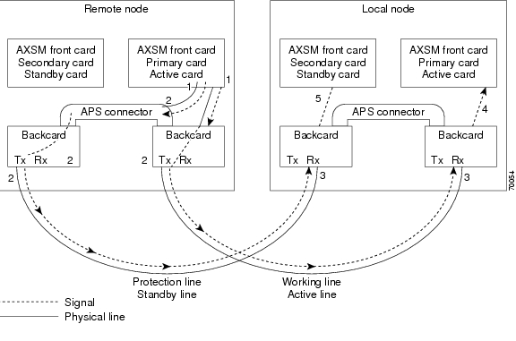
In AXSM and AXSM/B intercard APS, either front card can be active, and can be connected to either APS line through the APS connector joining the two back cards. The following process describes how intercard APS communication works:
Step 1
Step 2
Step 3
Step 4
Step 5
Step 6
Note
Figure 1 shows an example of how this process operates in a standard APS configuration, where the primary card monitors the working line and the secondary card monitors the protection line.
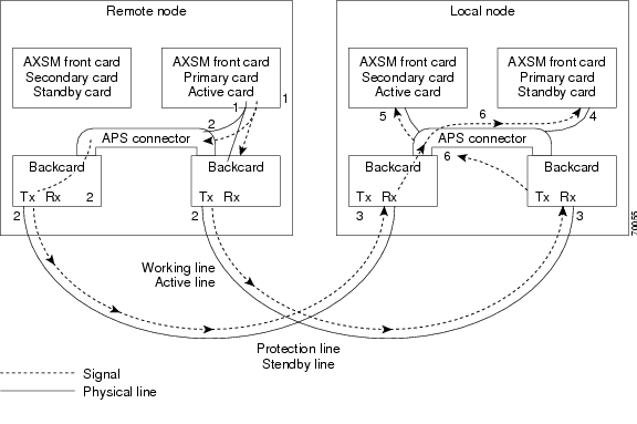
Figure 2 shows an example of how the APS communication process operates in a crossed APS configuration, where the secondary card monitors the working line that is attached to the primary card, and the primary card monitors the protection line that is connected to the secondary card.
Figure 1 Standard APS Configuration
Figure 2 Crossed APS Configuration
Line failures are always detected at the receive end of the line. This is where a switchover occurs when a failure is detected. Two different types of switchovers can occur, depending on whether the APS was configured as unidirectional or bidirectional in the cnfapsln command:
•
•
If the status of the standby line is good, a switchover from the failed active line to the standby is automatic.
Enter the cnfapsln command to enable an automatic switchover back to the working line after it recovers from a failure, as shown in the following example:
M8xx0_LA.1.AXSM.a > cnfapsln -w 1.1.1 -rv 2Table 17 describes the configurable parameters for the cnfapsln command.
If you want to manually switch from one line to another, enter the switchapsln <bay> <line> <switchOption> command, as shown in the following example:
M8xx0_node.1.AXSM.a > switchapsln 1 1 6Manual line switch from protection to working succeeded on line 1.1.1Table 18 describes the configurable parameters for the cnfapsln command.
Enter the dspapslns command to verify that the active line switched over from the protection line to the working line, as shown in the following example:
M8xx0_node.1.AXSM.a > dspapslnsWorking Prot. Conf Oper Active WLine PLine WTR Revt Conf Oper LastUserIndex Index Arch Arch Line State State (min) Dir Dir SwitchReq------- ----- ---- ----- ------ ----- ----- ----- ---- ---- ---- ----------1.1.1 2.1.1 1+1 1+1 working OK OK 5 Yes bi bi ManualP->WTroubleshooting APS Lines
Port light behavior changed in Release 3.0.00 as follows:
Port lights on AXSM /B front cards indicate the receive status of APS lines. The active front card always displays the status of the active line. The standby card always displays the status of the inactive line. If only one APS line fails, the line failure LED is always displayed on the standby front card.
Port lights on AXSMB front cards indicate the receive status of the Physical Line connected to it. For example, when APS is configured for working line as 5.1.3 and protection line as 6.1.3, regardless of which card is active, port LED on card 5 will show the receive status of 5.1.3 and card 6 will show the receive status of 6.1.3.
Note
Caution
If the active line fails and the standby line is not available, the switch reports a critical alarm.
If the active line fails and the standby line takes over, the former standby line becomes the new active line, and the switch reports a major alarm.
If an AXSM/A front card fails, APS communication between the redundant front cards fails. This can result in one of the following situations:
•
•
Use the following procedure to troubleshoot APS lines.
Step 1
M8xx0_.1.node.a > dsplnsMedium MediumSonet Line Line Line Frame Line Line Alarm APSLine State Type Lpbk Scramble Coding Type State Enabled----- ----- ------------ ------ -------- ------ ------- ----- --------1.1 Up sonetSts12c NoLoop Enable Other ShortSMF Clear Enable1.2 Up sonetSts12c NoLoop Enable Other ShortSMF Clear Disable2.1 Up sonetSts12c NoLoop Enable Other ShortSMF Clear Disable2.2 Up sonetSts12c NoLoop Enable Other ShortSMF Clear DisableIf the line in alarm is an APS line, and has always functioned properly as an APS line, proceed to Step 2.
If the line in alarm has never functioned properly as an APS line, verify that the following are true:
•
•
•
Step 2
Note
Table 19 Troubleshooting APS Line Problems Using the dspaps Command
Working
OK
OK
Green
Green
Active card is receiving signal on working and protection lines. This does not guarantee that transmit lines are functioning properly. You must view the status on remote switch.
Protection
SF
OK
Green for
AXSM/A, Red for AXSM/A, Green for AXSM/BRed
Active card is receiving signal on the protection line. No signal received on the working line.
Working
OK
SF
Green
Red
Active card is receiving signal on the working line. No signal received on the protection line.
Working
SF
SF
Red
Red
Active card is not receiving signal from either line. The working line was the last line to work.
Protection
SF
SF
Red
Red
Active card is not receiving signal from either line. The protection line was the last line to work.
Working
UNAVAIL
UNAVAIL
The card set is not complete. One or more cards have failed or been removed. See Table 20 to troubleshoot card errors.
If one or both lines appear to be bad, determine whether the working or protection line is in alarm. Troubleshoot and correct the standby line first. Replace the components along the signal path until the problem is resolved.
•
•
•
Installation and Upgrade Procedures
For information on the following installation and upgrade procedures, please refer to the Cisco MGX 8850 (PXM1E/PXM45), Cisco MGX 8950, and Cisco MGX 8830 Software Configuration Guide, Release 4, part OL-3845-01.
Upgrade Information
The upgrade appendix in the Cisco MGX 8850 (PXM1E/PXM45), Cisco MGX 8950, and Cisco MGX 8830 Software Configuration Guide, Release 4 contains the following procedures:
•
•
•
•
•
•
•
•
•
•
•
•
•
•
•
•
•
•
Maintenance Information
The upgrade appendix in the Cisco MGX 8850 (PXM1E/PXM45), Cisco MGX 8950, and Cisco MGX 8830 Software Configuration Guide, Release 4 contains the following procedures:
•
•
Upgrade Limitations
When connections are built on an AXSM_B card with software version 2.1(80) and the card is replaced with a regular AXSM, the connections remain OK. When this node is upgraded to Release 3.0.10, the card will go into a mismatch state indicating that the reserved card is an AXSM_B. See anomaly CSCdz72564 for details.
Frame Discard
Note
The order of software releases was as follows:
•
•
•
•
•
•
Documentation
This section contains important information about release notes and technical manuals.
Changes to this Document
Table 21 describes changes made to these release notes that caused the release notes to go from OL-4941-01 Rev. A0 to OL-4941-01 Rev. B0 on December 31, 2003.
Table 22 describes changes made to these release notes that caused the release notes to go from OL-4941-01 Rev. B0 to OL-4941-01 Rev. C0 on January 21, 2004.
Table 22 Changes that Caused Revision C of this Document
Information was added that describes changes in the behavior of the Frame Discard feature from Releases 3.0.23 to 4.0.12.
A Note describes an important caveat for VPCs that were added with frame discard enabled before releases 3.0.23 or 4.0.10. This note replaces the Caution that was added to Installation and Upgrade Procedures in the Revision B document.
Notes
•
•
•
Related Documentation
This "Related Documentation" section describes the technical manuals and release notes listed in the "Guide to Cisco Multiservice Switch Documentation." The guide, part DOC-7815358=, shipped with your product.
The following Cisco publications contain information related to the operation of this product and associated equipment in a Cisco WAN switching network.
Cisco WAN Manager Release 12
Table 23 lists the product documentation for the Cisco WAN Manager (CWM) network management system for Release 12.
Cisco MGX 8850 (PXM45) Multiservice Switch Release 4
Table 24 lists the product documentation for the installation and operation of the Cisco MGX 8850 (PXM45) Multiservice Switch Release 4.
Cisco MGX 8850 (PXM1E) Multiservice Switch Release 4
Table 25 lists the product documentation for the installation and operation of the Cisco MGX 8850 (PXM1E) Multiservice Switch Release 4.
Cisco MGX 8950 Multiservice Service Release 4
Table 26 lists the product documentation for the installation and operation of the Cisco MGX 8950 Multiservice Switch Release 4.
SES PNNI Release 4
Table 27 lists product documentation for understanding, installing, and operating the Service Expansion Shelf (SES) Private Network-to-Network Interface (PNNI) Controller.
Cisco MGX 8830 Multiservice Switch Release 4
Table 28 lists the product documentation for the installation and operation of the Cisco MGX 8830 Multiservice Switch Release 4.
Cisco WAN Switching Software Release 9.4
Table 29 lists the product documentation for the installation and operation of the Cisco WAN Switching Software Release 9.4.
MGX 8850 (PXM1) Edge Concentrator Release 1.2.20
Note
Table 30 lists the product documentation for the installation and operation of the Cisco MGX 8850 Edge Concentrator.
MGX 8250 Edge Concentrator Release 1.2.20
Table 31 lists the product documentation for the installation and operation of the Cisco MGX 8250 Edge Concentrator.
MGX 8230 Edge Concentrator Release 1.2.20
Table 32 lists the product documentation for the installation and operation of the Cisco MGX 8230 Edge Concentrator.
How to Find Multiservice Switch Customer Documents Online
There are several ways you can find Multiservice Switch customer documents online.
If the Part Number is Known
Use the following procedure if you know or can find the document's part number.
Step 1
Step 2
Step 3
If the Part Number is Not Known
Use the following procedures if you do not know or cannot find the document's part number.
Finding Cisco WAN Manager Documents
To find Cisco WAN Manager customer documents online:
Step 1
Step 2
Finding Multiservice Switch Documents
To find Multiservice Switch customer documents online:
Step 1
Step 2
Ordering Documentation
Note
Other Cisco documentation is available in the following ways:
•
http://www.cisco.com/public/ordsum.html
Some printed documentation is offered through the "Printed Information Ordering" site, which can be accessed through:
http://www.cisco.com/univercd/cc/td/doc/es_inpck/pdi.htm
•
http://www.cisco.com/go/subscription
•
Documentation on the World Wide Web
You can access the most current Cisco documentation on the World Wide Web at the following sites:
•
•
•
Documentation CD-ROM
Cisco documentation and additional literature are available in a CD-ROM package, which ships with your product. The Documentation CD-ROM is updated monthly and may be more current than printed documentation. The CD-ROM package is available as a single unit or as an annual subscription as mentioned above.
Documentation Feedback
If you are reading Cisco product documentation on the World Wide Web, you can submit technical comments electronically. Click Feedback in the toolbar and select Documentation. After you complete the form, click Submit to send it to Cisco.
You can e-mail your comments to bug-doc@cisco.com.
To submit your comments by mail, use the response card behind the front cover of your document, or write to the following address:
Attn: Document Resource Connection
Cisco Systems, Inc.
170 West Tasman Drive
San Jose, CA 95134-9883We appreciate your comments.
Technical Assistance
Cisco provides Cisco.com as a starting point for all technical assistance. Customers and partners can obtain documentation, troubleshooting tips, and sample configurations from online tools. For Cisco.com registered users, additional troubleshooting tools are available from the TAC website.
Cisco.com
Cisco.com is the foundation of a suite of interactive, networked services that provides immediate, open access to Cisco information and resources at anytime, from anywhere in the world. This highly integrated Internet application is a powerful, easy-to-use tool for doing business with Cisco.
Cisco.com provides a broad range of features and services to help customers and partners streamline business processes and improve productivity. Through Cisco.com, you can find information about Cisco and our networking solutions, services, and programs. In addition, you can resolve technical issues with online technical support, download and test software packages, and order Cisco learning materials and merchandise. Valuable online skill assessment, training, and certification programs are also available.
Customers and partners can self-register on Cisco.com to obtain additional personalized information and services. Registered users can order products, check on the status of an order, access technical support, and view benefits specific to their relationships with Cisco.
To access Cisco.com, go to http://www.cisco.com
Technical Assistance Center
The Cisco TAC website is available to all customers who need technical assistance with a Cisco product or technology that is under warranty or covered by a maintenance contract.
Contacting TAC by Using the Cisco TAC Website
If you have a priority level 3 (P3) or priority level 4 (P4) problem, contact TAC by going to the TAC website:
http://www.cisco.com/tac
P3 and P4 level problems are defined as follows:
•
•
In each of the above cases, use the Cisco TAC website to quickly find answers to your questions.
Note
If you cannot resolve your technical issue by using the TAC online resources, Cisco.com registered users can open a case online by using the TAC Case Open tool at http://www.cisco.com/tac/caseopen
Contacting TAC by Telephone
If you have a priority level 1(P1) or priority level 2 (P2) problem, contact TAC by telephone and immediately open a case. To obtain a directory of toll-free numbers for your country, go to the following website:
http://www.cisco.com/warp/public/687/Directory/DirTAC.shtml
P1 and P2 level problems are defined as follows:
•
•
Caveats
This section provides information about known anomalies.
MGX 8850, MGX 8830, and MGX 8950 4.0.12 Anomalies
Anomalies are organized as follows:
•
•
•
Known Anomalies in Release 4.0.12
Anomalies Resolved in Release 4.0.12
CSCdw91580 Removing SRME FC or BC causes switchover time > 250ms.
CSCdz04524 P2MP_DT: SPVC p2mp parties terminated on AXSME stays in FAIL
CSCdz66395 CIT40: OAM CC config is allowed from CLI on PXM1E.
CSCdz83876 dspclksrc displays internal clock source after switchcc
CSCea20818 mem.leak: CMtask holds ipc_get_floating_mblk
CSCea23761 Implement PCI error interrupt on pxm45c/pxm1e-8oc3
CSCea59570 Adding APS line when the stby card is not stby give wrong error mess
CSCea65791 dumpconfigs command aborted with error message
CSCea72681 Need protection to ensure that SM don't generate files to fill disk
CSCea82940 Src node found bypass for ingress & egress ports on same border node
CSCea84491 UPGRD: resetsys, err_log logged FIPC-5-EPHNDLRFAIL from pnConPro
CSCea92407 Path Alm on Protection line does not get intg. when Pri line Red/Yel
CSCea93644 CLI_CONSITENCY: AXSM-XG does not support some of AXSME commands
CSCeb03881 Backcard removal causes cc to card fail.
CSCeb06582 MPSM: abit alarm not propagated correctly for some CESM/MPSM-CES con
CSCeb13176 Incorrect reporting sequence could cause loss of diag error results
CSCeb13369 After Offline diags executes, FSM should go to IDLE, not READY state
CSCeb15291 pxm reports card in active-F and cc to card fails
CSCeb17823 Unreliable tstdelay results for axsm/B/E <--> frsm
CSCeb18768 TnCmdTsk03 exception found
CSCeb22068 Unable to cc to card
CSCeb23240 multiple APS-SF-DECL msg posted to evtlog w/o SF (BER) clearing
CSCeb23400 Need HMM error counters for QE, XIF, PIF
CSCeb25477 AXSME: dspchancnt, CLPO discarded should only show user data
CSCeb29954 Ima link failure does not reflect to the pnport resource
CSCeb31125 dsphotstandby command shows wrong info when runrev executed:frsm-vhs
CSCeb32478 taskIndex and sizeof(gSysTaskTable) expect larger range.
CSCeb34166 dspdiagcnf shows online diagnostics enabled by mistake on SM/PXM1E.
CSCeb34878 Warning needed when APS disabled on non-redundant PXM1E
CSCeb36107 FIPC-5-LINKOUTERROR Repeated Log error
CSCeb38023 switchcc caused Reset from Shell coredumps on PXM45C
CSCeb40512 delred fail for LSM in 8830
CSCeb42487 possible memory corruption issues dsperr.
CSCeb46725 tCrdmp task logged Proxy file protocol error after node rebuild
CSCeb47830 ssi exception error: snmpSA crash
CSCeb48697 dspcds shows cd type UNKNOWN when in Mismatch state
CSCeb48739 HARD: dspcd shows MISMATCH but no reserved type
CSCeb49580 HARD: no alarm cause in lower bay nbsm when rsvd for bbsm
CSCeb50179 HARD: Improper error message for addred with incomp FRSMHS2B BC
CSCeb50268 After forced switch W->P, SFBER on W does not cause W->P switch
CSCeb50631 HARD: Incorrect error message for addred 1:n bulk mode
CSCeb51038 HARD: Secondary NBSM used as Bulk and Non-Bulk
CSCeb51056 HARD:Incorrect Error Message when error in addred
CSCeb51078 dumpconfigs command aborted when there is a RPM card in the node
CSCeb51081 AXSM5 loss traffic without any alarm
CSCeb51137 Hard: CBSM in empty state when burnboot followed by addred
CSCeb51176 HARD: CBSM addred not blocked when primary SM in burnboot
CSCeb51323 SRMEB: Stats manager caused Active PXM1E reset
CSCeb51696 HARD: switchredcd and resetcd not blocked during burnboot on CBSM
CSCeb52781 SRMEB:No ERR msg while enabling SRM/SRMEB-3T3 Online Diag
CSCeb54282 HARD: dspred doesn't show Active-U during nbsm upgrades
CSCeb54310 HARD: FRSM8E1 wnt to failed state when runrev followed by abortrev
CSCeb54369 HARD: dspred doesn't show blkd for pri/sec with lower/higher version
CSCeb54823 Manual setting of CB4,CB8 allowable clock rate throws error message
CSCeb55258 Misleading error message when provisioning and not enough bandwidth
CSCeb55874 PnCcb crash cause PXM45 switchover
CSCeb55910 CCMA-4-IPCSENDFAIL message logged for AXSM-E in init state
CSCeb56175 ShmPing should exclude pinging pxm peer
CSCeb57712 ata semaphore timeout and watchdog timeout should be 30seconds
CSCeb57805 loadrev exception happens in cli cmd task
CSCeb58207 none of the bert commands executed is seen in the dsplog
CSCeb58417 clrsmcnf fails on multiple slots
CSCeb58599 MPSM8-DT: PXM45 logs Diag Error when online diag is running on STBY
CSCeb58943 Invalid SSI trace log in event log
CSCeb59779 Trap 60051 not generated for RPM_PR
CSCeb60025 switchredcd on node resets the PXM1e
CSCeb60130 HARD: secondary nbsm fail due to reset sec without prim in loadrev
CSCeb60706 PXM45/B reset due to non fatal major error core dump available
CSCeb61475 Standby PXM45A resets while getting the image from active card
CSCeb61894 LSNT:connections remain in alarm
CSCeb62400 Cannot do core hot-dump on any SM after core abort-dump
CSCeb62428 bringup tools needed for hardware debug
CSCeb62594 Disk spin down to be done only on 20G hard Disk/ add sh cmd for tmou
CSCeb62699 Axsm-xg stdby card reset and failed if keep doing delpart/addpart
CSCeb63198 MPSM8-DT:Connection routed on Prefrte but Pref-rte flag does not set
CSCeb63658 Increase HW error threshold.
CSCeb64000 switchover loss around 630ms, >250ms
CSCeb64022 Active PXM stopped responding and standby got stuck in Init state
CSCeb64756 Del/add partition causes the pnport stay in vc-failure.
CSCeb64863 Policing of 80 char limit for certain cli commands
CSCeb65427 Printf Mutex semaphore getting locked
CSCeb66181 connections on last port of AXSME/PXM1E/AXSM-XG not sent to CWM
CSCeb66476 Not able to ftp the configVerify distribution zip file to any node
CSCeb67611 SRMEB: No event logs found for srme LINK commands
CSCeb67820 CIT50:node db contains two entries with same node id
CSCeb67870 snmp Master Agent went to idle state for approx 45 min
CSCeb68355 AXSM/B does not tx RDI-P when W in LOS and P in RDI
CSCeb68706 observed message file already closed after runrev executed on frsm
CSCeb69085 need the event log. for QE1210 and CBC
CSCeb69124 Incremental files are deleted slowly when Standby is available
CSCeb69793 FI: test-13:Hard disk failure: No trap upon fault
CSCeb69978 workQPanic:HDD ISR cannot clear HDD interrupt due to PCI read failed
CSCeb70169 Stack usage exceeds threshold (70 percent): Task=tRVT
CSCeb70258 Incorrect ifName string in the atm phy trap 60373
CSCeb70361 PXM1E: pushing ACO/HIST does not generate core-dump on pxm1e
CSCeb71464 CLI for Active PXM Freeze Detection and Recovery
CSCeb71578 HARD: No switchover of 1:n red after removing primNBSM then act PXM
CSCeb72999 Reinserting AXSM-XG causes PNNI link to stay in failed state for lon
CSCeb73912 DISK Spin down to be disabled by default
CSCeb74414 avoid calling task delays in reboot (sysToMonitor)
CSCeb74423 Block switchcc/yred while stby axsm is not responding to polling
CSCeb74822 ATMizer send fails because of xmtBuff full
CSCeb75099 All traffic loss when route the conns on axsm-xg card
CSCeb76581 CIT50:pnRedman suspended at provred_persis_link_addDel
CSCeb77003 PNNI gdb enhancements.
CSCeb77459 Observed Bad CRC PDUs during the signaling packets exchange
CSCeb77524 soft reset the card when tRootTask does not get CPU
CSCeb77925 Online diagnostics on AXSM-XG causes large no of OAM cells on that
CSCeb78993 AXSM-XG: OAM Config RAM write verification should ignore misc bits
CSCeb79161 Request the correct conn DB for ramSync
CSCeb79598 STATS UPLOAD: T3 LINE - Number of Keys = 0 byte order incorrect
CSCeb80366 Implement diag changes for pxm1e-combo respin (JA removal)
CSCeb80600 corrupted stats on pxm1e -- cesm-t1e1 cards under corner configs
CSCeb80634 Implement pxm45/pxm1e diagnostics enhancements
CSCeb81314 snmpget/walk of standby SM can cause denial of service
CSCeb81848 AUTO:AXSM/AXSME fails to come up after upgrade
CSCeb83142 connection fails routing due to wrong util used at slave
CSCeb83347 printf() in cliSmEptWrite() caused flood of messages
CSCeb83949 Policing of 80 char limit for dsppnportcac and dsppnportrsrc command
CSCeb83965 Policing of 80 char limit for certain cli commands
CSCeb85464 AXSM switchredcd caused PXM to reset and coredump
CSCeb85657 P2MP parties fail to route over faked uplinks
CSCeb86666 After burnboot and clrallcnf card keeps resetting during post.
CSCeb87513 pnni link on a PXM1E with IMA backcard goes down without recovery
CSCeb88172 PXM45C keeps resetting after a switchcc
CSCec01073 FRSM HS2/B to support low speed rates like 2.4K
CSCec02957 CIT50:port stuck in provisioning after commitrev and resetsys
CSCec04064 ATmizer SAR ingress/egress path diagnostics reqd for PXM1E
CSCec04212 failed stdby PXM caused AXSM cds to go into failed state.
CSCec04754 status byte in stats file always set to 1 ERR
CSCec04902 CIT50:redman donot read > 100 records for Disk_spvc_itf_db
CSCec05278 OAM cc is not working consistently as expected
CSCec07087 PXM1E: ATLAS HMM should report errors to SHM
CSCec08533 CESM T3E3 1:1 Redundancy is not functional
CSCec10875 the first two intervals of a new connection has wrong stats data
CSCec10933 Software Err Reset coredump caused by 2 tasks hanging on a semaphoreCSCec11151 UI-S3 not locked to proper reference after inband references switchCSCec11356 LSNT:GLCNs downed for Service module cardsCSCec11994 CTC app stage spawn state machine is susceptibe to error
CSCec12108 Pnports of AXSM-XG card stay in building vc
CSCec12454 Getting the details of error log failed with wrong error message
CSCec12475 EVENT-CLEANUP: multiple IFM-5_critical errors fill in dsperrs log
CSCec12609 CIT50:several VSI sev4 error logged from act and stdby AXSMB
CSCec13851 QMC errors on AXSM1P Etch5 cards
CSCec14029 cnfpasswd command not recorded into the LOG for PXM45/PXM1E
CSCec14485 User should not be forced to enter ICR if VSVD if off
CSCec15230 Software Error Reset core dump on PXM45 node
CSCec15803 Svc number show as -1 in the partition of AXSM-XG card
CSCec16448 Can not add con with line rate on HS2/B low rate
CSCec16527 Changing maxbw using cnfpnportcac causes rsrc alloc. inconsistency
CSCec17149 Dspcons does not report AIS alarm on SPVP connections
CSCec17721 OAM cc is not working properly on axsm-xg card
CSCec20081 Add performance profiling code to CCB
CSCec20568 DCMP msg has uninitialized fields
CSCec20587 Invalid pref route value in DCMP can cause pnCcb exception
CSCec22514 PXM card reset caused by killing the telnet session
CSCec23958 Offline diags causes near end and far end pm errors on active card
CSCec24908 tsmTermdTas suspended due to invalid guard magic word
CSCec25188 MPSM8-DT: Online diag detects DataPath Test Timeout
CSCec25929 COSB stats is not cleared correctly
CSCec27723 Pnni signalling lcn reuse - pnni link cannot establish
CSCec28435 AXSME IMA port goes into vc failure after dnpnport and uppnport
CSCec28667 addimalnk for E1 path of invalid line type (E1CRC) addressloadexcept
CSCec29583 Interop of MGX 5.0 & 4.0 with PB & MPG enabled causes routing issues
CSCec33139 Not able to add redundancy between 2 RPM-PR cards
CSCec33311 blanket bugid for sprintf violations
CSCec33758 Spoke cost of destination PG should not be added to routing cost
CSCec33808 Crankback on failure of call forwarding should not be SEBI
CSCec35459 SRM redundancy not updated properly after upgrade
CSCec36965 FRSM resets due to config upload
CSCec37734 saveallcnf save config file with wrong date
CSCec38330 Send TOD update to RPM -XF cards too
CSCec39239 PBUMP: No Direct Path after Downing Trunk and Upping It Back
CSCec39798 CMTask causes an SSI exception in PXM1E running 3.0.20
CSCec40496 Dnp*ort on the Uni port on axsmxg card doesnt work
CSCec49118 Standby AXSM Failed due to IPC buffer leak on Active AXSM
CSCec49356 tVsiSlave on AXSM crashes on multiple nodes around the same time
Anomaly Status Change from Previous Release
MGX 8850, MGX 8830, and MGX 8950 4.0.11 Anomalies
Anomalies are organized as follows:
•
Anomalies Resolved in Release 4.0.11
CSCeb47830 ssi exception error: snmpSA crash
CSCeb63198 MPSM8-DT: Connection routed on Prefrte but Pref-rte flag does not set
CSCeb69978 workQPanic:HDD ISR cannot clear HDD interrupt due to PCI read failed
CSCeb88172 PXM45C keeps resetting after a switchcc
CSCeb83142 connection fails routing due to wrong util used at slave
CSCec07087 PXM1E: ATLAS HMM should report errors to SHM
MGX 8850, MGX 8830, and MGX 8950 4.0.10 Anomalies
Anomalies are organized as follows:
•
Anomalies Resolved in Release 4.0.10
CSCdv50574 delapsln produced incorrect usage statement
CSCdv69400 Enable local loop on addchanloop on AXSM-E
CSCdv87022 oam error while adding connections
CSCdw84887 AXSMXG asic registers needs to be dumped in the core.
CSCdx29779 IPC buffer corruption due to cache coherency - task suspension
CSCdx61758 ResetAtmizerOnPxm1e()/ResetAtmizerOnPxm45() use hard-coded adrs
CSCdx75573 SRME shown as SRM-T3 when it is in INIT state
CSCdx78943 AXM-XG: Dspcd displays NOVRAM Dump with Mismatched BC - axsm5
CSCdx85715 Need equivalent command of dsppnctlvc for higher level SVC based RCC
CSCdy21305 IPC memLeak in ilmiMain task
CSCdy27632 [cnfxbardmin on] does not enable PXM45A/B humvee/xbar links correctl
CSCdy37182 Incorrect dspcd Info Provided For Quad OC48 Back Card On AXSM-XG
CSCdy40482 CTC messages flooding the logs during standby reset
CSCdy61591 Enhance periodic port resynch on PXM to trigger more often
CSCdy61622 Broken HE ready pin can cause XBAR problem
CSCdy81038 dspcds shows failed backcard as ACTIVE
CSCdy82520 CIT40:several nni ports ilmi status stuck in NotApplicable
CSCdz06444 AXG4CH: XG in Failed state after resetcd with 126 EVNNI ports.
CSCdz09843 CIT40:trapSrvTask suspended due to IPC buffer corruption
CSCdz21942 AXGCH: APS1:1; Dspapsln & Dspbecnt reject with incorrect error msg.
CSCdz22884 AXGCHTM:EFCI not updated in cli dspchancnt
CSCdz23198 dspportcnt avg. counts plummets when discard occur
CSCdz23621 Z-RED:Standby RPM-XF vsi master endpoint id is not cleared on PXM
CSCdz26250 AXGCH:dsppaths -ds3 shows path N/A when -ds3 table empty
CSCdz43418 P2MP_DT: addparty create svc UBR instead of CBR with BCOBA
CSCdz45007 AXSME-16T3E3 failed when redundancy is added.
CSCdz47627 PXM45/B/C does not come up after inserting HDD backcard
CSCdz61310 1e: DT Error messages appears on all Xterm sessions
CSCdz63826 P2MP_DT: Nodal conn limit can be exceeded when p2p and p2mp combine
CSCdz65649 1e: DT addapsln should not be allowed if aps mini bkplane is not pre
CSCdz65654 Double free memory problem in function pnni_svc_send_msg_to_sigapi()
CSCdz72159 SYSTEM:Standby PXM should check Active PXM heartbeat
CSCdz79515 burnboot should not be allowed on a downed card
CSCdz80353 memShow on the pxm1e displays a negative number.
CSCdz81163 CLI needs to support formatting for 64 bit objects.
CSCdz81341 Failed to sync up with one PXM45 node-CUT dir not found on this node
CSCdz81780 Memory Usage: Manage through memory pool instead of global
CSCdz82259 In NCDP mode t1 and e1 reference present at the same port 7.35
CSCdz82315 Junk output sent to all CLI by addred
CSCdz83401 dsppnni-election should show active peer group leader node name
CSCdz87239 addred on MGX gives an error message
CSCdz87255 File open doesn't return error for non existent file.
CSCdz90184 VsiErr and VSI_VRM_TRACE does not work on standby PXM45
CSCdz90394 Enhance display of dspnwnodes to include in use field
CSCdz90584 UPGRD: PXM45/B active/stdby in minor alarm after upg from pxm45A
CSCea01025 DIP: tca option prints garbage for SONET line
CSCea02816 UPGRD: at runrev on pxm45, error log shows pnCcb task is not owner
CSCea03515 1e: DT dnport/upport causes high CPU utilization on the node
CSCea04132 1e: DT unwanted messages after clrsrmcnf for SRM-3T3
CSCea04389 ipc name server errors logged on a node
CSCea06889 Even though the slot was empty, it gave error while cc
CSCea07573 Axsmxg connection stat values are incorrect
CSCea07599 Static and Statistics Memory partitions are low in AXSME 4.0 Image
CSCea09461 PXM1e: Reducing port rate by cnfport got rejected with VSI error
CSCea10567 Need to warn/block reset single PXM with disk hw failed
CSCea11030 snmpSA task is stuck- CWM doesn't get traps
CSCea11335 SNMP request caused an exception
CSCea11689 MGX sends card removal trap with alarm severity of 8 - s/b 2
CSCea12511 dspvsiparts show partId as 0 when partId is 1
CSCea13194 REG4: dspchancnt X -r 1 cannot be quit 1e: DT
CSCea13539 CTD & CDV incorrectly copied in atmSoft_getAltenateAdminWt()
CSCea13996 UPGRD: at loadrev, stdby pxm reports SFP mismatch
CSCea14630 IMA bandwidth change not reflected in PNNI
CSCea15325 1e: DT REG4: one-way switchcc loss > 520ms on 8-oc3
CSCea15665 UPGRD: tDbgInTask/tDbgOutTask get TID 11 when telnet from w/in node
CSCea16704 resetcd shows Standby card not ready/available card not redundant
CSCea17820 Null saved ttl i.e. ptr log cluttering CC module
CSCea17835 SHM<->XG SFP: SHM doesn't make secondary cd actv on addred actv mis
CSCea18042 PXM crashes after start traffic between 2 RPMs in the shelf
CSCea19434 UPGRD: during upgrd, pnCcb reports AUDIT release error
CSCea20454 PXM1e: 2cells/s AIS on Swth side Tx after get LMI-Abit frm Feeder
CSCea20600 pnPnni is not the owner of the block
CSCea20706 Require user confirmation for cnfpath -width change
CSCea21717 AXSM with policing enabled, expectation is that gcra1 is enabled
CSCea21837 Cant disable Frame discard parm on VPCs
CSCea21991 1e: HARD unable to upln2.5-2.8 if 8oc3 goes UNRES during h/w upg
CSCea23516 Congestion value help doesn't reflect the new acceptable values
CSCea23534 GDB Syncup with firmware files.
CSCea23761 Implement PCI error interrupt on PXM45/C/pxm1e-8oc3
CSCea24010 OAM error: OamLpbkHandler seen during upgrade
CSCea24098 1e HARD: SHMA-4_API_SEND_ERR on active PXM1E after switchcc/upgrade
CSCea24732 FRSM12:lmiXmtUpdateStatus inside shellcon flag control
CSCea24948 Hotstdby:dsphotstandby check IMA DB record on non-T1E1 cards
CSCea25138 SCM Debug Enhancements for collecting info on Poll/Htbt failures
CSCea25406 UPGRD: addaps on Jcombo, SHMA-INTERCD-APS-RPT logged to error_log
CSCea26305 Add explanation to usage of adding part id to a controller
CSCea26569 Connection show wrong preferred route status after prefroute changed
CSCea26816 1e HARD: SSI-5_DOSFAIL error due to task cutVTask
CSCea26821 1e HARD: tRed error, possible corruption for redTable after abortrev
CSCea27324 1e HARD: NCDT-4-ADDVC_FAIL on standby PXM1E on configuring ncdp
CSCea27538 Diag image hangs on DPDC CPUB
CSCea27656 Dax con: need to update fail cause code if slave is LOS
CSCea27781 cnfconsegep on leaf svc endpoints displays root endpoint vpi/vci
CSCea27803 tstpndelay fails to work on svc leaf endpoint
CSCea27807 BRAM corruption on PXM45B after power cycle and during runtime
CSCea28523 1e HARD: FILM-5-FWRITE_FAILED should not be logged as an error event
CSCea28822 1e HARD: RED-5-SEND_MISMATCH upon removing active sec FRSM-2T3 BC
CSCea28840 1e HARD: downLoadBram failed after remove act pri FRSM-2T3 BC
CSCea28863 Enhance SyncRam to support Max Outstanding IOV Buffer from 8 to 16
CSCea28998 Need to initialize response message in cli2shmCmdIf()
CSCea29118 Place Holder to remove ability to enable/disable sfp security check
CSCea29984 Resource Reservation phase II checkin
CSCea30418 Need to add cefcLastClearConfigTime in the shelf generic files
CSCea30694 dspconsegep on SPVC endpoint show incorrect segment endpoint status
CSCea31745 CIT40:4 NwClockMgr log should be reduced to lower severity
CSCea32116 1e HARD: Autocard and dbClnt event log after delred 1:1 FRSM VHS
CSCea32276 1e HARD: VSIS-5-VSIERR event log due to CMTASK
CSCea32283 1e HARD: SHMA event log due to task tmon on PXM1e-8oc3 and 8E3
CSCea32296 1e HARD: pcemaGETLINFormPort error due to task FTM on PXM1E-4oc3
CSCea32660 Handling of entries in Provisional tree on deletion of part. on SM
CSCea32763 1e HARD: NCDT DISABLE PORT event log when all ncdpports are dn PXM1e
CSCea33031 1e HARD: SHM API Err due to task pcemaSyncTash on PXME-8oc3
CSCea35486 CIT40:some filters for dsppnsysaddr do not work
CSCea37542 REG4: AXMXG-CH dspportcnt syntax is incorrect
CSCea38021 dspcd does not report alarm of standby PXM
CSCea38347 cnfdiagall is done enabling diag for all slots, enables srm3t3 not s
CSCea38739 REG4: clrimadelay failed when IMA group in version fallback
CSCea38855 AUTOMATION: svcblock is broken
CSCea39016 dsppnni-svcc-rcc shows wrong information
CSCea41058 Size of Replicate Directories array must be dynamically calculated.
CSCea41104 set on ChanRowStatus to notInSerivce on down conn does not throw err
CSCea41573 Avoid memory leakage in trapserver for large traps
CSCea41723 Add ICR range check to SES CLI interface (cnfcon and addcon)
CSCea41802 dspdeverr shows redundant info on every screen of a multi-screen o/p
CSCea41991 switchapsln display need to be enhanced
CSCea42097 Resource Reservation phase III checkin
CSCea42240 [SysDiag]: sysdiag clears self diag errors while going STBY->ACTRDY
CSCea42581 Copy OK:65552 bytes copied popup on AXSM telnet session
CSCea43402 pxm1e inserted caused clkalms but dspclkalms result in error message
CSCea44266 REG4: Unknown reserved st. of Combo back card causes APS failure
CSCea44644 PXM45: ping command does not default to 5 and no No. of packets opt.
CSCea45267 REG4: Routing cost not update after conn reroute due to vpi mismatch
CSCea45702 dsptopolinklist displays rmt PnPort ID as a huge -ve no.
CSCea46427 PXM45C/PXM1E-8OC3: HW WD Timeout is not the same as on PXM45A/B
CSCea46677 Non persistent pep code cleanup
CSCea47481 after switchover data stopped on a pvc between two nodes
CSCea48409 dspcons -rteid has incorrect syntax help
CSCea49519 Do not update ptse flush to standby for topo nodes
CSCea49615 UPGRD: on card bringup in 8830 node, srmOnlineBotBay task logs Error
CSCea49652 UPGRD: upon switchcc on pxm1e, ACAR-2-DBINIT from autocard task
CSCea50382 ATMC-5-INTERNAL WARNING need to be cleaned up
CSCea50527 EvtLog:DB2S-4-DBSVR_DOS_FAIL logged on switchcc
CSCea50686 EvtLog:PXMC-4-GENERR message logged after switchcc
CSCea50748 Resource Monitor Files Checkin
CSCea51139 REG4: FRSM12: tstcon/tstdelay result shows 5 channels
CSCea51508 Telnet server enters infinite loop waiting on input
CSCea51517 Supported SM cards need Core Hot Dump feature
CSCea51520 SSI IPC tracing on LCNs, Epids and Card-to-Card data is broken
CSCea51928 cnfdiagall enables diag for empty slots 31 and 32
CSCea52204 pxm45 exception due to a boundary case on conn upload file cleanup
CSCea52282 UPGRD: event_log get conns in CPRO-4-GET_LCN_FAILED for axsmxg
CSCea53625 UPGRD: upon loadrev, the pxm logged RESY-5-BLKZEROPEP (dsplog)
CSCea54679 Secondary clock status showing OK,clock reason is unknown reason
CSCea54763 UPGRD: ssiChunkPoolsShow gets neg. value for nb_alloc_ok, nb_free_ok
CSCea54830 cnfconsegep response dump outputs corrupt screen
CSCea55999 dspload shows service category corruption for partitions
CSCea56491 Link Invalid trap for uplink not include correct local port#
CSCea56548 Clear IP interface stats counters
CSCea56906 PXM45 reset due to pnCcb task crashing
CSCea57084 cnfclkparams does not behave as intended
CSCea57096 if path is up, conn configured but not bound the drop all msgs
CSCea57626 Placeholder for P2MP on PXM1E Feature Checkin
CSCea58703 Debug congestion msg statement is spewed to screen during SVC test
CSCea58817 dspdiagstat failed counter not reset properly
CSCea58913 UPGRD: upon burnboot, axsmxg comes up active/active exp. active/mism
CSCea59011 UPGRD: node gets error_log of RESY-5-PEPNOTEXIST, no entry event_log
CSCea59054 SNMP subagent is not registered leading to GET failures
CSCea59170 UPGRD: upon switchcc on pxm1e, ACAR-2-DBINIT from autocard task
CSCea59289 addchanloop VP greater than 255 doesn't work on NNI link
CSCea59612 dnpnport/uppnport caused all links to go to ILMI failure
CSCea59652 Offline diagnostics fails on AXSM/E card
CSCea61569 CUT: memory leakage
CSCea63353 Dynamic memory corruption - AXSM/B
CSCea63712 Send proper Severity Value in PXM45/PXM1E/AXSM and all traps
CSCea63966 Post passed even PXM boot from wrong boot rev
CSCea64148 Resource Reservation phase III implemented for critical tasks
CSCea64332 Handle sysClkTick wraparound in SSI
CSCea64399 REG4: Pref route: Num of network node poorly display
CSCea64478 Node unreachable: memory is held by pnni tasks
CSCea64753 Event log entry for RDI-L needed
CSCea64778 dspadjlnalmcnt -intvl option should be removed
CSCea64785 AXSM Conn. database corrupted after disk corruption
CSCea64808 ssi exception generated by HwMonitor on AXSM
CSCea65228 REG4: AXSMXG-CH comes up as a Active-F/Active after resetsys.
CSCea65471 Backend functions used by k_entity_get should set errno
CSCea65604 REG4: PNNI task is suspended due to software exception
CSCea65605 limit max cref count in RM to 27000 for PXM45
CSCea65768 dumconfigs executes some macro commands which are not supported on p
CSCea65819 PXM failed due to event log disk write problems
CSCea66038 Provide mechanism to track buffer leak for all SRs applications.
CSCea66438 Bert is enabled on the FRSM8T1 line even though no bert running on P
CSCea66540 REG4: Rrtcon causes traffic outage for extended period of time
CSCea66920 IT/AT: incorrect range/functionality for dspslotlink & dsperr
CSCea66971 Log floods with VSI_4-RMBWCACError
CSCea67065 Connection mismatch due to bulk sync not working correctly
CSCea67241 Port rx RDI alarm on virtual channel
CSCea67896 after switchover standby came up in mismatch state with trunk bc
CSCea68727 Incremental files are not getting deleted from couple of nodes
CSCea68798 Telnet to a node fails with the error indicating No Resource
CSCea68950 CIT40:pnCcb suspended at atmSoft_openSvcParty
CSCea68959 CLI: telnet need to setsockopt SO_KEEPALIVE
CSCea68972 CIT40:port stuck in down in progress with dangling svc
CSCeb69150 PXM reports port alarm on AUSM-IMA card after clearing of line alarm
CSCea69245 pxm1e clock is stuck in interface does not support clockin state
CSCea69606 SRMs in reserved state after clrsrmcnf
CSCea69620 telnet to lan interface fails time to time
CSCea69772 number of pnports is -7
CSCea69946 tracking bug for hw alms issues at customer site
CSCea70636 It is possible to download ver 3 bootcode to Broadcom PDC flash
CSCea71135 Reroute on AXSM-XG caused tVsiSlave toget suspended
CSCea71197 SSI Sync Timer not initialized
CSCea71360 AXSM-XG Cell Bus SAR Reassembly status shows discards occasionally
CSCea71811 pxm1e reporting wrong state of srm-#T3 of slot 16
CSCea71884 Evt Log indicates error, unable to open/create diag log file
CSCea72069 Ports went to building vc after reinsertion of AXSM cards
CSCea72190 deletion of SCT files causing errors, and not updating properly
CSCea72419 SSI exception in SAR ISR caused card reset
CSCea73159 AXSM-XG memory map setup incorrectly
CSCea73315 AXSMXG:Ifname scheme needs to be changed as per CWM req.
CSCea73429 SysDiag causes memleak on Active PXM45 card
CSCea74070 PXM45B switchover happened automatically on MGX8950
CSCea74091 REG4:Reseating both pxms on MGX 8950 freezes the nodes
CSCea74178 REG4: reset SM (Empty) and switchover on PXM1E, showing Failed/Empty
CSCea74359 SHM Fatal/Non-fatal report APIs - pcema(PXM Connmgm)
CSCea74366 SHM Fatal/Non-fatal report APIs - PXM Connmgm-VSIS
CSCea74371 SHM Fatal/Non-fatal report APIs - IP Name Server
CSCea74373 SHM Fatal/Non-fatal report APIs - pcpro
CSCea74378 SHM Fatal/Non-fatal report APIs - SCT File Manager
CSCea74459 Invalid entries in atm_connection for SES endpoints
CSCea74882 Connections fail to route due to svcc-rcc is not up
CSCea75170 parent change trap not sent
CSCea75353 DEV: SPVC fail to establish w/ lctd set to sum of trunks ctd
CSCea75375 CIT40:IPC 8k buffer low and congestion
CSCea75576 pep stuck in vsi-in-progress
CSCea75640 dead code causing confusion - need to be removed
CSCea75675 IPCONN Suspended & PXM45B stuck in reboot for long time
CSCea76411 sysBlinkLedOff leaks 48B of memory every time called
CSCea76798 SCT file for AXSM-XG
CSCea76869 REG4:nbsm dax conns triggers nni routine pep_p
CSCea76994 Entity MIB Changes to support OSMINE certification for ENV devices
CSCea77282 CIT40:pnCcb suspended at resyncGetLegFromSvc
CSCea77528 SRME standby does not initialize properly
CSCea77597 SSI: invariant checks flood event log
CSCea77946 flood of trap 70103, received 1197 in 5 minute period
CSCea78045 AXSM2/B offline full coverage diag always fail
CSCea78166 Connection trap (for some) implementation does not match definition
CSCea78204 CIT40: SES node stays in mem and leg congestion
CSCea78695 REG4:DBSYNC warnings in dsperrs when resetsys
CSCea78828 Both PXM45B failed when upgrading
CSCea78828 Both PXM45B failed when upgrading
CSCea79827 UPGRD: Double free of IPC buffer after IPC reply failure
CSCea80248 CLI task suspended and PXM45 switched over
CSCea80544 UPGRD: remove active pxm45C triggers Exception at interrupt level
CSCea80608 LSNT:stats files go to badfilelist
CSCea80655 Node doesn't recover from congestion during conn reroute
CSCea81631 dspalms cli on PXM45 is not showing anything
CSCea81721 UPGRD: online diag reports, but HMM does not reports card problem
CSCea81791 Need high priority queue for mgmt traffic in Europa SAR
CSCea81820 Primary RPM not reset after IPC seat deletion & secondary take over
CSCea81899 LSNT:error writing file.error 0x38801c for RPM-PR
CSCea82079 optrte produces messages in the log
CSCea82467 rtopt is done even for NNI port
CSCea82643 PnSscop holding sarMgmIpcRxBuffer
CSCea82849 function returning values other than function type
CSCea82887 starvetask error: SCM Leaking Memory(FixDone: Debug Code Added)
CSCea82940 Src node found bypass for ingress & egress ports on same border node
CSCea83015 Active AXSM failed to operate and standby card went to failed to sta
CSCea83031 UPGRD: At runrev on AXSM-OC3B,Sync Timeout Handler fail
CSCea83188 wrong error message when cellbus clk is configured with autosetting
CSCea83257 The ENUM_errCode_genConnErr (117) is not unique/specific
CSCea83345 Active PXM gets reset while core hot dump is aborted on SM
CSCea83402 introduce event logs in atmizer host code
CSCea84077 dsppnni-node-list shows 2 (instead of 1)for the local node
CSCea84180 XBAR: AXSM-32T1E1-E cards not added in the list of serial bus cards
CSCea84287 PXM1E went to idtmon
CSCea84304 REG4: both cards reset after runrev;core dump found
CSCea84616 releasing svc but svc or call id is NULL
CSCea84711 error log - vsi state FULL but peer leg is NULL
CSCea85031 node rebuilt again after a resetsys was executed
CSCea85150 AXSMXG:dspver should show AXSM-XG under card type.
CSCea85217 popup message on telnet session atmSig_build_snmpTrace:port_id..
CSCea85222 Raise the task priority of legacy apps running on the PXM
CSCea85433 Need to enable HMM interrupt for Scheduling, QE, XIF and PIF
CSCea85629 LMI protocol should exchange logical slot/port info
CSCea85850 Leak: Memory leaked by scm message send by shm2ScmCnfPollParms
CSCea86041 MPG preferred route failure. Connection in fail state
CSCea86144 PXM switchover every minute due to pnCcb crashes
CSCea86474 rmmSendCTCMsg task not applicable for PXM1e targets
CSCea87103 Europa CTT corruption during up/dn pnpports
CSCea87281 tstcon fails if more PVCs are added between PXM1E and VISMs
CSCea88075 add diag. codes to collect overflow stats.
CSCea88905 SM needs to check for PCR >= ICR >= MCR when configuring conns
CSCea89254 AXSM-E Local Channel Loopback not functional
CSCea89407 Investigate Atmizer PCI freeze
CSCea89735 dsplns repeatedly dsp all lns when APS 1+1 lns configured only
CSCea89755 Should not consider spoke cost when BN path does not exist
CSCea89860 near-end CurrentPCVs and CurrentPES are not incrementing
CSCea90166 addred fails with back card mismatch error
CSCea90213 Trap server need to map Severity values from apps/SMs
CSCea90476 dspcdalms is not reporting correct alarms after upgrade
CSCea90885 VSI Slave Add control port failed error event msg after addcontrolle
CSCea91209 dspchancnt does not work for p2mp connections
CSCea91227 FRSM-2CT3 card stuck in Standby state
CSCea91250 Online diag flr (cc con flr) of AXSM-E OC3 - no ind in dspdiagerr
CSCea91362 VPI overlap causing dnport failures.
CSCea91382 dspchancnt on pxm1e does not work for control VCs
CSCea91807 PNNI task pnSptAw is running away
CSCea92020 Active PXM gets reset after issuing core hot-dump on service module
CSCea92539 pnCcb Crash
CSCea92707 possible of NNI resource leak !
CSCea92832 ports in down in progress, node snmp unreachable
CSCea92851 axsm and pxm cards reseted by shm
CSCea93216 Incorrect node entry in persistent topo db
CSCea93238 Messages pops up on MGX login window
CSCea93470 pnni connections not shown in dspcons after image upgrade
CSCea93772 Event Log does not show correct info on clk switchover
CSCeb00556 Reject backcard reservation from non-active SMs
CSCeb00576 Backcard unreserve should clear the reserved BC NVID
CSCeb00707 No alarms on VNNI ports
CSCeb01093 PXM45C resets with Work Queue Panic with no coredump
CSCeb01727 Static files should be deleted from standby PXM on clrallcnf/clrsmcn
CSCeb01883 need warning message about conns derouting when dnilmi via cli
CSCeb01891 resetcd fails, log shows task starvation with tNetTask running away
CSCeb01960 CIT40: Cache Exception Handler corruption in Backup Boot in PXM45C
CSCeb02143 Evt Log: SYS-4-ERR SysDiagTimerStop error messages logged during dia
CSCeb02341 Enhance DataXfer connection to allow register up to 16 windows.
CSCeb02467 cc: 1. Zero bytes to be written 2. static mem free event.
CSCeb03383 IDE perftest leaks file descriptors & memory
CSCeb03759 AXSM-XG needs to set reassembly timeout to a reasonable value
CSCeb03930 cpro code review for double commit
CSCeb03966 wr mem fails w/ startup-conf file open failed (Unknown error 1785358
CSCeb04690 link went down after delaps on secondary card
CSCeb05265 AXSME/XG should also use cutwAlarmFileWriteLatest for incr files
CSCeb05876 sscop stuck in reset state
CSCeb06087 RPM-PR should not switchover to redundant if reset flag is disabled
CSCeb06188 SNMP GetNext on Feeder table returns multiple dup responses
CSCeb06258 HARDENING: QE SAR INVMAGIC changes
CSCeb06552 New API to query for Max Elements can be sent at an instant.
CSCeb07265 Semaphore not returned in config upload
CSCeb07649 File created by Sysdiag can grow without limit
CSCeb07718 node rebuilt again after a resetsys was executed
CSCeb07879 received message the alternate tbc is not of combo back
CSCeb07963 HARDENING: Coredump should identify incomplete core and log the same
CSCeb07986 AXSM pair reset w/ DAX conns caused loss of telnet/console port acce
CSCeb08124 CCB task is stuck on ssiTaskDelay after large config reload
CSCeb08242 clrsmcnf takes 150+ sec and always failed/aborted for the 1st time
CSCeb08282 AXSM-E response to CLI dspchanloop not showing loopback type
CSCeb08420 empty slot check for cc command broke AXSM and AXSME builds
CSCeb08432 ciscoWANSscopLinkChange trap being sent out on standby PXM (dropped)
CSCeb08814 AXSM-XG went to Active-F due to scheduling U4 control parity error
CSCeb09028 HARDENING: SM Core configuration needs semaphore protection
CSCeb09216 In error case, spvc leg may be freed without pep indication
CSCeb09273 Need shellcon command to see total count of ais
CSCeb09620 CUTS timers are not working properly after switchovers/switchredcds
CSCeb10288 cc command modification doesn't use SHM API function to get card stat
CSCeb10455 Temporary disable HMM for port device
CSCeb10713 Line never out of SF
CSCeb11493 Inconsistent routing cost
CSCeb11785 P2MPJ loaded addparty failed with SPI PATH and OUT OF LEAF error
CSCeb12259 DISK: Disk goes to busy state
CSCeb12866 Online diag failed with Utopia test receive timeout
CSCeb13117 pxm45 online diag potentially leak ipc on standby
CSCeb13164 pxm45 online diag starts offline timer when swithcc to active
CSCeb13227 pxm45 online diag enhance:add diagHelp, appropriate err checking.
CSCeb13255 connections are derouted before the expiration of sscop timers
CSCeb13272 P2MPJ pnRedman exception triggered during delparties
CSCeb13320 CBM1/CBM0 Ingress Parity errors on PXM
CSCeb13364 CLI clrdiagstat does not work on the standby card
CSCeb13569 replace ssiRamIovCurMaxElementsGet with new SSI API (in all axsm app
CSCeb13967 PXM45 reset due to Tlb Load Exception
CSCeb15236 traps 60103, 60129 received with trap number=-1 at NMS
CSCeb15251 Checkin real issues found during code-review and code-coverage
CSCeb15425 linkinvalid trap missing
CSCeb15476 tstconseg not working properly with option num
CSCeb15543 config files creation fails on pxm
CSCeb15642 addaps line is allowed on AXSM-OC48/B while in AXSM-A OP mode
CSCeb16085 clear static variables and avoid static memory fragmentation
CSCeb17103 null ptr/malloc and free mismatch
CSCeb17121 P2MPJ: node reset when switchcc as subAgent fails to resolve EpId
CSCeb17400 config upload file missing cwaChanIntAbrVSVD and cwaChanExtAbrVSVD
CSCeb17732 Possible fragmentation caused by small mem allocations from heap
CSCeb17785 AXSM-XG switchover during re-routing with dn/uppnport script
CSCeb17786 Popup from CUTV Event Handler
CSCeb18012 cema should revert back reservation/unresv if SHM reporting fails
CSCeb18167 P2MPJ PXM1E-IMA P2MP addparty failed with SPI error
CSCeb18178 add debug counter for AIS send recv from controller
CSCeb18197 Standby card resets thrice and goes into Fail state after resetsys
CSCeb18630 ncdp_db gets updated during loadrev state and blocks runrev
CSCeb18702 cnfpri-routing command should be blocked if p2mp queue is not empty
CSCeb18768 TnCmdTsk03 exception found
CSCeb19078 dspcon for prefer route should show route cost as N/A be it SPG or M
CSCeb19177 Online diags: Hard disk access too frequent. Change to once in 15min
CSCeb19444 pnports in down in progress
CSCeb19644 AXSM/E does not detect and discard OAM cells w/CRC error
CSCeb19917 default val incorrectly specified in cnfintfcongth help syntax
CSCeb20060 SNMP: change binary to mutex semaphore
CSCeb20066 Temporary buffer congestion can cause Diags to stop running
CSCeb20096 cnfsscop command doesn't have parameter range
CSCeb20387 CHNK_XNOT_USED error on standby PXM after switchcc
CSCeb20411 multiple PARMINVALID errors on PXM1E node
CSCeb20426 Memory Congestion on MGX (PXM45)
CSCeb20445 Removal of OC3 uplink port on pxm45 boards
CSCeb20461 pnport remain in vc failure
CSCeb20464 multiple VSIS errors on PXM1e nodes
CSCeb20522 EvtLog:switchcc-CTC-4-EVTSENDTOSTMCHN error message
CSCeb20534 EvtLog:switchcc-MCAST-4-CNFSNMP_ERRORPA
CSCeb20553 EvtLog:switchcc-PROO-4-soPRerrEv
CSCeb20707 Upgrade of SM is locked while the SM remains in active-U state
CSCeb20746 Limit telnet node-to-node to one hop
CSCeb20884 Resetting Service modules caused a switch PXM core
CSCeb21825 NamTask occupy the memory and cause the pnport stay in down in prog
CSCeb22799 All AXSME cards show Resource Alarm Major
CSCeb22910 PXM1E standby card failed with Troot task exception after upgrade
CSCeb23245 AXSM failed after upgrade frm 3.0.20.100 to 4.0.10.2P3
CSCeb23443 Possible truncated/misformed IPC message cause errmsgs on RPMXF
CSCeb23611 IFM_LOG string error in atmcoreifcAct20
CSCeb24166 CLI-IN to wait till the cmd task is done and not accept any cmds bet
CSCeb24722 AXSM-XG: memory leak in AXSM-XG OAM
CSCeb25248 runrev failed after CESM is deleted from 1:n redundancy
CSCeb25592 AXSM-XG: cema error logging enhancement
CSCeb25839 pxm45 online diag: potential LCN leak
CSCeb26030 Chg reqd to prevent unintentional delpart trigger.
CSCeb26052 after runrev both PXM1E reset
CSCeb26138 Remove some commands which are not required
CSCeb26579 VISM <-> SAPI communication lost during VISM reset
CSCeb27325 Unwanted ssi_ipc message on AXSM-XG console
CSCeb27605 Need matching handling of IPC_CRIT_PRI ipc msg on Sar side
CSCeb27631 local variable returned in cwspConfigTable
CSCeb28248 Memory leak due to frequent PTSE refreshes
CSCeb28420 EvtLog:emSyncHumveePort fail messages in log
CSCeb28664 Inserting PXM1E/PXM45 slowly cause incorrect HW initialization
CSCeb28869 Trap Freq test reports failures (or success) twice for each run
CSCeb29029 Enhancement changes for config upload hardening
CSCeb29267 Memory allocation failures at AXSME card
CSCeb29794 RMON related event log messages should be at a higher severity
CSCeb30173 AUTO:tmOn command causes pxm1e to pause indefinitely
CSCeb30373 AXSM does not correctly report sonetPathIntervalESs object
CSCeb30550 NNI links on PXM1E went of resources with only few cons routed
CSCeb30643 Standby PXM got stuck in INIT state: link topo failed to access data
CSCeb30953 CLI session does not timeout after saveallcnf
CSCeb31839 Inconsistency in line alarm reporting with dspcds and dsplns.
CSCeb32256 SARSNDERROR filling up the dsperrs log
CSCeb32410 FM_OPEN errors are filling up the error log
CSCeb32489 VxWorks timer fails after 466/496 days
CSCeb32512 C:CUT directory is synced with standby
CSCeb32523 VISM clk ports was not correctly handle on PXM
CSCeb32526 need to enhance CBC ingress parity error logging
CSCeb32527 Non Fatal IE handling in RELEASE msg. needs to be fixed.
CSCeb32578 Node CPU usage >90% w/mpsm155 sanity - console/ethernet unresponsive
CSCeb33456 Change code handling for RPrime search for p2mp
CSCeb33695 Fix the ssiClkTickGet timer wraparound leading to file create failur
CSCeb35085 Getting error on cell bus caused card to go to failed state
CSCeb35244 REG4+: Software err reset core dump generated twice within 15 min.
CSCeb35373 Need more defensive code for prevent invalid address access
CSCeb35412 VNNI link stuck in onewayoutside status
CSCeb35848 Tracing/Debug code for SHM Hardening effort
CSCeb35966 AXSM/E card core-dumps, fails and DB corruption observed
CSCeb36159 HW and card State Alarm on Stdby pxm1e combo after loadrev
CSCeb36393 send trap to indicate the enabling and enabled states of the switch
CSCeb36526 LSNT:RVT process stuck in init state after switchcc
CSCeb37438 PTSE flag changes do not get updated at the receiving nodes
CSCeb37714 svc_cac if_indexs missing in PNNI CC CF file
CSCeb37862 topo gw stuck in enabling state
CSCeb37912 AIS status is not getting updated on the VUNI port
CSCeb38038 dspcon shows con in pref when its not in pref route
CSCeb38189 could not cc to any slot after the switchcc hang problem
CSCeb38985 MOC error caused ILMI failure on AXSM-XG card
CSCeb39148 Offline diag fails with Data path test receive timeout
CSCeb39202 CWM request to reduce traps sent from the switch
CSCeb39220 subagents failed to register
CSCeb39242 Possible memory leaks in SCM.
CSCeb39866 IPC: IPC data buffers should be cache aligned
CSCeb40302 after node rebuild frsm-2t3 card came up in failed state
CSCeb40512 delred fail for LSM in 8830
CSCeb40612 reset of active AXSM in red pair - RM not freeing resources
CSCeb41273 cnfdiagall command does not work after cnfdiag <slot> used
CSCeb42454 CMSC fails to get stats file on 8830 PXM1E with long node name
CSCeb43141 PnCcb is hogging the node after downing the nni port and uni port
CSCeb43213 subagent did not come up on axsmb after upgrade
CSCeb44169 SRCV task is at 60% with a very high stack usage
CSCeb44780 FI: ATM device egress memory fault is not detected by online diag
CSCeb44925 TrapCl errors logged on stdby
CSCeb45101 switchcc shouldn't be executed when stdby pxm has a hardware alarm
CSCeb45254 SRMEB: Add/Del line loop cause APS failure
CSCeb46615 node not shown in dsptopondlist
CSCeb47263 dangling sessions on AXSM cards
CSCeb47692 TrapSrvtask holding memory
CSCeb47749 PCI2PCI Bridge in reset caused sw to lock up
CSCeb47823 unable to cc to Active/Secondary FRSM when Primary slot is empty.
CSCeb48179 Pxm1e stuck in dead lock after running addlink/dellink script
CSCeb48679 AXSM/E UNI port passes F5 Segment Loopback ID=0 cells to n/w
CSCeb48715 AXSM/B UNI port passes F5 Segment Loopback ID=0 cell to n/w
CSCeb48721 AXSM with policing enabled, expectation is that gcra1 is enabled
CSCeb49058 DS3 int on AXSM-B/AXSM-E/PXM1E alm. clear int time is incorrect
CSCeb50248 Shm reset standby PXM1e while it was in offline diag
CSCeb50728 AXSM with policing enabled, expectation is that gcra1 is enabled
CSCeb51610 PXM1E UNI port passes F5 segment loopback ID=0 to n/w
CSCeb51648 The detail QE1210 Log. is needed when SCM poll fails
CSCeb51676 EVENT-CLEANUP:multiple ATMC and ATMS errors fill in dsperrs log
CSCeb51978 Unable to login to Active PXM
CSCeb52114 Wrong trap for sonet path in alarm for AXSMXG card
CSCeb52766 LSNT: PXM45 in Active-F state, mainproc1 suspended
CSCeb53193 HARD: Prim SRM in fail state since tRed instructed to go to fail
CSCeb53201 HARD: RevChgLock corrupted and locks upgrade commands
CSCeb53689 SSI-3_Exception after resetsys
CSCeb54108 Standby PXM coredumps due to pnRedMan software error
CSCeb54229 SHMA-7-NFATAL_MAJ_ERPT filing up the dsperrs log
CSCeb54825 Persistent RM alarms generated due to SSI static med threshold cross
CSCeb55365 HARD: pseudo reserve code from AXSM to RPM does not change
CSCeb55874 PnCcb crash cause PXM45 switchover
CSCeb56475 tRoot Enhancement
CSCeb57712 ata semaphore timeout and watchdog timeout should be 30seconds
CSCeb58943 Invalid SSI trace log in event log
CSCeb59779 Trap 60051 not generated for RPM_PR
CSCeb60025 switchredcd on node resets the PXM1e
CSCeb60706 PXM45/B reset due to non fatal major error core dump available
CSCeb61475 Standby PXM45A resets while getting the image from active card
CSCeb61894 LSNT:connections remain in alarm
CSCeb62400 Cannot do core hot-dump on any SM after core abort-dump
CSCeb62594 Disk spin down to be done only on 20G hard Disk/ add sh cmd for tmou
CSCeb62699 Axsm-xg stdby card reset and failed if keep doing delpart/addpart
CSCeb64022 Active PXM stopped responding and standby got stuck in Init state
CSCeb66181 connections on last port of AXSME/PXM1E/AXSM-XG not sent to CWM
CSCeb68355 AXSM/B does not tx RDI-P when W in LOS and P in RDI
CSCeb72999 Reinserting AXSM-XG causes PNNI link to stay in failed state for long
CSCeb73912 DISK Spin down to be disabled by default
CSCeb74414 avoid calling task delays in reboot (sysToMonitor)
CSCeb75099 All traffic loss when route the conns on AXSM-XG card
CSCeb77459 Observed Bad CRC PDUs during the signaling packets exchange
CSCeb77925 Online diagnostics on AXSM-XG causes large no of OAM cells on that
CSCeb78993 AXSM-XG: OAM Config RAM write verification should ignore misc bits
CSCeb86666 After burnboot and clrallcnf card keeps resetting during post.
CSCin33117 Deletion of P2mp Party resulted in Party FSM failed error
CSCin43381 Allowing VUNI port with VPI number 0
CSCin45167 delred is not successful on pxm card throwing switch error.
CSCin49093 Cant add CUG on e164 addr for uni30-uni40 port from gui if no CUG present
Known Route Processor Module or MPLS Anomalies
For information about anomalies with the RPM-PR or RPM/B card, refer to "Release Notes for Cisco MGX Route Processor Module (RPM/B and RPM-PR) for MGX Release 1.2.21 and MGX Release 4.0.10."
For information about anomalies with the RPM-XF card, refer to "Release Notes for Cisco MGX Route Processor Module (RPM-XF) for MGX 8850 Release 4.0.10 (PXM45)."
MGX-RPM-XF-512 Anomalies
The new MGX-RPM-XF-512 card supports MGX 8850 (PXM45), Release 4.0.10.
For information about anomalies with the MGX-RPM-XF-512 card, refer to "Release Notes for Cisco MGX Route Processor Module (RPM-XF) for Release 4.0.10 of MGX 8850 (PXM45)".
Acronyms
Table 35 lists acronyms that have been referenced in these release notes
.
This document is to be used in conjunction with the documents listed in the "Related Documentation" section.
CCIP, CCSP, the Cisco Arrow logo, the Cisco Powered Network mark, Cisco Unity, Follow Me Browsing, FormShare, and StackWise are trademarks of Cisco Systems, Inc.; Changing the Way We Work, Live, Play, and Learn, and iQuick Study are service marks of Cisco Systems, Inc.; and Aironet, ASIST, BPX, Catalyst, CCDA, CCDP, CCIE, CCNA, CCNP, Cisco, the Cisco Certified Internetwork Expert logo, Cisco IOS, the Cisco IOS logo, Cisco Press, Cisco Systems, Cisco Systems Capital, the Cisco Systems logo, Empowering the Internet Generation, Enterprise/Solver, EtherChannel, EtherSwitch, Fast Step, GigaStack, Internet Quotient, IOS, IP/TV, iQ Expertise, the iQ logo, iQ Net Readiness Scorecard, LightStream, MGX, MICA, the Networkers logo, Networking Academy, Network Registrar, Packet, PIX, Post-Routing, Pre-Routing, RateMUX, Registrar, ScriptShare, SlideCast, SMARTnet, StrataView Plus, Stratm, SwitchProbe, TeleRouter, The Fastest Way to Increase Your Internet Quotient, TransPath, and VCO are registered trademarks of Cisco Systems, Inc. and/or its affiliates in the United States and certain other countries.
All other trademarks mentioned in this document or Website are the property of their respective owners. The use of the word partner does not imply a partnership relationship between Cisco and any other company. (0401R)
Copyright © 2003, 2004 Cisco Systems, Inc.
All rights reserved.