Feedback Feedback
|
Table Of Contents
Release Notes for Cisco MGX 8850 (PXM45), MGX 8850 (PXM1E), and MGX 8830 Software Release 3.0.00
New Features and Enhancements in Release 3.0.00
High Density Frame Relay FRSM-12-T3E3 Card
PXM1E Platform Card in the new MGX 8850 (PXM1E) and MGX 8830 Switches
About the New MGX 8850 (PXM1E) Switch
ITU APS on AXSM/B and AXSM-E for PXM45
DSL Access Support — Single-ended SPVC Configuration
Network Clock Distribution Protocol (NCDP)
Simple Network Time Protocol (SNTP)
Clear Service Module Configuration (clrsmcnf)
SCT File Management and User-Configurable Names
Detection of Non-native Controller Front Card and HDD Card
Service Class Template (SCT) File Information
Software/Firmware Compatibility Matrix
MGX and RPM Software Version Compatibility Matrix
Additional Compatibility Information
New Hardware in Release 3.0.00
MGX 8850 (PXM45) Product IDs and Card Types
MGX 8850 (PXM1E) Product IDs and Card Types
MGX 8830 Product IDs and card types
Limitations, Restrictions, and Notes for 3.0.00
MGX Release 3.0.00 Limitations
Maximum Threshold Accuracy for PXM45 and PXM1E
Limitations for PXM1E-based Switches
Non-native Controller Front Card and HDD Card
Limitations and Restrictions for PNNI Features
Other Limitations and Restrictions
Clearing the Configuration on Redundant PXM45 and PXM1E Cards
Limitations and Restrictions for 2.1.x
General Limitations, Restrictions, and Notes
Limitations for rteopt via parallel links
Installing and Upgrading to Release 3.0.00
Installation and Upgrade Procedures
Quickstart Procedures for Software Upgrades
Copying Software Files to the Switch
Upgrade Procedures for PXM45 and AXSM Cards
Troubleshooting Upgrade Problems
Cisco WAN Manager Release 11.0.00
Cisco MGX 8850 (PXM45) Multiservice Switch Release 3
Cisco MGX 8850 (PXM1E) Multiservice Switch Release 3
Cisco MGX 8950 Multiservice Switch Release 3
Service Expansion Shelf PNNI Controller Release 3
Cisco MGX 8830 Multiservice Switch Release 3
Cisco WAN Switching Software Release 9.3.40
MGX 8850 (PXM1) Multiservice Switch Release 1.2.10
MGX 8250 Edge Concentrator Release 1.2.10
MGX 8230 Edge Concentrator Release 1.2.10
Documentation on the World Wide Web
Contacting TAC by Using the Cisco TAC Website
Known Anomalies in Release 3.0.00
Anomalies Resolved in Release 3.0.00
Known Route Processor Module or MPLS Anomalies
Release Notes for Cisco MGX 8850 (PXM45), MGX 8850 (PXM1E), and MGX 8830 Software Release 3.0.00
Contents
About Release 3.0.00
These release notes describe the system requirements, new features, and limitations that apply to Release 3.0.00 of the MGX 8850 and the new MGX 8830 multi-service switch. These notes also contain Cisco support information.
MGX Release 3.0.00 introduces the new MGX 8830 and MGX 8850 (PXM1E) switches, Cisco's new 1.2G multiservice edge switches with PNNI routing.
For PXM45-based switches (that is, MGX 8850 (PXM45) and MGX 8950), MGX Release 3.0.00 provides the tools for more powerful scaling. MGX Release 3.0.00 allows networks based on the MGX 8850 (PXM45) or MGX 8950 to scale to new heights in supported connections, going from the current 40K to 100K persistent connections per node, in addition to up to 150K transient connections. MGX Release 3.0.00 also allows service providers to expand ABR with VS/VD capability on the MGX 8850(PXM45) platform by doubling the number of ports supported on the AXSM/E cards.
These release notes accompany the technical manuals listed in the "Related Documentation" section.
For information about MGX 8950 Release 3.0.00, see the "Release Notes for Cisco MGX 8950 Software Release 3.0.00."
Type of Release
Release 3.0.00 is a hardware and software release for the new MGX 8830 PNNI routing switch.
Release 3.0.00 is a software and hardware release for the new MGX 8850 (PXM1E) switch.
Release 3.0.00 is a software and hardware release for the MGX 8850 (PXM45) switch.
Locating Software Updates
This is the location for the MGX 8850 software:
•
ftp://ftp.cisco.com/cisco/wan/beta/0588xgm.
This is the location for the MGX 8950 software:
•
This is the location for the MGX 8830 software:
•
New Features and Enhancements in Release 3.0.00
Release 3.0.00 contains these new features:
•
•
•
•
•
•
•
•
•
•
•
•
•
•
•
•
•
•
•
High Density Frame Relay FRSM-12-T3E3 Card
The High Density Frame Relay FRSM-12-T3E3 card is a double-height, serial line based, high-speed frame relay module for the MGX 8850 (PXM45) system capable of supporting 12 ports of DS3 unchannelized frame interfaces. The FRSM-12-T3E3 is built upon the existing AXSM-E architecture, and it can accept small packets and sustain 622Mbps of ATM throughput (with frame to ATM conversion). The FRSM-12-T3E3 in conjunction with the MGX-RPM-XF-512 card, can be used to provide MPLS service with frame access. Some of the features supported in the FRSM-12-T3E3 are:
•
•
•
•
•
•
•
This card is supported on the MGX 8850 (PXM45) switch. (This card is not supported on PXM1E-based switches, that is, MGX 8850 (PXM1E) and MGX 8830.
Benefits
The explosion in Internet usage and bandwidth demanding applications is fueling the growth for higher access speeds. The frame services market is growing rapidly for increased access speeds, fractional T3 and T3, beyond the traditional subrate T1 and T1 speeds. Some of the applications for the FRSM-12-T3E3 are:
•
•
PXM1E Platform Card in the new MGX 8850 (PXM1E) and MGX 8830 Switches
The new PXM1E-based switches include:
•
•
These switches are low end, cost effective multi-service switches based on the current MGX architecture with integrated uplinks on the processor card. The switch will provide a mix of broadband and narrowband services in addition to PNNI routing and signaling. It combines Narrow Band Service Module (NBSM) support, onboard network interface, and PNNI capability into a cost-effective single board switch. The PXM1E switches have these features:
•
•
•
•
•
•
•
•
•
•
•
•
•
•
The PXM1E has PNNI/ATM routing that supports the ATM Forum standard PNNI routing/signaling. It can be a peer to the PXM45 based switches in the single peer group and participate in the multi-peer groups. It supports different types of connections - SVC, SVP, S-PVC, and S-PVP. UNI 3.X/4.0 signaling and ILMI are used to setup SVCs. PXM1E will support 16K local switching connections.
This card is supported on the MGX 8850 (PXM1E) and the MGX 8830.
About the New MGX 8830 Switch
The Cisco MGX 8830 is an attractively priced 1.2 Gbps switch for sites with power and size constraints. It allows our customers to extend their geographic reach to more remote locations that need the high availability and features of the MGX 8850 in a smaller footprint.
The MGX 8830 supports interface modules for Frame Relay, ATM, Circuit Emulation, IP and Packet Voice.
New with the Cisco MGX 8830 is the industry's first ATM Modular optics, enabling service providers to mix and match single-mode, multi-mode and intermediate reach fiber on Broadband ports. Service providers can also add the broadband ports as needed, minimizing CAPEX.
About the New MGX 8850 (PXM1E) Switch
The Cisco MGX 8850 Multiservice Switch -- with the new PXM1E processor card -- is a low end, cost-effective multiservice switch based on the current MGX architecture with integrated network interfaces on the processor card. Like the MGX 8830, the switch will provide a mix of broadband and narrowband services in addition to PNNI routing. It scales from DS0 to OC-3/STM1.
ITU APS on AXSM/B and AXSM-E for PXM45
APS provides redundancy on SONET/SDH equipment to protect against line failure or fiber cut. APS permits the network to react to failed optical lines and/or optical interfaces by switching to an alternate line. This release supports the international standards ITU-T G.783 Annex A and B APS on AXSM/B and AXSM-E optical modules. APS 1+1 intercard redundancy requires use of an APS connector (MGX-APS-CON) to connect adjacent back cards.The complete list of architecture mode supported by software is:
•
•
•
•
•
ITU-T APS on AXSM/B is supported on the MGX 8850 (PXM45) and MGX 8950 switches. ITU-T APS on AXSM-E is supported on MGX 8850 (PXM45).Benefits
For a line failure, the detection and signaling of the failure occurs within 10 ms and the switchover occurs within 50 ms. For a card failure, the recovery will occur in less than 250msec. Using APS is a faster way to recover than can be achieved with Y-cable redundancy or ATM layer rerouting.
MGX-RPM-XF-512 Card
MGX-RPM-XF-512 is the next generation RPM card based on Cisco Patented Parallel Express forwarding (PXF) technology. Service Provider customers can use MGX-RPM-XF-512 to IP enable their FR/ATM infrastructure to provide high touch services like IP VPN's using MPLS with line rate QOS. The MGX-RPM-XF-512 GigE module can play a key role in service provider networks providing Metro Ethernet services in conjunction with Cisco ONS 15454.
Hardware Features
The MGX-RPM-XF-512 card has the following hardware features:
•
•
•
•
•
•
•
Software Features
The MGX-RPM-XF-512 card has the following software features:
•
•
•
•
•
•
•
•
•
•
•
The MGX-RPM-XF-512 card is supported on the MGX 8850 (PXM45) switch.
DSL Access Support — Single-ended SPVC Configuration
The feature enables configuration of both the endpoints of the SPVCs at the master end of the connection. With the feature, the connection needs be provisioned using the double ended provisioning model. The slave end of the connection is activated when the connection is established by the master end. This feature provides the ability to provision single-ended SPVC connections that originate on the DSLAM.
The Single-ended SPVC Configuration feature is supported on the MGX 8850 (PXM45), MGX 8950, MGX 8830, and MGX 8850 (PXM1E) switches.
Benefits
This feature enables improved interoperability with other vendor equipment and management stations.
250K Connections
The 250K Conns feature improves the scalability of the existing PXM45 node from the current 100K connections to 250K connections. This feature is supported only on the version B of the PXM 45 card with 256M of memory. On a single node, there can be a maximum of 250K SPVC/SPVP and SVC/SVP connections, where a maximum of 100k connections are persistent, and the other 150K connections are non-persistent. However, a node will support 250k persistent connections if it is not managed by CWM.
The number of persistent connections are limited by the number of connections supported by CWM, which is currently 100K.
The 250K Connections feature is supported on the MGX 8850 and MGX 8950 switches with PXM 45 version B cards.
Benefits
Customers can provision more connections on each switch.
Path and Connection Trace
The Path and Connection Trace feature allows the user to determine the path taken by a connection. The Path Trace feature is used for new connections in the process of being established. The Connection Trace feature is used to collect information on existing connections that have already been established. The Path and Connection Trace feature supported in the previous releases is based on the pre-standard version of the ATM Forum specification. In the current release the Path and Connection Trace feature will conform to ATM Forum standard PNNI Addendum for Path and Connection Trace, Version 1.0 af-cs-0141.000.
The Path and Conn Trace feature is supported on the MGX 8850 (PXM45), MGX 8950, MGX 8830 and MGX 8850 (PXM1E) switches.
Benefits
Standards based feature enables interoperability with other vendor equipment.
Network Clock Distribution Protocol (NCDP)
Network Clock Distribution Protocol (NCDP) is the means by which an accurate clock source is chosen by a node and is distributed to the rest of the nodes within a network for the purpose of ensuring synchronized network operation. NCDP based clocking provides resiliency of clock sources in a network which is vital for delay-sensitive traffic like video and voice traffic and allows the network to proactively switch clock sources rather than waiting for the quality of the active clock source to degrade.
NCDP is disabled by default. The only configuration required to enable the clock distribution is to enable it, then add the clock source references. NCDP can be turned off on a nodal basis or an interface basis. NCDP supports clock distribution to 200 nodes in the network. If the network is larger than 200 nodes, it should have multiple clocking domains with separate clock sources.
NCDP is supported on the MGX 8850 (PXM45), MGX 8950, MGX 8830, and MGX 8850 (PXM1E) switches.
Benefits
The implementation of NCDP based clock distribution on the MGX 8800 enables service providers to deploy large scale networks with integrated clocking suitable for delay sensitive data transfer.
Simple Network Time Protocol (SNTP)
Simple Network Time Protocol (SNTP) based time of day synchronization enables MGX 8800 nodes to have network time synchronization. Accurate time of day service is provided by synchronizing to Universal Time Coordinated (UTC) time. The standard based approach allows the switch to synchronize to any SNTP/NTP time server. This provides accurate time for statistics and alarms generated on the switch and enables accurate synchronization of such events between switches. The BPX uses a similar protocol for time distribution, but with the addition of SES, the BPX can also be synchronized using SNTP. In a network of BPX 86xx and MGX 88xx switches, time must be set on the BPX in order to be distributed consistently throughout the network.
SNTP is supported on the MGX 8850 PXM45, MGX 8950, MGX 8830 and MGX 8850 (PXM1E) switches.
Benefits
The SNTP Server functionality allows MGX 88xx and BPX 86xx switches to act as SNTP servers for the network.
Priority Routing
Priority based routing allows customers to specify the priority of connections. The priority allows high priority connections to be established before low priority connections. During failures, the high priority connections are also released before low priority connections. This action enables rerouting and reestablishment of high priority connections earlier than low priority connections.
This feature is supported on the MGX 8850 (PXM45), MGX 8950, MGX 8830, and MGX 8850 (PXM1E) switches.
Benefits
The customer can offer prioritized services based on connection priority.
Per Connection Overbooking
The Per Connection Overbooking feature for SPVCs provides improved control of network utilization for multiple tiers of service on a network supporting various trunk capacities. The percentage utilization factor is used for Connection Admission Control for the connection. The actual bandwidth used for Connection Admission Control for the connection is based on the PCR/SCR configured for the connection and the percentage utilization factor configured for the connection, combined with the percent utilization configured for interfaces in the selected path.
Overbooking means that less bandwidth is reserved for a connection, however it can use more bandwidth. The feature will enable overbooking to be performed on a connection basis.
Per Conn Overbooking is supported on the MGX 8850 (PXM45), MGX 8950, MGX 8830, and MGX 8850 (PXM1E) switches.
Benefits
This feature enables service providers to provide differentiated overbooking on a per connection basis rather than only on a uniform basis allowed by interface overbooking.
Preferred Routing
Preferred routing of connections provides the network operator a means of bypassing the PNNI route selection, and configuring a specific path through the network by which a connection will follow. Preferred routes can be configured as either Preferred or Directed routes. A Preferred route is a route which will follow the configured path if available, but will revert to a PNNI-selected route if the preferred route is not available. A Directed route is a route which will follow only the configured path; if the configured path is not available, the connection will remain unrouted.
In this first implementation of Preferred routes, a set of preferred routes is configured and assigned reference numbers, referred to as route sets. As connections are configured, they can be assigned to a particular route set. Each route set can currently contain one preferred (or directed) route.
Preferred routes can currently be specified only across a single PNNI peer group.
Since the preferred route is placed in the PNNI DTL by the source node, preferred routes are interoperable with any standard PNNI implementation.
Preferred routing is supported on the MGX 8850 (PXM45), MGX 8950, MGX 8830, and MGX 8850 (PXM1E) switches.
Benefits
The customer can control the selection of routes based on criteria other than those allowed in the route selection algorithms offered by PNNI.
Clear Service Module Configuration (clrsmcnf)
The clrsmcnf feature clears the configuration for a particular service module slot without affecting the configuration of other slots. This feature clears the configuration from both memory and disk (persistent). The clrsmcnf command will be a blocking command and the service module will be unavailable for provisioning during the entire duration of the command.
The clrsmcnf feature is supported on the following modules.
•
•
•
Benefits
The clrsmcnf feature does not impact or clear the configuration of the entire shelf (clrallcnf), it only clears the configuration for a particular slot thereby limiting the impact.
Disk Sync Verify
This feature provides a verification utility to check the synchronization of the disk "data" between the active PXM and standby PXM hard disks in the D:/DB2 directory. This disk synchronization verification utility provides a method of checking the "data" between the active PXM and standby PXM hard disks when invoked through CLI. This new CLI command, dskdbverify, invokes the task of verifying the "data" between the active PXM and standby PXM hard disks. This CLI command can be invoked both on the active PXM and standby PXM.
AXSM and AXSM-E Virtual UNI
A new port type called Virtual UNI (VUNI) is defined in addition to the already defined port types - UNI, NNI, VNNI (Virtual Trunk). This feature benefits both the MPLS and PNNI control plane.
Virtual UNI is supported on the MGX 8850 (PXM45) and MGX 8950 switches with the AXSM, AXSM/B, and the AXSM-E line cards.
Benefits
Customers can provision multiple Virtual ports each with a VP range on one physical line and thus allow transport of PNNI SPVPs. This feature removes the restrictions in previous releases with Virtual Trunks (VNNI) wherein only one VP could be defined so only SPVC could be transported across those VNNI interfaces. With Virtual Port an MGX, that is not configured with MPLS control plane (LSC) but is expected to transport PNNI and MPLS traffic to a neighboring switch configured with both MPLS and PNNI, can utilize this feature by defining a combination of VUNI (0-255 VP range) or VNNI (0-4095 range) or a VNNI (one VP only) on a single Physical ATM port thus allowing trunking as well as terminating traffic on a single physical port.
Virtual port allows the flexibility of defining separate Service Class Templates per logical Virtual port. This allows customers to engineer different behaviors of traffic on different logical ports on the same physical line.
Persistent Topology
The Persistent Topology feature enables CWM to maintain a persistent topology information of the entire network. One or more nodes will be designated as gateway nodes. Whenever CWM needs info about the network, it will query gateway nodes to collect necessary information. Gateway nodes are defined to be nodes from which CWM can query for information on the nodes contained within a peer group. A node needs to be configured to be a gateway node in every peer group through CLI or CWM before it can be used as one.
This feature will deliver the following functionality:
Cumulative collection of node info for topology database. Node info will contain nodeId, nodeName, lanIP, atmIP, sysObjId.
•
•
•
Benefits
This feature is useful to monitor the entire network as information of all the nodes irrespective of their state will be available to the CWM. It enables service providers who deploy large scale networks to keep track of the all the nodes in the network.SCT File Management and User-Configurable Names
This features implements version control for the SCT files such that the SCT files can have a major version, which would keep track of the parameters being added/deprecated, and a minor version to address limitations. A SCT management MIB was created to keep CWM and the switch in sync with respect to the MIBs. The SCT MIB contains a version parameter, and can be used to convey the minor and major versions of the SCT file. When the SCT file is modified by the user, the user can save the file as a new file or as a different version of the SCT file.
Detection of Non-native Controller Front Card and HDD Card
With this feature the runtime firmware detects when a controller front card or HDD card from another shelf/node is inserted into a node in the standby controller card slot. When the firmware detects a non-native PXM1E front (that has hard disk) or HDD back card is inserted into a node in the standby controller card slot, all the contents, except the contents in the C:FW, C:SCT, F:SCT and the image files and auto configuration files in the E:RPM, on the hard disk in the standby controller card slot will be deleted and the event log files will be backed up.
In other words, when a non-native hard disk is detected in the standby controller slot, the following files and directories will be preserved, event log files are backed up and everything else, including event log files, will be deleted on the non-native hard disk:
•
•
•
•
As a result of this feature, the hard disk on the standby controller slot no longer needs to be manually cleaned up when it is moved from another shelf/node.
VISM-PR Card
Table 1 describes the configuration requirements for VISM and VISM-PR in combination with the MGX 8000 Series switches and supported processor modules. Refer to the "Release Notes for Cisco Voice Interworking Service Module Release 3.0(0)" for details about VISM modules.
Enhancements
The product enhancement requests (PERs) in Table 2 were introduced in Release 3.0.00.
Service Class Template (SCT) File Information
This section contains SCT file information for Release 3.0.00.
PXM1E
The Service Class Template (SCT) bundle in Release 3.0.00 includes updates:
•
•
The default SCTs provided with Release 3.0.00 are as follows:
•
•
PXM1E_SCT.PORT.5.V1:Check sum is = 0x18a4fdad= 413466029
PXM1E_SCT.PORT.6.V1:Check sum is = 0x2cb30eb7= 749932215
PXM1E does not support CARD SCT. See CSCdx55759 for details.
ABR VSVD parameters are not supported due to hardware limitation.
The above PXM1E SCT files apply to MGX 8850 and MGX 8830.
The Service Class Template (SCT) bundle in Release 3.0.00 includes updates:
•
•
•
AXSM and AXSM/B
•
•
•
•
The check sum for the SCT files are as follows
•
•
•
•
•
•
•
•
A user can do dspsctchksum <filename> to confirm that the checksum of the Cisco-released SCT file and the file on the node match.
AXSM-E
These are the new AXSM-E SCT files:
•
•
The following are checksums for the new AXSM-E SCT file:
•
•
•
FRSM-12-T3E3
The SCT file for FRSM-12-T3E3 has the following changes:
•
•
•
•
•
•
The checksum is:
•
•
System Requirements
This section describes software compatible with this release, and lists the hardware supported in this release.
Software/Firmware Compatibility Matrix
Table 3 lists Cisco WAN or IOS products that are interoperable with Release 3.0.00.
Table 3 MGX 3.0.00 Compatibility Matrix
MGX and RPM Software Version Compatibility Matrix
Table 4 lists the software that is compatible for use in a switch running Release 3.0.00 software. Note that the AXSM/B cards use the same software as AXSM cards.
Additional Compatibility Information
The RPM IOS releases are as follows:
•
•
•
The MGX-RPM-XF-512 image name and size are:
•
•
Additional Notes
The following notes provide additional compatibility information for this release:
•
•
•
•
•
•
•
Hardware Supported
This section lists:
•
•
•
Front and back card types, and whether APS connectors are supported for
•
•
•
New Hardware in Release 3.0.00
The following new hardware is supported by the Release 3.0.00 software. Features enabled by the hardware are described in New Features and Enhancements in Release 3.0.00.
•
•
•
•
APS Connectors
Table 5 lists MGX 8850 APS connectors.
Note
MGX 8850 (PXM45) Product IDs and Card Types
Table 6 lists Product IDs, 800 part numbers, and revision levels for the MGX 8850 (PXM45).
Table 7 lists MGX 8850 (PXM45) front and back card types and whether APS connectors are supported.
Table 6 Card Numbers and Revisions Supported in Release 3.0.00 for MGX 8850 (PXM45)
AXSM-1-2488
800-05795-05
-A0
AXSM-1-2488/B
800-07983-02
-A0
AXSM-16-155
800-05776-06
-A0
AXSM-16-155/B
800-07909-05
-A0
AXSM-16-T3E3
800-05778-08
-A0
AXSM-16-T3E3/B
800-07911-05
-A0
AXSM-16-T3E3-E
800-18519-02
-A0
AXSM-2-622-E
800-18521-02
-A0
AXSM-4-622
800-05774-09
-B0
AXSM-4-622/B
800-07910-05
-A0
AXSM-8-155-E
800-18520-02
-A0
FRSM-12-T3E3
800-18731-02
-A0
MGX-10C12POS-IR
800-08359-05
-A0
MGX-1GE
800-18420-03
-A0
MGX-APS-CON1
800-05307-01
-A0
MGX-8850-APS-CON1
800-20640-01
-A0
MGX-GE-LHLX
30-1299-01
-A0
MGX-GE-SX
30-1301-01
-A0
MGX-GE-ZX
10-1439-01
-A0
MGX-MMF-FE
800-03202-02
-A0
MGX-RJ45-4E/B
800-12134-01
-A0
MGX-RJ45-FE
800-02735-02
-A0
MGX-RPM-XF-512
800-09307-0
-A0
MGX-VISM-PR-8E1
800-07991-02
-A0
MGX-VISM-PR-8T1
800-07990-02
-A0
MGX-XF-UI
800-09492-01
-A0
MMF-4-155/C
800-07408-02
-A0
MMF-8-155-MT
800-04819-01
-A1
MMF-8-155-MT/B
800-07120-02
-A0
PXM45
800-06147-07
-B0
PXM45/B
800-09266-04
-A0
RPM-PR-256
800-07178-02
-A0
RPM-PR-512
800-07656-02
-A0
PXM-HD
800-05052-03
-A0
PXM-UI-S3
800-05787-02
-A0
SMB-4-155
800-07425-02
-A0
SMB-6-T3E3
800-08799-01
-A0
SMB-8-E3
800-04093-02
-A0
SMB-8-T3
800-05029-02
-A0
SMFIR-1-622/C
800-07410-02
-A0
SMFIR-2-622
800-05383-01
-A1
SMFIR-2-622/B
800-07412-02
-B0
SMFIR-4-155/C
800-07108-02
-A0
SMFIR-8-155-LC
800-05342-01
-B0
SMFIR-8-155-LC/B
800-07864-02
-B0
SMFLR-1-2488
800-06635-04
-A0
SMFLR-1-2488/B
800-08847-01
-A0
SMFLR-1-622/C
800-07411-02
-A0
SMFLR-2-622
800-05385-01
-A1
SMFLR-2-622/B
800-07413-02
-B0
SMFLR-4-155/C
800-07409-02
-A0
SMFLR-8-155-LC
800-05343-01
-C0
SMFLR-8-155-LC/B
800-07865-02
-B0
SMFSR-1-2488
800-05490-05
-A0
SMFSR-1-2488/B
800-07255-01
-A0
SMFXLR-1-2488
800-05793-05
-A0
SMFXLR-1-2488/B
800-08849-01
-A0
1 either connector works for MGX 8850 (PXM45)
Table 7 MGX 8850 (PXM45) Front and Back Card Types and Supported APS Connectors
(MGX APS-CON or MGX-8850-APS-CON)AXSM-1-2488
SMFSR-1-2488
SMFLR-1-2488
SMFXLR-1-2488Yes
Yes
YesAXSM-2-622-E
SMFIR-1-622/C
SMFLR-1-622/CYes
YesAXSM-4-622
SMFIR-2-622
SMFLR-2-622Yes
YesAXSM-8-155-E
MMF-4-155/C
SMFIR-4-155/C
SMFLR-4-155/C
SMB-4-155Yes
Yes
Yes
YesAXSM-16-155
MMF-8-155-MT
SMFIR-8-155-LC
SMFLR-8-155-LCSMB-4-155
Yes
Yes
YesYes
AXSM-16-T3E3
SMB-8-T3
SMB-8-E3N/A
N/AAXSM-16-T3E3-E
SMB-8-T3
SMB-8-E3N/A
N/AFRSM-12-T3E3
SMB-6-T3E3
N/A
PXM45
PXM-HD
PXM-UI-S3N/A
N/AMGX-RPM-XF-512
MGX-XF-UI
MGX-1GE
MGX-1OC12POS-IR
MGX-GE-LHLX1
MGX-GE-SX1
MGX-GE-ZXN/A
N/A
N/A
N/A
N/A
N/AMGX-VISM-PR-8T1
MGX-VISM-PR-8E1AX-RJ48-8T1
AX-R-RJ48-8T1AXSM-1-2488/B
SMFSR-1-2488/B
SMFLR-1-2488/B
SMFXLR-1-2488/BYes
Yes
YesAXSM-4-622/B
SMFIR-2-622/B
SMFLR-2-622/BYes
YesAXSM-16-155/B
SMB-4-155
MMF-8-155-MT/B
SMFIR-8-155-LC/B
SMFLR-8-155-LC/BYes
Yes
Yes
YesAXSM-16-T3E3/B
SMB-8-T3
SMB-8-E3N/A
N/APXM45/B
PXM-HD
PXM-UI-S3N/A
N/ARPM-PR-256
RPM-PR-512MGX-MMF-FE
MGX-RJ45-4E/B
MGX-RJ45-FEN/A
N/A
N/A
1 small form factor pluggable optical transceivers for MGX-1GE back card
MGX 8850 (PXM1E) Product IDs and Card Types
Table 8 contains Product IDs, 800 part numbers, and revision levels for the MGX 8850 (PXM1E).
Table 9 lists MGX 8850 (PXM1E) front and back card types and whether APS connectors are supported.
Table 9 MGX 8850 (PXM1E) Front and Back Card Types and Supported APS Connectors
PXM1E-4-155
MMF-4-155/C
N/A
SMFIR-4-155/C
N/A
SMFLR-4-155/C
N/A
PXM-UI-S3
N/A
PXM1E-8-T3E3
SMB-8-T3
N/A
SMB-8-E3
N/A
PXM-UI-S3
N/A
PXM1E-T3E3-155
MGX-T3E3-155
N/A
MMF-1-155-SFP1
N/A
SMFLR-1-155-SFP1
N/A
SMFIR-1-155-SFP1
N/A
PXM-UI-S3
N/A
FRSM-12-T3E3
SMB-6-T3E3
N/A
MGX-VISM-PR-8T1
AX-RJ48-8T1
AX-R-RJ48-8T1N/A
MGX-VISM-PR-8E1
AX-SMB-8E1
AX-R-SMB-8E1
AX-RJ48-8E1AX-R-RJ48-8E1
MGX-RJ48-8E1
N/A
MGX-SRME
MGX-SMFIR-1-155
Yes
MGX-STM1-EL-1
Yes
SRM3T3/C
BNC-3T3-M
N/A
CESM-8E1
SMB-8E1
N/A
R-SMB-8E1
N/A
RJ48-8E1
N/A
R-RJ48-8E1
N/A
MGX-RJ48-8E1
N/A
CESM-8T1/B
RJ48-8T1
N/A
R-RJ48-8T1
N/A
AUSM8T1/B
RJ48-8T1
N/A
R-RJ48-8T1
N/A
AUSM-8E1/B
SMB-8E1
N/A
R-SMB-8E1
N/A
RJ48-8E1
N/A
R-RJ48-8E1
N/A
MGX-RJ48-8E1
N/A
FRSM-8T1
RJ48-8T1
N/A
R-RJ48-8T1
N/A
FRSM-8E1
SMB-8E1
N/A
R-SMB-8E1
N/A
RJ48-8E1
N/A
R-RJ48-8E1
N/A
MGX-RJ48-8E1
N/A
FRSM-8T1-C
RJ48-8T1
N/A
R-RJ48-8T1
N/A
FRSM-8E1-C
SMB-8E1
N/A
R-SMB-8E1
N/A
RJ48-8E1
N/A
R-RJ48-8E1
N/A
MGX-RJ48-8E1
N/A
FRSM-HS2/B
SCSI2-2HSSI/B
N/A
MGX-12IN1-8S
N/A
1 small form factor pluggable optical transceivers for MGX-1GE back card
MGX 8830 Product IDs and card types
Table 10 lists Product IDs, 800 part numbers, and revision levels for the MGX 8830.
Table 11 lists MGX 8830 front and back card types and whether APS connectors are supported.
Table 10 Card Numbers and Revisions Supported in Release 3.0.00 for MGX 8830
PXM1E-4-155
800-18588-03
-A0
PXM1E-8-T3E3
800-18590-03
-A0
PXM1E-T3E3-155
800-18604-03
-A0
MGX-T3E3-155
800-18698-02
-A0
MMF-1-155-SFP1
10-1308-01
-A0
SMFLR-1-155-SFP12
10-1280-01
-A0
SMFIR-1-155-SFP2
10-1283-01
-A0
MGX-SRME
800-14224-02
-A0
MGX-SMFIR-1-155
800-14460-02
-A0
MGX-STM1-EL-1
800-14479-02
-A0
SRM3T3/C
800-05648-01
-A0
BNC-3T3-M
800-03148-02
-A0
CESM-8E1
800-02751-02
-A0
SMB-8E1
800-02287-01
-A0
R-SMB-8E1
800-02410-01
-A0
RJ48-8E1
800-02408-01
-A0
R-RJ48-8E1
800-02409-01
-A0
CESM-8T1/B
800-08613-02
-A0
RJ48-8T1
800-02286-01
-A0
R-RJ48-8T12
800-02288-01
-A0
MGX-RJ48-8E1
800-19310-01
-A0
AUSM8T1/B
800-04809-01
-A0
AUSM-8E1/B
800-04810-01
-A0
FRSM-8T1
800-02437-04
-A0
FRSM-8E1
800-02438-04
-A0
FRSM-8T1-C
800-02461-04
-A0
FRSM-8E1-C
800-02462-04
-A0
MGX-12IN1-8S
800-18302-01
-A0
FRSM-HS2/B
800-17066-01
-A0
SCSI2-2HSSI/B
800-05463-02
-A0
SCSI2-2HSSI/B
800-05501-01
-A0
MMF-4-155/C
800-07408-02
-A0
SMFIR-4-155/C
800-07108-02
-A0
SMFLR-4-155/C
800-07409-02
-A0
PXM-UI-S3
800-05787-02
-A0
SMB-8-T3
800-05029-02
-A0
SMB-8-E3
800-04093-02
-A0
1 These cards are required only if you need modular optics with the PXM1E Combo back card
2 R- means this is a redundant RJ48 card
Table 11 MGX 8830 Front and Back Card Types and Supported APS Connectors
PXM1E-4-155
MMF-4-155/C
No
SMFIR-4-155/C
No
SMFLR-4-155/C
No
PXM-UI-S3
N/A
PXM1E-8-T3E3
SMB-8-T3
N/A
SMB-8-E3
N/A
PXM-UI-S3
N/A
PXM1E-T3E3-155
MGX-T3E3-155
No
MMF-1-155-SFP1
N/A
SMFLR-1-155-SFP1
N/A
SMFIR-1-155-SFP1
N/A
PXM-UI-S3
N/A
MGX-SRME
MGX-SMFIR-1-155
Yes
MGX-STM1-EL-1
Yes
SRM3T3/C
BC-3T3-M
N/A
CESM-8E1
SMB-8E1
N/A
R-SMB-8E1
N/A
RJ48-8E1
N/A
R-RJ48-8E1
N/A
MGX-RJ48-8E1
N/A
CESM-8T1/B
RJ48-8T1
N/A
R-RJ48-8T1
N/A
AUSM8T1/B
RJ48-8T1
N/A
R-RJ48-8T1
N/A
AUSM-8E1/B
SMB-8E1
N/A
R-SMB-8E1
N/A
RJ48-8E1
N/A
R-RJ48-8E1
N/A
MGX-RJ48-8E1
N/A
FRSM-8T1
RJ48-8T1
N/A
R-RJ48-8T1
N/A
FRSM-8E1
SMB-8E1
N/A
R-SMB-8E1
N/A
RJ48-8E1
N/A
R-RJ48-8E1
N/A
MGX-RJ48-8E1
N/A
FRSM-8T1-C
RJ48-8T1
N/A
R-RJ48-8T1
N/A
FRSM-8E1-C
SMB-8E1
N/A
R-SMB-8E1
N/A
RJ48-8E1
N/A
R-RJ48-8E1
N/A
MGX-RJ48-8E1
N/A
FRSM-HS2/B
SCSI2-2HSSI/B
N/A
MGX-12IN1-8S
N/A
1 small form factor pluggable optical transceivers for MGX-1GE back card
New and Changed Commands
Refer to the "MGX 8850, MGX 8950, and MGX 8830 Command Reference, Release 3" for details about new and changed commands. This manual is available online at http://www.cisco.com/univercd/cc/td/doc/product/wanbu/index.htm. To access it, click on the switch name (for example, MGX 8850 (PXM45), click on Release 3, and then click on the Command Reference link.
Limitations, Restrictions, and Notes for 3.0.00
This section includes information about limitations, restrictions, and notes pertaining to MGX Release 3.0.00.
MGX Release 3.0.00 Limitations
Policing Accuracy for PXM1E
There is a limitation regarding the policing accuracy for the PXM1E. The policing rate is defined as 50000000/PCR. If the PCR is comparable to the OC12 line rate (1412830), the policing rate parameter is a relative small number (50000000/1412830 = ~35.38996). Since integer division is performed, the decimal values are truncated. As a result, the policing parameter cannot be calculated accurately. Moreover, the policing rate parameter is stored in an exponent (5-bits) and mantissa (9-bits) format, so this format cannot represent a small number very accurately. Combining the above two factors, a 100% accurate policing parameter cannot be configured.
To ensure that the user gets the rate that they have specified, the software configures policing at the next larger rate which the hardware can support. For example, if we program a connection with PCR = 1400000, the software programs the actual policing rate to be 1428571. For a worst case scenario, if the user configures a VBR2 connection with a PCR of 1400010 and the ingress user traffic is 1428570, there won't be any policing because the ATLAS would so policing at rate 1428571 only.
(Refer to anomalies CSCdw72256, CSCdw72459, CSCdw72971, CSCdw73652, CSCdw67564)
Maximum Threshold Accuracy for PXM45 and PXM1E
There is a limitation regarding the maximum threshold accuracy for the PXM45 and PXM1E. The Qbin threshold and VI rate are stored in the form of exponent and mantissa, and some accuracy is lost in expressing the real rate. In testing the thresholds, the lack of accuracy is compounded with both of the Qbin and VI rate (draining rate) and therefore we cannot calculate a exact 100% correct discard rate.
To ensure that the user gets the rate that they have specified, the software configures Qbin depth at the next larger rate which the hardware can support. As a result, ICG and RSD are truncated. In this example, we have the following scenario:
(Refer to anomalies CSCdw89558, CSCdw85738, CSCdw89101, CSCdw89123)
Limitations for PXM1E-based Switches
•
•
•
•
•
•
•
Reserved VCIs
Here are the reserved VCIs that the customer cannot provision:
•
•
•
•
•
FRSM-12-T3E3 Limitations
The following limitations summarize the FRSM-12-T3E3 adherence to the current Functional Specification:
•
•
•
•
•
•
The following are port and connection limitations pertaining to the new FRSM-12-T3E3 card:
Port limitations:
•
•
•
Connection Limitations:
•
•
•
•
•
•
•
•
•
•
•
•
•
•
•
•
Maximum connections depending on LMI type:
•
•
•
•
•
•
Frame forwarding anomaly CSCdx45932:
•
Disk Space Maintenance
As the firmware doesn't audit the disk space usage and remove unused files, the disk space in C: and E: drives should be manually monitored and any unused saved configuration files, core files and firmware files and the configuration files of the MGX-RPM-PR-256/512 and MGX-RPM-XF-512 cards should be promptly deleted manually to avoid shortage of disk space to store event logs, configuration upload files in the C: drive and the configuration of MGX-RPM-PR-256/512 and MGX-RPM-XF-512 cards in the E: drive.
Non-native Controller Front Card and HDD Card
When a non-native PXM1E or HDD back card is inserted in the Standby controller slot, the firmware doesn't clean up the drives which have free disk space below 30%. So, when the standby controller card comes up, it needs to be verified whether the contents have been cleaned up or not.
When a non-native PXM1E or HDD back card is inserted in the Standby controller slot, the firmware doesn't clean up the non-auto configuration files in the E:RPM directory. These non-auto configuration files in the E:RPM directory have to be manually cleaned up after the Standby controller card becomes ready.
Due to the checks for non-native cards, when the controller front or HDD cards are swapped in the same node, the controller card that attempts to come up as Active may get reset twice.
When a non-native HDD card is inserted into the standby controller slot, verify, after the card becomes ready in the standby controller slot, its hard disk contents are deleted and synchronized the relevant files from the Active card.
clrsmcnf Limitations
For the clear service module configuration feature, if there is a controller card switchover before the clear service module configuration operation is complete, the clrsmcnf command needs to be re-issued to ensure that the configuration is completely cleared to avoid any incomplete cleanup.
For the clear service module configuration feature, using the clrsmcnf command may result in discrepancy in the PNNI configuration. For example, some connections may be in the mis-match state.
If the clrsmcnf command is given with the option to clear the software version for the slot as well, then the card will go into the failed state after the operation is complete.
While using the clrsmcnf command, the card in the specified slot is not usable until the operation has successfully completed.
APS Limitations
For AXSM-B APS, the backcard of the active card MUST be present for APS to function
New commands dspadjlnalm and dspadjlnalmcnt are now supported on AXSMB
Port LED lights on AXSM-E front cards indicate the receive status of physical line connected to it only when the card is in active state. For a standby AXSM-E card, the LEDs always remain green whether the lines are in LOS irrespective of which lines are Active (CSCdv68576).
Limitations and Restrictions for PNNI Features
PNNI requires SCR=453 cells/sec and PCR=969 cells/sec for the control connection.
SSCOP requires SCR=126 cells/sec and PCR=2000 cells/sec.
Path and Conn Trace
1. Path trace is not supported on the control port.
2. Path trace will not have the accurate information when there is a crankback on the connect path.
3. Path and Connection trace feature in Release 3.0.00 is not compatible with the path and connection trace available with previous releases
SNTP
The CWM MIB is not supported in Release 3.0.00.
Priority Routing
•
•
•
•
•
•
•
•
•
SPVC Interop
1. NNI SPVC Addendum Version 1.0 is not supported.
2. PNNI 1.0 Addendum (Soft PVC MIB) is not supported.
3. Terminating single-ended SPVCs on MSSBU switch Legacy Service Modules is not supported.
4. Origination of Single ended spvcs (with -slavepersflag) from Legacy Service Modules (FRSM, CESM, VISM & RPM) is not supported.
5. CC (Continuity Check) shall not be available at the slave end of a single-ended SPVC.
6. Reporting AIS detection to CWM shall not be available at the slave end of a single-ended SPVC.
7. tstdelay shall not be available at the slave end of a single-ended SPVC for POPEYE2. In case of Orion, the command is available from the PXM even for the slave endpoint.
8. The slave end of a single-ended SPVC shall not be visible to CWM.
9. If Single-ended SPVCs are originated from MSSBU switches, they can only be configured via CLI and not from CWM in the current release.
10. Single-end Provisioning will not be supported for DAX connections as no value addition is seen for Interoperability.
11. SPVC Statistics shall not be available for the slave endpoint of a single-ended SPVC because this endpoint is non-persistent.
12. When the persistent slave endpoint of an existing SPVC connection is deleted and the master endpoint is allowed to remain, the connection may get established as a single-ended spvc connection. In this case, CWM will show the connection as "Incomplete"
14. Override of SVC connections on a VPI due to an incoming SPVP request for that VPI is not supported The following override options are alone supported:
•
•
•
Preferred Route feature
a) The preferred routes can be specified only within a PNNI single peer group meaning all the nodes in the preferred route lie within the same peer group.
b) All the nodes in the network should be running Release 3.0.00 software to use preferred route feature
c) All the links specified in the preferred should be PNNI links
d) If any of the nodes in the pnni network changes its pnni node id, then the old entry in the persistent topology database in all the nodes in the network need to be deleted. If any of the preferred routes in any of the nodes in the network contains the changed node as one of the hops, then the preferred route(s) has to be modified using the new table index (in the persistent topology database) allocated for the changed node.
e) If any of the nodes in the pnni network is deleted via configuration commands from the persistent topology database, if any of the preferred routes configured at that node (where the delete command is executed) contains the deleted node as one of the hops, then the preferred route(s) has to be deleted/modified manually.
f) If any of the nodes in the pnni network is removed via physical de-commissioning and if any of the nodes in the network had some preferred routes that contain the removed node as one of the hops, then the preferred route(s) has to be deleted/modified manually.
g) Due to differences in physical port numbering, non-MSSBU nodes can only be the terminating nodes in a preferred route.
h) When a connection is routed on a route other than its preferred route and if the preferred route becomes available, the connection would not be automatically de-routed to route back to its preferred route. The user has to de-route/re-route using configuration commands. (optrte, rrtcon, dncon/upcon etc)
Persistent Topology Feature
1. In a mixed network of pre-Release 3.0.00 and 3.0.00 or later nodes, only the node name and the node id will be shown for a pre-Release 3.0.00 node in the topo DB. This is because the feature is not present in pre-Release 3.0.00 nodes.
2. If a peer group is made up of physical nodes with pre-Release 3.0.00 release logical nodes, then the info for the logical node will be stored in the Topo DB, because there is no way to distinguish between physical nodes and pre-Release 3.0.00 release logical nodes. Logical nodes with Release 3.0.00 or later SW release will not be stored in the Topo DB.
3. To delete a node info entry from the Topo DB, first remove the node itself from the network, either by disconnecting the cables, or downing all the links between that node and the network. Wait for an hour. Then, delete that node from the topo DB. This is done because, even if a node is removed from the topo DB of all nodes in the peer group, its PTSEs will still be stored in the other nodes, until they are flushed from those nodes. This would happen within an hour's time, but it is configurable as a PNNI timer value. If the node is deleted from the Topo DB within that hour's time, and the node does switchcc/reboot, then it's possible that the node info for that deleted node will be added back into the topo db.
4. When the node id of a node is changed, the old node id is added back into the Topo DB as a new node entry. In addition, the old node id will still be stored in the topo DB of all the other nodes in the PG. In order to delete this entry, wait for an hour so that the PTSEs with the old node id is flushed from the DB of all the nodes in the PG, and then delete the info of the old node id from the topo DB.
5. It is possible that the gateway nodes are not in sync in a peer group, and this could happen in many situations. For example, a gateway node is added in a peer group, then a node is deleted from the PG, and another gateway node is configured, then the info for the deleted node would not be in the second gateway node. Another example is that a node is deleted from one gateway node, but not in another gateway node.
6. When deleting a node from the PG, the node info must be deleted from all the nodes in that PG, even the non-gateway-node nodes. Otherwise, the node info for that deleted node will still be in the non-gateway-node nodes. This could cause inconsistencies later if this node is configured to be a gateway node.
NCDP
1. FRSM:NO clock sources supported on FRSM. So if the root clock is chosen to be a port on FRSM it will be a bad clock source for us and we will compute a new root clock source. Ideally No clock source should be configured on FRSM.
2. If a clock source goes bad there is no way to find out if it has become good. If the user wants NCDP to consider that clock source again he/she needs to re-add the clock source
3. Suppose a root clock source is configured on NBSM which is in redundant configuration. If a switchover of the NBSM is done there *might* be loss of clocking for some time.
4. Currently there is no way for the user to know what is the secondary (second best) clock source in NCDP mode. This might create problems for the user if he/she is trying to delete/modify the partition on the line carrying the secondary best clock source.
5. Revertive option is not provided in NCDP.
Manual Clocking
•
•
•
•
AXSM Limitations
If ER stamping is used, the rate interval does not provide sufficient accuracy to be completely effective. As a result, when an AXSM card is supporting a PNNI link which is congested with mixed CBR/ABR traffic, cells will be dropped. This condition only occurs when ER stamping is enabled and CI is disabled on an AXSM PNNI link, along with CBR/ABR traffic running so as cause congestion on the link.
It is recommended that the CI/EFCI mechanism be sued for rate feedback rather than the ER stamping mechanism, especially if CBR/ABR traffic is expected. (CSCdw63829)
VISM Limitations
RPM-PR and RPM-XF Limitations
Starting with Release 3.0.00, Route Processor Module (RPM) cards have their own release notes. For details on RPM cards, refer to the "Release Notes for Cisco MGX Route Processor Module (RPM/B and RPM-PR) for MGX Release 1.2.10 and MGX Release 3.0.00" or the "Release Notes for Cisco MGX Route Processor Module (RPM-XF) for MGX 8850 (PXM45) Release 3.0.00". These release notes are available online at http://www.cisco.com/univercd/cc/td/doc/product/wanbu/index.htm. They are found under the switch name (for example, MGX 8850 (PXM45), Release 3, Route Processor Module, Release Notes.
Restrictions
Formatting Disks
The hard disks should not be formatted with the Release 3.0.00 backup boot or runtime firmware. The Release 3.0.00 firmware initializes the disks with DOS File System Version 2.0 where as the earlier 2.x releases use DOS File System Version 1.0. As a result, if the hard disks are formatted with Release 3.0.00 firmware, those disks will become unusable in nodes running Release 2.x firmware. Since, Release 3.0.00 firmware is backward compatible, it can use hard disks with DOS File System Version 1.0.
Saving Configurations
The C disk drive should not be used for saving multiple older configurations, images, and core dumps. The disk space on this drive is needed to save event logs and configurations, and the logs and configurations will not be correctly saved if there is inadequate disk space.
Other Limitations and Restrictions
•
•
•
•
•
•
•
Clearing the Configuration on Redundant PXM45 and PXM1E Cards
Due to checks to prevent an inserted card from affecting the system, an additional step may be required when inserting two "non-native" PXM45 (or PXM1E) cards in a shelf. Insert the first PXM45, do a clrallcnf, and allow this to become active before inserting the second PXM45 (or PXM1E).
After a clrallcnf, the user needs to explicitly clean up stale SCT files (refer to anomaly CSCdw80282).
Limitations and Restrictions for 2.1.x
This section is extracted from the MGX 2.1.79 release notes. It describes the following issues for Releases 2.1.60 through 2.1.80:
•
•
•
General Limitations, Restrictions, and Notes
The following limitations and restrictions apply to this release.
•
•
•
•
•
•
•
•
•
•
•
•
•
•
•
•
•
Limitations for rteopt via parallel links
The following are limitations for rteopt via parallel link.
link 1 . . . . . .. . . .. . . . .link 2
Node A ------------- Node B -------------- Node C
fwd & bwd aw= 500 fwd & bwd aw= 1000
-------------
link 3 fwd & bwd aw = 2000
Configuration:
•
•
•
•
Scenario 1: Link 2 is down (e.g., via dnpnport), connections are re-routed right away but Node A hasn't had that info updated in the routing tables yet.43
So SPVC on Node A will have routing cost = 2*500 + 2*1000 = 3000, but since link 2 is down, Node B will choose link 3. But the routing cost on Node A SPVC is still 3000 as it did the calculation during the route search.
Now if link 2 is up, if you do rteopt on Node A, it gets the new route, the new path selected has a cost of 3000.
Since spvc has 3000, it doesn't re-route through link 2.
Scenario 2: Instead of link 2 down, if there is a crankback on link 2, the same result stated above will happen.
Scenario 3 (for CBR and VBR): link selection is set as maxavcr or maxcr or random on node B (via cnfpnni-selection) If link 2 has less bandwidth than link 3, and the link selection criteria at Node B is set to maxavcr, Node A will still put the cost as 3000 with least aw calculation, but Node B will choose link 3 (even though it is costlier) because it has more bandwidth.
Scenario 4 (for ABR and UBR): link selection doesn't apply to ABR and UBR. (via cnfpnni-selection. This is exactly the same as Scenario 3 as ABR and UBR follow load balancing on parallel links instead of choosing the minaw link.
Scenario 5 (for all types of service categories): After call setup, if the admin weight is increased on the link on which the call is routed, the routing cost calculated during the call setup will not get changed. So if a rteopt is done after increasing admin weights on the existing links on the connection path, the connections will not get optimized to take the newer path.
Workaround
If you dnpnport on link 2 (connections will be routed via link 3), after uppnport on link 2, then use cnfpnni-intf to change the existing admin weight on link 2 to lesser value, e.g., 800 (from 1000).
So when optrte is executed at Node A, routing cost will be = 2*500 + 800(fwd) + 1000 (bwd) = 2800 for the new route of link 2.
Since all SPVC connections have 3000 as the routing cost, connections will be rerouted on link 2.
Important Notes
This section provides general notes that apply to this release, and covers some procedures that are not yet in the manuals.
•
•
•
•
•
•
•
APS Management Information
The following tips apply to the use of the dspapsbkplane command and the APS connector, which is sometimes called a backplane. The APS connector must be installed to enable intercard APS.
The APS commands dspapsln, dspapslns, switchapsln, and dspapsbkplane were modified in release 2.1.70.
Note
The APS command dspadjlnalm was new to release 2.1.70. Refer to the "MGX 8850 Command Reference for Release 2.1" at http://www.cisco.com/univercd/cc/td/doc/product/wanbu/8850r21/index.htm for further details about the commands mentioned in these release notes.
Note
The following are some open issues in this release:
•
•
–
Preparing for Intercard APS
The following components are required for intercard APS:
•
•
•
Use the dspapsbkplane command on both the standby and active card to verify that the APS connector is plugged in properly. The following example shows the results displayed by the dspapsbkplane command when the APS connector is in place:
M8xx0_NY.1.AXSM.a > dspapsbkplaneLine-ID Primary Card Signal Status Secondary Card Signal StatusSlot #1 Slot #21.1 PRESENT PRESENT1.2 PRESENT ABSENT2.1 PRESENT ABSENT2.2 PRESENT ABSENTRemote Front Card : PRESENTTop Back Card : ENGAGEDBottom Back Card : ENGAGEDThe following example shows the results displayed by the dspapsbkplane command when the APS connector is not place:
M8xx0_LA.1.AXSM.a > dspapsbkplaneLine-ID Primary Card Signal Status Secondary Card Signal StatusSlot #1 Slot #21.1 PRESENT ABSENT1.2 ABSENT ABSENT2.1 PRESENT ABSENT2.2 ABSENT ABSENTRemote Front Card : ABSENTTop Back Card : ENGAGEDBottom Back Card : NOT-ENGAGED
Note
If the dspapsbkplane command displays the message "APS Line Pair does not exist," suspect that the APS is not configured on a line.
If the dspapsbkplane command shows different values for each of the two cards, suspect that the APS connector is seated properly on one card but not on the other.
The APS connector status is the same for all lines in a single bay because the APS connector interconnects two back cards within the same bay. You need to enter the dspapsbkplane command only once to display the APS connector status for both upper and lower bays.
Enter the dspapslns command to verify APS configuration. If the working and protection lines show OK, both lines are receiving signals from the remote note.
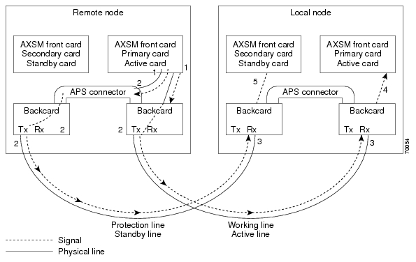
Managing Intercard APS Lines
In AXSM and AXSM/B intercard APS, either front card can be active, and can be connected to either APS line through the APS connector joining the two back cards. The following process describes how intercard APS communication works:
1.
2.
3.
4.
5.
6.
Note
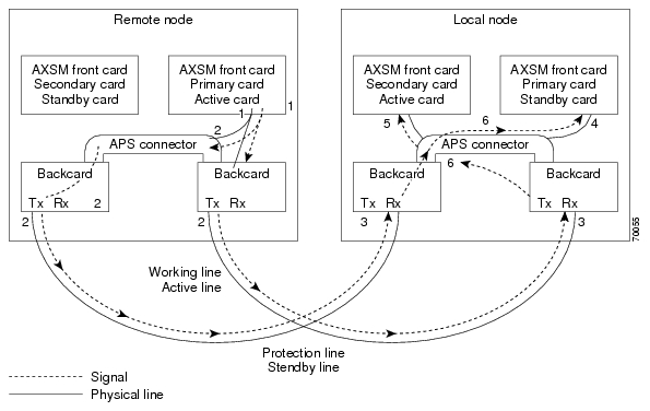
Figure 1 shows an example of how this process operates in a standard APS configuration, where the primary card monitors the working line and the secondary card monitors the protection line.
Figure 2 shows an example of how the APS communication process operates in a crossed APS configuration, where the secondary card monitors the working line that is attached to the primary card, and the primary card monitors the protection line that is connected to the secondary card.
Figure 1
Standard APS Configuration
Figure 2
Crossed APS Configuration
Line failures are always detected at the receive end of the line. This is where a switchover occurs when a failure is detected. Two different types of switchovers can occur, depending on whether the APS was configured as unidirectional or bidirectional in the cnfapsln command:
•
•
If the status of the standby line is good, a switchover from the failed active line to the standby is automatic.
Enter the cnfapsln command to enable an automatic switchover back to the working line after it recovers from a failure, as shown in the following example:
M8xx0_LA.1.AXSM.a > cnfapsln -w 1.1.1 -rv 2Table 1 describes the configurable parameters for the cnfapsln command.
If you want to manually switch from one line to another, enter the switchapsln <bay> <line> <switchOption> command, as shown in the following example:
M8xx0_LA.1.AXSM.a > switchapsln 1 1 6Manual line switch from protection to working succeeded on line 1.1.1Table 2 describes the configurable parameters for the cnfapsln command.
Enter the dspapslns command to verify that the active line switched over from the protection line to the working line, as shown in the following example:
M8xx0_LA.1.AXSM.a > dspapslnsWorking Prot. Conf Oper Active WLine PLine WTR Revt Conf Oper LastUserIndex Index Arch Arch Line State State (min) Dir Dir SwitchReq------- ----- ---- ----- ------ ----- ----- ----- ---- ---- ---- ----------1.1.1 2.1.1 1+1 1+1 working OK OK 5 Yes bi bi ManualP->WTroubleshooting APS Lines
Port light behavior changed in Release 3.0.00 as follows:
Port lights on AXSM /B front cards indicate the receive status of APS lines. The active front card always displays the status of the active line. The standby card always displays the status of the inactive line. If only one APS line fails, the line failure LED is always displayed on the standby front card.
Port lights on AXSMB front cards indicate the receive status of the Physical Line connected to it. For example, when APS is configured for working line as 5.1.3 and protection line as 6.1.3, regardless of which card is active, port LED on card 5 will show the receive status of 5.1.3 and card 6 will show the receive status of 6.1.3.
Note
Caution
If the active line fails and the standby line is not available, the switch reports a critical alarm.
If the active line fails and the standby line takes over, the former standby line becomes the new active line, and the switch reports a major alarm.
If an AXSM/A front card fails, APS communication between the redundant front cards fails. This can result in one of the following situations:
•
•
Use the following procedure to troubleshoot APS lines.
Step 1
M8xx0_LA.1.AXSM.a > dsplnsMedium MediumSonet Line Line Line Frame Line Line Alarm APSLine State Type Lpbk Scramble Coding Type State Enabled----- ----- ------------ ------ -------- ------ ------- ----- --------1.1 Up sonetSts12c NoLoop Enable Other ShortSMF Clear Enable1.2 Up sonetSts12c NoLoop Enable Other ShortSMF Clear Disable2.1 Up sonetSts12c NoLoop Enable Other ShortSMF Clear Disable2.2 Up sonetSts12c NoLoop Enable Other ShortSMF Clear DisableIf the line in alarm is an APS line, and has always functioned properly as an APS line, proceed to Step 2.
If the line in alarm has never functioned properly as an APS line, verify that the following are true:
•
•
•
Step 2
Note
Table 15 Troubleshooting APS Line Problems Using the dspaps Command
Working
OK
OK
Green
Green
Active card is receiving signal on working and protection lines. This does not guarantee that transmit lines are functioning properly. You must view the status on remote switch.
Protection
SF
OK
Green for
AXSM/A, Red for AXSM/A, Green for AXSM/BRed
Active card is receiving signal on the protection line. No signal received on the working line.
Working
OK
SF
Green
Red
Active card is receiving signal on the working line. No signal received on the protection line.
Working
SF
SF
Red
Red
Active card is not receiving signal from either line. The working line was the last line to work.
Protection
SF
SF
Red
Red
Active card is not receiving signal from either line. The protection line was the last line to work.
Working
UNAVAIL
UNAVAIL
The card set is not complete. One or more cards have failed or been removed. See Table 16 to troubleshoot card errors.
If one or both lines appear to be bad, determine whether the working or protection line is in alarm. Troubleshoot and correct the standby line first. Replace the components along the signal path until the problem is resolved.
•
•
•
Installing and Upgrading to Release 3.0.00
For upgrades, the term graceful means the process does not interrupt switch traffic or change the switch configuration.
Caution
The MGX 8850 (PXM1E) and MGX 8830 switches are introduced with release 3, and therefore cannot be upgraded to release 3.
The MGX 8850 (PXM45) switch can be gracefully upgraded to Release 3.0.00 from Releases 2.1.80. If the switch is running 2.0.16, it must be upgraded to 2.1.80, then Release 3.0.00.
Important Note
On a system running a pre-3.0.00 version of software, if there are AXSM/B (i.e., AXSM model B) cards in the shelf configured and running APS, we should check to see if the slots are reserved for AXSM/B or AXSM/A (check using dspcd command) before upgrading to 3.0.00 version of software. If they are reserved for model A, then there is no limitation. There is no limitation if APS is not configured either.
If they are reserved for AXSM/B and are running APS, then we would have a problem upon upgrade to 3.0.00 version with the card coming up with APS operational mode B, instead of the expected APS operational mode A. To overcome this problem, the steps in Single Card Scenario or Redundant Scenario need to be followed:
The workaround consists of basically reserving the AXSM card to Model A before upgrading the AXSM to 3.0.00. This workaround does not cause traffic loss.
Single card scenario
Step 1
Step 2
gShmFcResNvramIdSet <AXSM slot #>, <modelA NVid from Table 17>
It does not matter if the command is issued before upgrading the PXM or after. But the command should be issued before upgrading the AXSM. Table 17 shows how to map a given AXSM/B card with the corresponding AXSM/A NovramID.
Table 17 AXSM-B card mapping to corresponding AXSM-A NovramID
1port OC48-B
0x184
16port OC3-B
0x180
4port OC12-B
0x17E
Note
Redundant scenario
Issue the shellconn command for both the primary and secondary slot#.
Installation and Upgrade Procedures
The procedures in this section were extracted from two different manuals. The procedures appear in "Appendix A, Downloading and Installing Software Upgrades" in:
•
•
In this section, references to "chapters" refer to chapters in the above manuals.
Note
You can order manuals (see the "Ordering Documentation" section) or download them from the main Multiservice Switch Documentation site as follows:
Step 1
Step 2
•
•
•
Step 3
Step 4
Upgrade Process Overview
The following procedures are described in the remainder of this section:
•
•
•
•
•
•
Note
Caution
This section provides a series of quickstart procedures that describe how to perform graceful and non-graceful upgrades to the switch. To perform a graceful upgrade on a switch card, the card must be operating in redundant mode with another switch card of the same type. When performed properly, graceful upgrades have minimal impact on connections in progress and do not interrupt any established connections.
Note
When a card to be upgraded is not operating in redundant mode, you must do a non-graceful upgrade, which disrupts all traffic that passes through the card. For PXM45 cards, an ungraceful upgrade interrupts all traffic passing through the switch. For all other types of cards, an ungraceful upgrade affects only the traffic that passes through that card.
Each type of switch card runs boot and runtime software. The recommended sequence for upgrading the software (i.e., firmware) on switch cards is as follows:
1.
2.
3.
4.
Note
Typically, the boot software requires less frequent upgrades. However, in this release, both the boot and runtime software need to be upgraded.
When you upgrade the software on a switch card, proceed as follows:
•
•
•
The next subsection presents the quickstart procedures for switch card software upgrades.
Quickstart Procedures for Software Upgrades
The following subsections provide quickstart procedures for the following upgrades:
•
•
•
•
•
•
•
Caution
Preparing for Upgrades
Before you can upgrade the software on any card, you must copy the software to your switch and then log into the switch. The following table describes how to prepare for software upgrades on any card:
Graceful PXM45 Boot Upgrades
When performed properly, graceful upgrades have minimal impact on connections in progress and do not interrupt any established connections.
When a boot software upgrade is required, the procedure for upgrading redundant PXM45 cards updates the standby card and then makes that card active. This method ensures a smooth transition to the new software and preserves all established calls. Any calls that are not established are lost.
A graceful upgrade of the boot software does the following:
1.
2.
3.
Note
To upgrade the runtime software, use the following procedure.
Non-Graceful PXM45 Boot Upgrades
Ungraceful upgrades disrupt all switch traffic and are usually used in lab installations where the use of standalone cards provides no opportunity for a graceful upgrade. The quickstart procedure is provided as an overview and as a quick reference.
Note
Caution
Graceful PXM45 and AXSM Runtime Software Upgrades
When performed properly, graceful upgrades have minimal impact on connections in progress and do not interrupt any established connections.
This quickstart procedure applies to both PXM45 and AXSM cards and does the following:
1.
2.
3.
Note
Caution
Note
To upgrade the runtime software, use the following procedure.
Non-Graceful PXM45 and AXSM Runtime Software Upgrades
Ungraceful upgrades disrupt all switch traffic and are usually used in lab installations where the use of standalone cards provides no opportunity for a graceful upgrade. The quickstart procedure is provided as an overview and as a quick reference.
Note
Caution
Note
Graceful AXSM Boot Upgrades
When performed properly, graceful upgrades have minimal impact on connections in progress and do not interrupt any established connections. The quickstart procedure is provided as an overview and as a quick reference.
Note
Non-Graceful AXSM Boot Upgrades
Ungraceful upgrades disrupt all switch traffic and are usually used in lab installations where the use of standalone cards provides no opportunity for a graceful upgrade. The quickstart procedure is provided as an overview and as a quick reference.
Note
Browsing the File System
The active PXM45 hard disk stores log files, configuration files, and boot and runtime software. The switch operating system supports a set of UNIX-like commands that you can use to locate log files or manage software updates. Table 18 lists commands that you can use to browse the file system.
Note
Copying Software Files to the Switch
This section describes how to copy software files to the MGX 8850 switch. The switch cards use boot software and runtime software. Each PXM45 and AXSM card uses the boot software to define communications between the card components and to enable cards to start up. The runtime software defines how the card operates after startup.
Note
The MGX 8850 switches provide a File Transfer Protocol (FTP) service to support file transfers to the switch. If you have FTP client software and network connectivity to both the switch and the server where the software files are stored, you can use FTP to transfer files directly from the server to the switch.
Note
Step 1
Step 2
The procedure you use for transferring the files depends on the FTP client software you are using. When initiating the FTP connection, remember the following:
•
•
•
Step 3
Step 4
Note
Step 5
For more information on browsing the switch file system, see "Browsing the File System," which appears earlier in this section.
Upgrade Procedures for PXM45 and AXSM Cards
The following sections describe procedures that support upgrades to PXM45 and AXSM cards. For complete upgrade procedures, see "Quickstart Procedures for Software Upgrades," which appears earlier in this section. The procedures in this section detail some of the tasks listed in the quickstart procedures.
Upgrading PXM45 Boot Software
This section describes how to upgrade the PXM45 boot software on a single PXM45 card. If you are performing a graceful upgrade, use the quickstart procedure described in "Graceful PXM45 Boot Upgrades," which appears earlier in this section. The following procedure provides detailed information on the upgrade task within the quickstart procedure.
Step 1
Step 2
Step 3
pxm45bkup> sysFlashBootBurn "filename"Replace filename with the complete path to the boot file on the PXM45 hard drive. For example:
pxm45bkup> sysFlashBootBurn "C:FW/pxm45_003.000.000.000_bt.fw"Step 4
When the boot software burning process is complete, the switch displays a message similar to the following:
Flash download completed ...value = 0 = 0x0Step 5
pxm45bkup> rebootBe patient and wait for Login prompt to appear.
Step 6
M8xx0_NY.8.PXM.a >Step 7
M8xx0_NY.8.PXM.a > dsprevsM8xx0_NY System Rev: 03.00 Jun. 18, 2002 17:01:54 PSTMGX8850 Node Alarm: CRITICALPhysical Logical Inserted Cur Sw Boot FWSlot Slot Card Revision Revision-------- ------- -------- -------- --------01 01 AXSM_4OC12 3.0(0.0) 3.0(0.0)02 01 AXSM_4OC12 3.0(0.0) 3.0(0.0)03 03 AXSM_4OC12 3.0(0.0) 3.0(0.0)04 04 --- --- ---05 05 --- --- 3.0(0.0)06 06 --- --- 3.0(0.0)07 07 PXM45 3.0(0.0) 3.0(0.0)08 07 PXM45 3.0(0.0) 3.0(0.0)09 09 RPM_PR --- ---10 10 --- --- ---11 11 --- --- ---12 12 --- --- ---13 13 --- --- ---14 14 --- --- ---Step 8
The Boot FW Rev row in the display should show the new revision as shown in the following example:
8850_NY.7.PXM.a > dspcd8850_NY System Rev: 03.00 Jun. 18, 2002 22:47:23 PSTMGX8850 Node Alarm: NONESlot Number 7 Redundant Slot: 8Front Card Upper Card Lower Card---------- ---------- ----------Inserted Card: PXM45 UI Stratum3 PXM HardDiskDriveReserved Card: PXM45 UI Stratum3 PXM HardDiskDriveState: Active Active ActiveSerial Number: SBK050302AF SBK045203PJ SBK044602HJPrim SW Rev: 3.0(0) --- ---Sec SW Rev: 3.0(0) --- ---Cur SW Rev: 3.0(0) --- ---Boot FW Rev: 3.0(0) --- ---800-level Rev: A0 A0 A0800-level Part#: 800-06147-08 800-05787-02 800-05052-04CLEI Code: BAA670YCAA BA7IBCLAAA BA7IADNAAAReset Reason: On Power upCard Alarm: NONEFailed Reason: NoneMiscellaneous Information:Type <CR> to continue, Q<CR> to stop:After you confirm the upgrade to the first PXM45 card, the boot software upgrade for that card is complete.
Loading the Runtime Upgrade Software
This section describes how to load the runtime upgrade software in preparation for running it. Production switches should have redundant cards installed, so that upgrades can occur without interrupting traffic. For graceful upgrades, the upgrade software is loaded on the standby card first, and then the control is switched to upgraded card so that the other card can be upgraded.
The best way to assess the boot software upgrade status of a card is to enter the dsprevs command (without any parameters), as in the following example:
M8xx0_NY.8.PXM.a > dsprevsM8xx0_NY System Rev: 03.00 Jun. 18, 2002 17:14:58 PSTMGX8850 Node Alarm: CRITICALPhysical Logical Inserted Cur Sw Boot FWSlot Slot Card Revision Revision-------- ------- -------- -------- --------01 01 AXSM_4OC12 3.0(0.0) 3.0(0.0)02 01 AXSM_4OC12 3.0(0.0) 3.0(0.0)03 03 AXSM_4OC12 3.0(0.0) 3.0(0.0)04 04 --- --- ---05 05 --- --- 3.0(0.0)06 06 --- --- 3.0(0.0)07 07 PXM45 3.0(0.0) 3.0(0.0)08 07 PXM45 3.0(0.0) 3.0(0.0)09 09 RPM_PR --- ---10 10 --- --- ---11 11 --- --- ---12 12 --- --- ---13 13 --- --- ---14 14 --- --- ---The current (Cur SW Revision) software revision label indicates the status of an upgrade for runtime software. The boot (Boot FW Revision) label indicates the status of an upgrade for the boot software.To assess the runtime software upgrade status of a card, enter the dsprevs -s command. For example:
M8xx0_NY.8.PXM.a > dsprevs -sM8xx0_NY System Rev: 03.00 Jun. 18, 2002 17:10:49 PSTMGX8850 Node Alarm: CRITICALPhy. Log. Cur Sw Prim Sw Sec Sw Rev ChgSlot Slot Revision Revision Revision Status---- ---- -------- -------- -------- -------01 01 3.0(0.0) 3.0(0.0) 3.0(0.0) ---02 01 3.0(0.0) 3.0(0.0) 3.0(0.0) ---03 03 3.0(0.0) 3.0(0.0) 3.0(0.0) ---04 04 --- --- --- ---05 05 --- 3.0(0.0) 3.0(0.0) ---06 06 --- 3.0(0.0) 3.0(0.0) ---07 07 3.0(0.0) 3.0(0.0) 3.0(0.0) ---08 07 3.0(0.0) 3.0(0.0) 3.0(0.0) ---09 09 --- --- --- ---10 10 --- --- --- ---11 11 --- --- --- ---12 12 --- --- --- ---13 13 --- --- --- ---14 14 --- --- --- ---The current (Cur SW Revision), primary (Prim SW Revision), and secondary (Sec SW Revision) runtime software revision labels indicate the status of an upgrade for runtime software. In this example, these numbers match because the software upgrade has not started.
The primary software revision indicates which revision a card will run if it becomes active, and the secondary revision indicates an alternate revision that the card will use if the abortrev command is entered. (For more information on aborting an upgrade, see "Aborting a Runtime Software Upgrade," which appears later in this section.) The current software revision represents the software the active card is using. During a runtime upgrade, the Rev Change Status column shows when the revision command is in progress and subsequently when it is done.
The normal sequence of commands for a runtime software upgrade is loadrev, runrev, and commitrev. Table 19 shows how the software revision levels change during a graceful runtime software upgrade. Software Versions Reported During Graceful Upgrades
For non-graceful upgrades, the load process defines the software version to which the switch is about to be upgraded. Table 20 shows how the revision levels change during a non-graceful upgrade.
If you are performing a graceful upgrade, use the quickstart procedure described in "Graceful PXM45 and AXSM Runtime Software Upgrades," which appears earlier in this section. The following procedure provides detailed information on the load task within the quickstart procedure.
Step 1
mgx8850a.7.PXM.a > loadrev <slot> <revision>Replace <slot> with the card slot number for the card to be upgraded, and replace <revision> with the software version number for the update. For graceful upgrades, you can specify either the active or the standby card. The switch software will automatically load the upgrade runtime software on the standby card when it is installed. The following example shows how to enter this command:
mgx8850a.7.PXM.a > loadrev 7 3.0(0)After you enter the loadrev command, the standby card comes up in the standby-U state.
You can find the software version number in Table 3. You can also determine the version number from the runtime software filename as described in "Determining the Software Version Number from Filenames," which appears in Chapter 7, "Switch Operating Procedures."
Step 2
Step 3
M8xx0_NY.8.PXM.a > dsprevs -sM8xx0_NY System Rev: 03.00 Jun. 18, 2002 01:16:26 PSTMGX8850 Node Alarm: CRITICALPhy. Log. Cur Sw Prim Sw Sec Sw Rev ChgSlot Slot Revision Revision Revision Status---- ---- -------- -------- -------- -------01 01 3.0(0.0) 3.0(0.0) 3.0(0.0) ---02 01 3.0(0.0) 3.0(0.0) 3.0(0.0) ---03 03 3.0(0.0) 3.0(0.0) 3.0(0.0) ---04 04 --- --- --- ---05 05 --- 3.0(0.0) 3.0(0.0) ---06 06 --- 3.0(0.0) 3.0(0.0) ---07 07 3.0(0.0) 3.0(0.0) 3.0(0.0) ---08 07 3.0(0.0) 3.0(0.0) 3.0(0.0) ---09 09 --- --- --- ---10 10 --- --- --- ---11 11 --- --- --- ---12 12 --- --- --- ---13 13 --- --- --- ---14 14 --- --- --- ---
Note
Activating the Upgraded Runtime Software
After you load the upgraded runtime software for a PXM45 or AXSM card, enter the runrev command to start using the software. The version levels for graceful and non-graceful upgrades change as shown earlier in Table 19 and Table 20. The following procedure describes how to activate the upgraded runtime software.
Step 1
mgx8850a.7.PXM.a > runrev <slot> <revision>Replace <slot> with the card slot number, and replace <revision> with the software version number specified with the loadrev command. For graceful upgrades, you can specify either the active or the standby card. The switch software will automatically run the upgrade runtime software on the standby card when it is installed. The following example shows how to enter this command:
mgx8850a.7.PXM.a > runrev 7 3.0(0)The active card is reset, and the former standby card comes up in the active-U state.
Step 2
Step 3
M8xx0_NY.8.PXM.a > dsprevs -sM8xx0_NY System Rev: 03.00 Jun. 18, 2002 01:16:26 PSTMGX8850 Node Alarm: CRITICALPhy. Log. Cur Sw Prim Sw Sec Sw Rev ChgSlot Slot Revision Revision Revision Status---- ---- -------- -------- -------- -------01 01 3.0(0.0) 3.0(0.0) 3.0(0.0) ---02 01 3.0(0.0) 3.0(0.0) 3.0(0.0) ---03 03 3.0(0.0) 3.0(0.0) 3.0(0.0) ---04 04 --- --- --- ---05 05 --- 3.0(0.0) 3.0(0.0) ---06 06 --- 3.0(0.0) 3.0(0.0) ---07 07 3.0(0.0) 3.0(0.0) 3.0(0.0) ---08 07 3.0(0.0) 3.0(0.0) 3.0(0.0) ---09 09 --- --- --- ---10 10 --- --- --- ---11 11 --- --- --- ---12 12 --- --- --- ---13 13 --- --- --- ---14 14 --- --- --- ---Step 4
After the runrev command is entered, the switch starts running the new runtime software revision. The secondary software revision shows that a previous revision is still available. Whenever the secondary runtime software revision is different from the primary and current runtime software revisions, you can revert back to the secondary software revision as described in "Aborting a Runtime Software Upgrade," which appears later in this section.
Upgrading Boot Software on an AXSM Card
Note
The upgrade procedure for the boot software on a single AXSM card is the same for graceful and non-graceful upgrades. The difference between the graceful and non-graceful boot software upgrades is the sequence of commands before and after the upgrade on a single card. For information on the proper sequence see "Graceful AXSM Boot Upgrades" or "Non-Graceful AXSM Boot Upgrades," both of which appear earlier in this section.
To upgrade the boot software, use the following procedure.
Step 1
Step 2
Step 3
mgx8850a.7.PXM.a > burnboot <slot> <revision>Replace <slot> with the slot number of a standalone AXSM card or an AXSM card operating in standby mode. Replace <revision> with the software revision number to which you are upgrading. For example:
mgx8850a.7.PXM.a > burnboot 1 3.0(0)Step 4
After you confirm the upgrade, the new boot software is burned into the AXSM card and the card is reset. Be patient, the card reset takes some time. You can use the dsprevs command to display the status of the AXSM card. At first, the status may show that the card slot is empty or the card is rebooting. Reenter the command periodically to see the current status of the card. When the card status returns to active or standby, you are ready to continue.
M8xx0_NY.8.PXM.a > dsprevsM8xx0_NY System Rev: 03.00 Jun. 18, 2002 17:14:58 PSTMGX8850 Node Alarm: CRITICALPhysical Logical Inserted Cur Sw Boot FWSlot Slot Card Revision Revision-------- ------- -------- -------- --------01 01 AXSM_4OC12 3.0(0.0) 3.0(0.0)02 01 AXSM_4OC12 3.0(0.0) 3.0(0.0)03 03 AXSM_4OC12 3.0(0.0) 3.0(0.0)04 04 --- --- ---05 05 --- --- 3.0(0.0)06 06 --- --- 3.0(0.0)07 07 PXM45 3.0(0.0) 3.0(0.0)08 07 PXM45 3.0(0.0) 3.0(0.0)09 09 RPM_PR --- ---10 10 --- --- ---11 11 --- --- ---12 12 --- --- ---13 13 --- --- ---14 14 --- --- ---M8xx0_NY.8.PXM.a >Step 5
After you confirm the boot software upgrade to the AXSM card, the boot software upgrade for that card is complete.
Aborting a Runtime Software Upgrade
After upgrading PXM45 or AXSM runtime software, you can revert to the previously used version of software at any time, as long as you have not committed to the new software version with the commitrev command (which is described in the next section).
Note
To revert to the previously used runtime software version, use the following procedure.
Step 1
Step 2
M8xx0_NY.8.PXM.a > dsprevs -sM8xx0_NY System Rev: 03.00 Jun. 18, 2002 01:16:26 PSTMGX8850 Node Alarm: CRITICALPhy. Log. Cur Sw Prim Sw Sec Sw Rev ChgSlot Slot Revision Revision Revision Status---- ---- -------- -------- -------- -------01 01 3.0(0.0) 3.0(0.0) 3.0(0.0) ---02 01 3.0(0.0) 3.0(0.0) 3.0(0.0) ---03 03 3.0(0.0) 3.0(0.0) 3.0(0.0) ---04 04 --- --- --- ---05 05 --- 3.0(0.0) 3.0(0.0) ---06 06 --- 3.0(0.0) 3.0(0.0) ---07 07 3.0(0.0) 3.0(0.0) 3.0(0.0) ---08 07 3.0(0.0) 3.0(0.0) 3.0(0.0) ---09 09 --- --- --- ---10 10 --- --- --- ---11 11 --- --- --- ---12 12 --- --- --- ---13 13 --- --- --- ---14 14 --- --- --- ---To complete the next step, you need to know the secondary software revision shown in the display.
Note
Step 3
mgx8850a.7.PXM.a > abortrev <slot> <revision>Replace <slot> with the card slot number for the active PXM45 or AXSM card, and replace <revision> with the software version number for the secondary software revision.
Step 4
M8xx0_NY.8.PXM.a > dsprevs -sM8xx0_NY System Rev: 03.00 Jun. 18, 2002 01:16:26 PSTMGX8850 Node Alarm: CRITICALPhy. Log. Cur Sw Prim Sw Sec Sw Rev ChgSlot Slot Revision Revision Revision Status---- ---- -------- -------- -------- -------01 01 3.0(0.0) 3.0(0.0) 3.0(0.0) ---02 01 3.0(0.0) 3.0(0.0) 3.0(0.0) ---03 03 3.0(0.0) 3.0(0.0) 3.0(0.0) ---04 04 --- --- --- ---05 05 --- 3.0(0.0) 3.0(0.0) ---06 06 --- 3.0(0.0) 3.0(0.0) ---07 07 3.0(0.0) 3.0(0.0) 3.0(0.0) ---08 07 3.0(0.0) 3.0(0.0) 3.0(0.0) ---09 09 --- --- --- ---10 10 --- --- --- ---11 11 --- --- --- ---12 12 --- --- --- ---13 13 --- --- --- ---14 14 --- --- --- ---
Committing to a Runtime Software Upgrade
Committing to an upgrade does the following:
•
•
Once you are sure that an upgrade is stable, you can use the commitrev command to commit that software version. This prevents other administrators from inadvertently reverting to the previous version. You must also commit the current software version before you can upgrade to another software version or other additional cards.
Note
To commit the currently running runtime software version, use the following procedure:
Step 1
Step 2
a.
b.
M8xx0_NY.8.PXM.a > dsprevs -sM8xx0_NY System Rev: 03.00 Jun. 18, 2002 01:16:26 PSTMGX8850 Node Alarm: CRITICALPhy. Log. Cur Sw Prim Sw Sec Sw Rev ChgSlot Slot Revision Revision Revision Status---- ---- -------- -------- -------- -------01 01 3.0(0.0) 3.0(0.0) 3.0(0.0) ---02 01 3.0(0.0) 3.0(0.0) 3.0(0.0) ---03 03 3.0(0.0) 3.0(0.0) 3.0(0.0) ---04 04 --- --- --- ---05 05 --- 3.0(0.0) 3.0(0.0) ---06 06 --- 3.0(0.0) 3.0(0.0) ---07 07 3.0(0.0) 3.0(0.0) 3.0(0.0) ---08 07 3.0(0.0) 3.0(0.0) 3.0(0.0) ---09 09 --- --- --- ---10 10 --- --- --- ---11 11 --- --- --- ---12 12 --- --- --- ---13 13 --- --- --- ---14 14 --- --- --- ---c.
If all version numbers are identical, the runtime software can be upgraded. There is no need to commit to the current software revision.
Step 3
mgx8850a.7.PXM.a > commitrev <slot> <revision>Replace <slot> with the card slot number for the active PXM45 or AXSM card, and replace <revision> with the software version number for the currently used software version. To display the software version numbers, use the dsprevs -s command to view the software version in use.
M8xx0_NY.8.PXM.a > dsprevs -sM8xx0_NY System Rev: 03.00 Jun. 18, 2002 01:16:26 PSTMGX8850 Node Alarm: CRITICALPhy. Log. Cur Sw Prim Sw Sec Sw Rev ChgSlot Slot Revision Revision Revision Status---- ---- -------- -------- -------- -------01 01 3.0(0.0) 3.0(0.0) 3.0(0.0) ---02 01 3.0(0.0) 3.0(0.0) 3.0(0.0) ---03 03 3.0(0.0) 3.0(0.0) 3.0(0.0) ---04 04 --- --- --- ---05 05 --- 3.0(0.0) 3.0(0.0) ---06 06 --- 3.0(0.0) 3.0(0.0) ---07 07 3.0(0.0) 3.0(0.0) 3.0(0.0) ---08 07 3.0(0.0) 3.0(0.0) 3.0(0.0) ---09 09 --- --- --- ---10 10 --- --- --- ---11 11 --- --- --- ---12 12 --- --- --- ---13 13 --- --- --- ---14 14 --- --- --- ---
Note
Troubleshooting Upgrade Problems
Table 21 lists symptoms of upgrade problems and suggestions on how to correct them.
Tips
Documentation
Release notes ship with the switch. You can also download the release notes and other documentation from http://www.cisco.com/univercd/cc/td/doc/product/wanbu/index.htm, or you can order printed manuals (see "Ordering Documentation").
Note
Related Documentation
The following Cisco publications contain additional information related to the operation of this product and associated equipment in a Cisco WAN switching network.
Cisco WAN Manager Release 11.0.00
The product documentation for the Cisco WAN Manager (CWM) network management system for Release 11.0.00 is listed in Table 22.
Cisco MGX 8850 (PXM45) Multiservice Switch Release 3
The product documentation for the installation and operation of the MGX 8850 Multiservice Switch for Release 3 is listed in Table 23.
Table 23 Cisco MGX 8850 (PXM45) Multiservice Switch Release 3 Documentation
Cisco MGX 8850 Hardware Installation Guide, Release 3 (PXM45/B and PXM1E)
DOC-7814250=
Describes how to install the MGX 8850 multiservice switch. This guide explains what the switch does and covers site preparation, grounding, safety, card installation, and cabling. The MGX 8850 switch uses either a PXM45 or a PXM1E controller card and provides support for both broadband and narrow band service modules.
Cisco MGX 8850, MGX 8950, and MGX 8830 Command Reference (PXM45/B and PXM1E), Release 3
DOC-7814245=
Describes how to use the PXM and AXSM commands that are available for the MGX 8850, MGX 8950, and MGX 8830 switches.
Cisco Frame Relay Software Configuration Guide and Command Reference for the MGX 8850 FRSM12 Card, Release 3
DOC-7810327=
Describes how to use the high-speed Frame Relay (FRSM12) commands that are available for the MGX 8850 switch.
Cisco MGX 8850 (PXM45) and MGX 8950 Software Configuration Guide, Release 3
DOC-7814577=
Describes how to configure MGX 8850 and MGX 8950 switches with PXM45 controller cards to operate as ATM edge or core switches. This guide also provides some operation and maintenance procedures.
Cisco MGX and SES PNNI Network Planning Guide for MGX Release 3 and SES Release 3
DOC-7814261=
Provides guidelines for planning a PNNI network that uses the MGX 8850 and the MGX 8950 switches and the BPX 8600 switches. When connected to a PNNI network, each BPX 8600 series switch requires a SES for PNNI route processing.
OL-2521-01 (online only)
Describes how to install and configure VISM1 in several MGX 8000 Series switches. This guide is available online only.
Cisco MGX Route Processor Module (RPM-XF) Installation and Configuration Guide, Release 3
OL-2768-01 (online only)
Describes how to install and configure the MGX Route Processor Module (RPM-XF) in the MGX 8850 Release 3 switch. Also provides site preparation, troubleshooting, maintenance, cable and connector specifications, and basic Cisco IOS configuration information.
Cisco MGX Route Processor Module (RPM-PR) Installation and Configuration Guide, Release 2.1
DOC-7812510=
Describes how to install and configure the MGX Route Processor Module (RPM-PR) in the MGX 8850 Release 2.1 and later switches. Also provides site preparation, troubleshooting, maintenance, cable and connector specifications, and basic Cisco IOS configuration information.
Release Notes for Cisco MGX Route Processor Module (RPM/B and RPM-PR) for Release 1.2.10 and Release 3
78-14243-01
Provides the latest feature, upgrade, and compatibility information, as well as known and resolved anomalies for RPM-PR.
1 VISM = Voice Interworking Service Module
Cisco MGX 8850 (PXM1E) Multiservice Switch Release 3
The product documentation for the installation and operation of the Cisco MGX 8850 (PXM1E) Multiservice Switch Release 3 is listed in Table 24.
Cisco MGX 8950 Multiservice Switch Release 3
The product documentation for the installation and operation of the MGX 8950 Multiservice Switch for Release 3.0.00 is listed in Table 25.
Service Expansion Shelf PNNI Controller Release 3
The product documentation for the installation and operation of the Service Expansion Shelf (SES) PNNI Controller is listed in Table 26.
Cisco MGX 8830 Multiservice Switch Release 3
The product documentation for the installation and operation of the MGX 8830 Multiservice Switch Release 3.0.00 is listed in Table 27.
Cisco WAN Switching Software Release 9.3.40
The product documentation for the installation and operation of the Cisco WAN Switching Software Release 9.3.40 is listed in Table 28.
MGX 8850 (PXM1) Multiservice Switch Release 1.2.10
The product documentation for the installation and operation of the MGX 8850 (PXM1) Multiservice Switch is listed in Table 29.
MGX 8250 Edge Concentrator Release 1.2.10
The documentation for the installation and operation of the MGX 8250 Edge Concentrator is listed in Table 30.
MGX 8230 Edge Concentrator Release 1.2.10
The documentation for the installation and operation of the MGX 8230 Edge Concentrator is listed in Table 31.
Ordering Documentation
Cisco documentation is available in the following ways:
•
http://www.cisco.com/public/ordsum.html
Starting with MGX 2.1.60 and its associated releases, printed documentation is offered through the "Printed Information Ordering" site, which can be accessed through:
http://www.cisco.com/univercd/cc/td/doc/es_inpck/pdi.htm
•
http://www.cisco.com/go/subscription
•
Documentation on the World Wide Web
You can access the most current Cisco documentation on the World Wide Web at the following sites:
•
•
•
Documentation CD-ROM
Cisco documentation and additional literature are available in a CD-ROM package, which ships with your product. The Documentation CD-ROM is updated monthly and may be more current than printed documentation. The CD-ROM package is available as a single unit or as an annual subscription as mentioned above.
Documentation Feedback
If you are reading Cisco product documentation on the World Wide Web, you can submit technical comments electronically. Click Feedback in the toolbar and select Documentation. After you complete the form, click Submit to send it to Cisco.
You can e-mail your comments to bug-doc@cisco.com or msspubs-feedback@cisco.com.
To submit your comments by mail, use the response card behind the front cover of your document, or write to the following address:
Attn: Document Resource Connection
Cisco Systems, Inc.
170 West Tasman Drive
San Jose, CA 95134-9883We appreciate your comments.
Technical Assistance
Cisco provides Cisco.com as a starting point for all technical assistance. Customers and partners can obtain documentation, troubleshooting tips, and sample configurations from online tools. For Cisco.com registered users, additional troubleshooting tools are available from the TAC website.
Cisco.com
Cisco.com is the foundation of a suite of interactive, networked services that provides immediate, open access to Cisco information and resources at anytime, from anywhere in the world. This highly integrated Internet application is a powerful, easy-to-use tool for doing business with Cisco.
Cisco.com provides a broad range of features and services to help customers and partners streamline business processes and improve productivity. Through Cisco.com, you can find information about Cisco and our networking solutions, services, and programs. In addition, you can resolve technical issues with online technical support, download and test software packages, and order Cisco learning materials and merchandise. Valuable online skill assessment, training, and certification programs are also available.
Customers and partners can self-register on Cisco.com to obtain additional personalized information and services. Registered users can order products, check on the status of an order, access technical support, and view benefits specific to their relationships with Cisco.
To access Cisco.com, go to http://www.cisco.com
Technical Assistance Center
The Cisco TAC website is available to all customers who need technical assistance with a Cisco product or technology that is under warranty or covered by a maintenance contract.
Contacting TAC by Using the Cisco TAC Website
If you have a priority level 3 (P3) or priority level 4 (P4) problem, contact TAC by going to the TAC website:
http://www.cisco.com/tac
P3 and P4 level problems are defined as follows:
•
•
In each of the above cases, use the Cisco TAC website to quickly find answers to your questions.
Note
If you cannot resolve your technical issue by using the TAC online resources, Cisco.com registered users can open a case online by using the TAC Case Open tool at http://www.cisco.com/tac/caseopen
Contacting TAC by Telephone
If you have a priority level 1(P1) or priority level 2 (P2) problem, contact TAC by telephone and immediately open a case. To obtain a directory of toll-free numbers for your country, go to the following website:
http://www.cisco.com/warp/public/687/Directory/DirTAC.shtml
P1 and P2 level problems are defined as follows:
•
•
Caveats
This section provides information about known anomalies.
MGX 8830 Anomalies
Table 32lists the anomalies and known workarounds for release 3.
MGX 8850 Anomalies
Severity level 1 and 2 anomalies are organized as follows:
•
•
Known Anomalies in Release 3.0.00
Table 33 lists the anomalies and known workarounds for release 3.
Anomalies Resolved in Release 3.0.00
Table 34 lists the anomalies resolved in Release 3.0.00. Specifically, these are anomalies opened against version 2.0 or 2.1 images and fixed in 3.0--but not fixed in 2.0 or 2.1.
Known Route Processor Module or MPLS Anomalies
For information about anomalies with the RPM-PR or RPM/B card, refer to "Release Notes for Cisco MGX Route Processor Module (RPM/B and RPM-PR) for MGX Release 1.2.10 and MGX Release 3."
For information about anomalies with the RPM-XF card, refer to "Release Notes for Cisco MGX Route Processor Module (RPM-XF) for MGX 8850 Release 3.0.00 (PXM45)."
MGX-RPM-XF-512 Anomalies
The new MGX-RPM-XF-512 card supports MGX 8850 (PXM45), Release 3.0.00.
For information about anomalies with the MGX-RPM-XF-512 card, refer to "Release Notes for Cisco MGX Route Processor Module (RPM-XF) for Release 3.0.00 of MGX 8850 (PXM45)".
Acronyms
Table 36 lists acronyms used in these release notes.
This document is to be used in conjunction with the documents listed in the "Related Documentation" section.
AccessPath, AtmDirector, Browse with Me, CCDA, CCDE, CCDP, CCIE, CCNA, CCNP, CCSI, CD-PAC, CiscoLink, the Cisco NetWorks logo, the Cisco Powered Network logo, Cisco Systems Networking Academy, the Cisco Systems Networking Academy logo, Fast Step, Follow Me Browsing, FormShare, FrameShare, GigaStack, IGX, Internet Quotient, IP/VC, iQ Breakthrough, iQ Expertise, iQ FastTrack, the iQ Logo, iQ Net Readiness Scorecard, MGX, the Networkers logo, Packet, RateMUX, ScriptBuilder, ScriptShare, SlideCast, SMARTnet, TransPath, Unity, Voice LAN, Wavelength Router, and WebViewer are trademarks of Cisco Systems, Inc.; Changing the Way We Work, Live, Play, and Learn, Discover All That's Possible, and Empowering the Internet Generation, are service marks of Cisco Systems, Inc.; and Aironet, ASIST, BPX, Catalyst, Cisco, the Cisco Certified Internetwork Expert logo, Cisco IOS, the Cisco IOS logo, Cisco Systems, Cisco Systems Capital, the Cisco Systems logo, Enterprise/Solver, EtherChannel, EtherSwitch, FastHub, FastSwitch, IOS, IP/TV, LightStream, MICA, Network Registrar, PIX, Post-Routing, Pre-Routing, Registrar, StrataView Plus, Stratm, SwitchProbe, TeleRouter, and VCO are registered trademarks of Cisco Systems, Inc. and/or its affiliates in the U.S. and certain other countries.
All other brands, names, or trademarks mentioned in this document or Web site are the property of their respective owners. The use of the word partner does not imply a partnership relationship between Cisco and any other company. (0104R)
Copyright © 2002, Cisco Systems, Inc.
All rights reserved.