[an error occurred while processing this directive]

Cisco MGX 8900 Series Switches

2.1.79 Release Notes for MGX 8950

 Feedback

Table Of Contents

Release Notes for Cisco MGX 8950 Software Version 2.1.79

Contents

About Release 2.1.79

Type of Release

About the New MGX 8950 Switch

Description

The XM-60 Switch Fabric Card

Software Information

Benefits

Platforms/Considerations

Design Guides and Application Notes

References

Limitations

Marketing Contact

Locating Software Updates

Acronyms

System Requirements

Software/Firmware Compatibility Matrix

Additional Compatibility Information

Hardware Supported

Hardware Compatibility Matrix

New and Changed Information

New Features and Enhancements in Release 2.1.60 through 2.1.79

MGX/BPX APS Interoperability

Hierarchical PNNI (Multiple Peer Group [MPG])

192 Interfaces on PXM45/B

UNI 4.0

AINI

LDP on RPM-PR

Multi-LVC on RPM

RPM 1:N Redundancy

switchredcd Command on RPM-PR

New Features in Release 2.1.70

Config Verify

New Features in Release 2.1.79

Multiprotocol Label Switching (MPLS) over ATM using VC Merge

Enhancements

Additional Software Information

MIB

Service Class Template File Information

New Hardware Supported in Release 2.1.76

AXSM-1-2488/B (No APS support)

New and Changed Commands

New Commands

New Commands for the MGX 8850 Switch Only

Changed CLI Commands

Removed Commands

Previously Undocumented Commands

Limitations and Restrictions

General Limitations, Restrictions, and Notes

Limitations for rteopt via parallel links

Important Notes

RPM-PR and MPLS Limitations, Restrictions, and Notes

RPM-PR and MPLS Notes

Booting the RPM-PR

RPM-PR Bootflash Precautions

APS Management Information

Preparing for Intercard APS

Managing Intercard APS Lines

Troubleshooting APS Lines

Clearing the Configuration on Redundant PXM45 Cards

Recommendations

Installing and Upgrading to Release 2.1.79

Upgrade Process Overview

Quickstart Procedures for Software Upgrades

Browsing the File System

Copying Software Files to the Switch

Upgrade Procedures for PXM45 and AXSM Cards

Upgrade Procedures for RPM-PR Cards

Using XModem to Download Flash to RPM Cards

Troubleshooting Upgrade Problems

Documentation

Related Documentation

Cisco WAN Manager Release 10.5 Documentation

Cisco MGX 8850 Release 2.1 Documentation

Cisco MGX 8950 Release 2.1 Documentation

SES PNNI Release 1.1 Documentation

Cisco WAN Switching Software, Release 9.3 Documentation

MGX 8850 Multiservice Switch, Release 1.1.40 Documentation

MGX 8250 Edge Concentrator, Release 1.1.40 Documentation

MGX 8230 Multiservice Gateway, Release 1.1.40 Documentation

Ordering Documentation

Documentation on the World Wide Web

Documentation CD-ROM

Documentation Feedback

Technical Assistance

Cisco.com

Technical Assistance Center

Contacting TAC by Using the Cisco TAC Website

Contacting TAC by Telephone

Caveats

Known Anomalies in Release 2.1.79

Anomalies Resolved in Release 2.1.79

Anomalies Known in Release 2.1.76

Known RPM-PR/MPLS Anomalies


Release Notes for Cisco MGX 8950 Software Version 2.1.79


Contents

About Release 2.1.79

These release notes describe the system requirements, new features, and limitations that apply to Release 2.1.79 for the MGX 8950 multi-service switch. These notes also contain Cisco support information.

Use this document in conjunction with the documents listed in the "Related Documentation" section.

Type of Release

Release 2.1.79 is a maintenance release for the MGX 8850 switch and a hardware and software release for the new MGX 8950 switch.

For information about the MGX 8850, see the "Release Notes for Cisco MGX 8850 Software Version 2.1.79."

About the New MGX 8950 Switch

Description

The MGX 8950 Multiservice Switch was introduced with software release 2.1.76. For your convenience, information from that release is repeated here.

The MGX 8950 switch extends the MGX family to provide backbone switching solutions for major service provider networks.

In its first release, the MGX 8950 leverages the AXSM/B card set currently available on the MGX 8850 for the service modules and the PXM-45/B for the control processor. MGX Release 2.1.76 is the first MGX software to support the MGX 8950 platform.

The MGX 8950 differs from the MGX 8850 in two major areas:

The MGX 8950 switch has no future narrowband support capability planned.

The MGX 8950 introduces a new switching fabric card, the XM-60.

The majority of features developed in earlier releases of the MGX 8850 switch also apply to the new MGX 8950 switch. Please call Product Management for confirmation of a particular feature.

The XM-60 Switch Fabric Card

In order to increase the switching capacity of the MGX 8950 product, a new switch fabric card was developed, called the XM-60. MGX 8950 can accommodate up to four XM-60 cards, each of which provides up to 60 Gbps of raw switching capacity. MGX 8950 does not use the 45 Gbps switch on the PXM like the MGX 8850, the PXM45/Bs are used as processors and management interfaces. This physically separates the user traffic from the control traffic, an architecture designed for the highest availability. In later releases, an MGX 8950 populated with 4 XM-60 switching fabrics and OC192c/STM64 cards will allow a full-duplex 10 Gbps line rate to each slot (even if one of the XM-60s were to fail). In the first release (2.1.76), the AXSM/B cards will use the XM-60s to achieve full line rate OC48c/STM-1, just as in the MGX 8850.

Software Information

The MGX 8950 uses the same software as the MGX 8850. The initial release of software that supports MGX 8950 is Release 2.1.76. This release also supports MPLS functionality. A later release will add higher speed line cards to fully use the capacity of the XM-60s and the serial lines on the backplane.

PNNI Information

The MGX 8950 uses the same PNNI code base as the MGX 8850, and runs it on the same processor--the PXM45/B. Complete interoperability is tested, and many if not all PNNI features that are supported on the MGX 8850 are supported on MGX 8950.

MPLS Information

MPLS functionality is supported in Release 2.1.76 by using a Route Processor Module (RPM-PR). Please note that since MGX 8950 is intended to be primarily a core platform with the current release, the RPM-PR acts only as the label switch controller for the platform. Even though the RPM-PR is the same one that is supported on the MGX 8850, edge functionality is not provided on the MGX 8950 with Release 2.1.76.

CWM Information

Basic connection provisioning on MGX 8950 is supported by CWM 10.5.10.

Benefits

Network applications that will benefit from the MGX 8950 include the following:

Pure ATM scaling to OC-192c, with PNNI used throughout as the control plane

High-end ATM-based multiservice aggregation, serving as a gateway to an IP/MPLS core. A PNNI control plane is used at the edge, and an MPLS control plane in the core. This migration can take place in stages.

Non-IP multiservice traffic is maintained across an ATM core, and IP traffic is offloaded to a separate IP network.

Platforms/Considerations

The MGX 8950 is the high-end platform in the MGX family.

Design Guides and Application Notes

None available. See the "Related Documentation" list for additional customer documentation.

References

None available.

Limitations

Only AXSM/B cards are s2upported. AXSM and AXSM-E cards are not supported on the MGX 8950 and will fail if installed in the system.

Only PXM45/B control processors are supported. The earlier PXM45 version processor is not supported on MGX 8950, and will fail if installed in the system

Marketing Contact

Contact Hugues Metayer or David Pool in the Multiservice Switching Business Unit of Cisco.

Locating Software Updates

Software updates are located at Cisco Connection Online (CCO) at http://www.cisco.com/kobayashi/sw-center/beta

Acronyms

Table 1 lists acronyms used in these release notes.

Table 1 Acronyms and Their Descriptions  

Acronym
Description

AINI

ATM Inter-Network Interface

APS

automatic protection switching

ATM

asynchronous transmission mode

AXSM

ATM Switch Service Module

B-ISUP

Broadband ISDN User Part

BPX

an earlier Cisco backbone switch

CLI

command line interface

CWM

Cisco Wide Area Network Manager

DSLAM

digital subscriber line access module

IETF

Internet Engineering Task Force

LDP

label distribution protocol

LSC

label switch controller

LSP

label switched paths

LSR

label switch router

MIB

management information base

MPG

multiple peer group

MPLS

multiple protocol label switching

NCDP

network clock distribution protocol

PGL

peer group leader

PNNI

private network-to-network interface

PXM

processor switch module

RCC

routing control channel

RPM

route processor module

RPM-PR

route processor module - Premium

SCT

service class template

SLA

service level agreement

SM

service module (a card)

SNMP

simple network management protocol

SPVC

soft permanent virtual connection

SVC

switched virtual circuit

UNI

User-Network Interface

VCI

virtual channel identifier

VPI

virtual path identifier


System Requirements

This section describes software compatible with this release, and lists the hardware supported in this release.

Software/Firmware Compatibility Matrix

Table 2 lists Cisco WAN or IOS products that are interoperable with MGX Release 2.1.79.

Table 2 WAN and IOS Software Version Compatibility Matrix 

Cisco WAN or IOS Products
Current Release
One release before current release
Two releases before current release

CWM

10.5.10 P2

n/a

n/a

MGX 1

1.2.01

1.1.41

n/a

MGX 2

2.1.79

2.1.76

n/a

BPG/IGX

9.3.36

n/a

n/a

MGX 8220

5.0.18

4.1.12

n/a

SES

1.1.75

1.0.16

n/a

Firmware

latest for all

latest for all

latest

IOS

12.2(8)T4

12.2(8)T2

n/a

VISM

2.2

2.1

n/a


Table 3 lists the software that is compatible for use in a switch running Release 2.1.79 software. Note that the AXSM/B cards use the same software as AXSM cards.

Table 3 MGX and RPM Software Version Compatibility Matrix

Board Pair
Boot Software
Minimum
Boot Code
Version
Runtime Software
Latest
Firmware
Version
Minimum
Firmware
Version

PXM45/B

pxm45_002.001.079.101_bt.fw

2.1.79

pxm45_002.001.079.101_mgx.fw

2.1.79

2.1.79

AXSM-1-2488/B

axsm_002.001.079.101_bt.fw

2.1.79

axsm_002.001.079.101.fw

2.1.79

2.1.79

AXSM-16-155/B

AXSM-4-622/B

AXSM-16-T3/E3/B

RPM-PR

rpm-boot-mz.122-8.T4

12.2(8)T4

rpm-js-mz.122-8.T4

12.2(8)T4

12.2(8)T4


Additional Compatibility Information

The following notes provide additional compatibility information for this release:

You can gracefully upgrade to Release 2.1.79 from Release 2.1.76.

MGX 2.1.79 interoperates with SES PNNI 1.175 plus BPX Switch Software (SWSW) 9.3.30 plus BXM MFN.

This release supports feeder connections from Cisco MGX 8850 Release 1.1.41 and 1.2.01. Please see the "Release Notes for MGX 8850, 8230, and 8250 Software Version 1.1.40" for feeder feature issues. Release notes can be downloaded from http://www.cisco.com/univercd/cc/td/doc/product/wanbu/index.htm.

You must use CWM Release 10.5.10 (2) to manage networks that contain MGX switches running Release 2.1.76.

The RPM-PR software in this release is based on IOS Release 12.2(8)T4.

The SNMP MIB release for 2.1.79 is mgxmibs2176.tar

Hardware Supported

Table 4 lists the hardware supported in Release 2.1.79. Note that the MGX 8950 does not support the AXSM/A or the new AXSM-E cards. If these cards are present, they will show up as "Failed" when the dspcds command is issued.

Table 4 Hardware Supported in Release 2.1.79for MGX 8950  

Product ID
800 Part Number
Minimum Revision

PXM45/B

800-09266-04

-A0

PXM-UI-S3

800-05787-02

-A0

PXM-HD

800-05052-03

-A0

AXSM-1-2488/B

800-07983-02

-A0

SMFSR-1-2488/B

800-07255-01

-A0

SMFLR-1-2488/B

800-08847-01

-A0

SMFXLR-1-2488/B

800-08849-01

-A0

AXSM-16-155/B

800-07909-05

-A0

AXSM-4-622/B

800-07910-05

-A0

AXSM-16-T3E3/B

800-07911-05

-A0

MMF-8-155-MT/B

800-07120-02

-A0

SMFIR-8-155-LC/B

800-07864-02

-B0

SMFLR-8-155-LC/B

800-07865-02

-B0

SMFIR-2-622/B

800-07412-02

-B0

SMFLR-2-622/B

800-07413-02

-B0

SMB-8-T3

800-05029-02

-A0

SMB-8-E3

800-04093-02

-A0

SMB-4-155

800-07425-02

-A0

XM-60

800-04706-06

-A0

MGX-APS-CON-8950

800-15308-01

-A0

RPM-PR-256

800-07178-02

-A0

RPM-PR-512

800-07656-02

-A0

MGX-MMF-FE

800-03202-02

-A0

MGX-RJ45-4E/B

800-12134-01

-A0

MGX-RJ45-FE

800-02735-02

-A0


Hardware Compatibility Matrix

Table 5 shows which back cards can be used with each front card in Release 2.1.79 .

Table 5 Back Cards and Connectors Supported by Front Cards 

Front Card Type
Back Card Types
Supports APS Connector (MGX-APS-CON)

AXSM-1-2488/B

SMFSR-1-2488/B
SMFLR-1-2488/B
SMFXLR-1-2488/B

Yes
Yes
Yes

AXSM-4-622/B

SMFIR-2-622/B
SMFLR-2-622/B

Yes
Yes

AXSM-16-155/B

SMB-4-155
MMF-8-155-MT/B
SMFIR-8-155-LC/B
SMFLR-8-155-LC/B

Yes
Yes
Yes
Yes

AXSM-16-T3E3/B

SMB-8-T3
SMB-8-E3

N/A

PXM45/B

PXM-HD
PXM-UI-S3

N/A

RPM-PR-256
RPM-PR-512

MGX-MMF-FE
MGX-RJ45-4E/B
MGX-RJ45-FE

N/A


New and Changed Information

This section contains a summary of recent features, hardware, or commands that have been implemented in MGX 8850.

New Features and Enhancements in Release 2.1.60 through 2.1.79

Release 2.1.60 contained these new features:

MGX/BPX automatic protection switching (APS) Interoperability

Hierarchical PNNI (Multiple Peer Group [MPG])

192 Interfaces on PXM45/B

UNI 4.0

ATM Inter-Network Interface (AINI)

LDP on RPM-PR

Multi-LVC on RPM

RPM 1:N Redundancy on MGX 8950

switchredcd command for RPM

MGX/BPX APS Interoperability

This feature verifies that the Automatic Protection Switching (APS) feature operates as described in the Telcordia GR-253 standard on both the MGX and the BPX switches.

Benefits

Cisco's multiservice customers, whose networks started out with the BPX as a backbone switch, have APS operation unchanged as their networks evolve to include the MGX 8850 and 8950 switch.

Hierarchical PNNI (Multiple Peer Group [MPG])

Hierarchical PNNI (also referred to as Multiple Peer Group PNNI) allows the growth of PNNI networks to a very large size. As a simple example, a network with two levels of hierarchy and 50 nodes in each peer group and 50 groups would have 2500 nodes. Another way to describe this is as 50 peer groups, each containing 50 nodes. Expanding the same design to 3 levels of hierarchy yields 125,000 nodes. While network topology constraints will usually limit the size to smaller numbers, the growth potential is clear.

The practical size of PNNI networks is limited by several factors, all of which use either processor real time, or memory on the node:

Number of nodes in a peer group.

Number of "visible" nodes. This is the number of nodes seen by a node that connects to other peer groups. This number includes the number of nodes in the local peer group, as well as all other peer groups that can be seen from a particular node's view into the hierarchical network.

The number of PNNI links in a peer group.

The number of registered ATM addresses in a network.

The number of connections supported on the local node.

The average number of 10 links per node and 2000 addresses per node with average of 2 summary addresses per node.

For complete details, refer to the "Cisco MGX and SES PNNI Network Planning Guide" (see "Related Documentation" later in these notes).

The software can support up to 10 hierarchical levels. Testing of 2.1.79 is performed for four hierarchical levels.

To prepare for the future addition of hierarchy to a PNNI network, the addressing scheme should be planned prior to the provisioning of any connections on a PNNI network. If, at any time in the future, hierarchy must be added to a network in which the addressing was not planned properly, connections will have to be re-provisioned using the new addressing scheme.

Benefits

The introduction of hierarchical PNNI enables the building of very large ATM networks. It also enables the growth of flat PNNI networks with the addition of hierarchy. Enabling hierarchy on an existing PNNI network has no impact on existing ATM connections, assuming that the addressing scheme was planned in advance to accommodate hierarchy. Since connections can be managed end-to-end across a hierarchical network, the manageability of networks can be increased in situations that previously required splitting a large network into multiple routing domains.

192 Interfaces on PXM45/B

The PXM45/B module supports up to 192 interfaces. A physical port/trunk, virtual trunk or a logical port is counted as an interface. Among 192 interfaces, up to 100 interfaces can be signaling ports. The other 92 interfaces should be non-signaling ports, such as non self-supporting ports.

Benefits

Support for 192 interfaces allows the ability to completely fill the chassis (12 slots) with broadband service module ports, e.g., AXSM-16-155/B.

UNI 4.0

MGX 8850 switches currently provide UNI signaling compliant with ATM Forum UNI 3.1 (af-uni-0010.002). This feature adds the ability to utilize the UNI 4.0 protocol when connecting to ATM UNI devices that require signaling support. Also included in this feature is support for the ITU signaling specification Q.2931.

Benefits

The UNI 4.0 signaling capability is required to provide complete and standard interoperability with UNI devices in common use. Applications enabled by the full implementation of UNI 4.0 include voice transport, connection to certain class 5 voice switching equipment, and enhanced SVC UNI services including ABR.

AINI

The ATM Inter-Network Interface (AINI) is the new inter-networking standard for PNNI to PNNI, PNNI to B-ISUP, and B-ISUP to B-ISUP internetworking. AINI provides most of the advantages of PNNI networking and allows for a secure interface that does not allow the exchange of network topology and availability information.

AINI provides a resilient interface between networks since it takes advantage of many aspects of PNNI. Despite using static routes, AINI offers crankback, alternate routes, and load balancing across multiple parallel links. Crankback is defined as a mechanism for partially releasing a connection setup in progress, which has encountered a failure. This mechanism allows PNNI to perform alternate routing.

AINI support includes:

UNI 4.0 based signalling

Supports UNI 4.0 call types including ABR

Crankback on AINI links used for Alternate routing

Load balancing across multiple AINI links

Path and Connection Trace across AINI links

Support for Hop Counter Information Element to detect loops

Configurable VPI/VCI allocator Node (between AINI peer nodes)

Connection terminates at AINI ports.


Note Support of Path and Connection Trace on AINI links is provided as a configurable option. For standards compliance, it should be disabled.


Benefits

AINI allows two or more carriers to interconnect their PNNI-based networks without exchanging topology information. It provides end-to-end provisioning and resiliency of connections. This provides a significant manageability improvement over the traditional method of interconnecting such networks using standard NNI links.

The DSL Forum has defined AINI as the preferred protocol for interconnecting ATM switches with DSLAMs. This feature allows use of the MGX 8850 in applications such as DSL, wireless, and other aggregation applications.

LDP on RPM-PR

The MPLS label distribution protocol (LDP), as standardized by the Internet Engineering Task Force (IETF) and as enabled by Cisco IOS software, allows the construction of highly scalable and flexible IP Virtual Private Networks (VPNs) that support multiple levels of services.

LDP provides a standard methodology for hop-by-hop, or dynamic label, distribution in an MPLS network by assigning labels to routes that have been chosen by the underlying Interior Gateway Protocol (IGP) routing protocols. The resulting labeled paths, called label switch paths or LSPs, forward label traffic across an MPLS backbone to particular destinations. These capabilities enable service providers to implement Cisco's MPLS-based IP VPNs and IP+ATM services across multivendor MPLS networks.

From an historical and functional standpoint, LDP is a superset of Cisco's pre-standard Tag Distribution Protocol (TDP), which also supports MPLS forwarding along normally routed paths. For those features that LDP and TDP share in common, the pattern of protocol exchanges between network routing platforms is identical. The differences between LDP and TDP for those features supported by both protocols are largely embedded in their respective implementation details, such as the encoding of protocol messages, for example.

This software release of LDP provides the means for transitioning an existing network from a TDP operating environment to an LDP operating environment. Thus, you can run LDP and TDP simultaneously on any given router platform. The routing protocol that you select can be configured on a per-interface basis for directly connected neighbors and on a per-session basis for non directly connected (targeted) neighbors. In addition, a label switch path (LSP) across an MPLS network can be supported by LDP on some hops and by TDP on other hops.

Benefits

IETF Standards-based Label distribution protocol

Multi-Vendor Interoperability

TDP to LDP migration and interoperability

Multi-LVC on RPM

This feature enables support for initiation of Multiple label switched paths (LSPs) per destination on the RPM. Different label switched paths are established for different class of services. This feature enables interface level queueing rather than per-vc level on the RPM based on MPLS class of service policy.

Benefits

Customers can deploy IP VPN services with Class of Service SLAs.

RPM 1:N Redundancy

RPM 1:N redundancy is used to switch configuration and traffic from one RPM card to another. The main benefits are:

Route processing continues even if an RPM fails and there is no operator or direct access to swap the failed card or fix the problem.

An RPM card with hardware problems can be fixed while the redundant standby card takes over its functionality.

Software upgrades are easier and can be done with less downtime.

switchredcd Command on RPM-PR

The MGX RPM-PR now uses the switchredcd command to change active cards. This command replaces the softswitch command that was previously used and is now obsolete.

Enter the switchredcd command to manually change the active card to the standby card. You may want to do this if you need to remove the original active card from the MGX 8850 or MGX 8950 shelf.


Note Before you begin, make sure that the destination card is in Standby mode.


Using switchredcd to Change the Active Card

To change the active cards, follow the steps below, in which the primary or active card in slot 2 is switched to standby or secondary, and the standby card in slot 11 is switched to primary or active.


Step 1 Step 1: Enter the switchredcd command.

Unknown.7.PXM.a > switchredcd 2 11
switchredcd:Do you want to proceed (Yes/No)? y

where 2 is the active or primary card and 11 is the standby or secondary card.

The card in slot 11 is now the active RPM-PR card, and the RPM-PR card in slot 2 is reset. It comes up in standby mode after a couple of minutes.

The new active card will not revert to standby mode automatically. Enter switchredcd to manually switch over the active card back to standby mode. This is the only way the active card will switch over to standby, unless the active card fails.

Step 2 Step 2. Enter the same command to switch the active card back to the original RPM-PR.

Unknown.7.PXM.a > switchredcd 11 2
switchredcd:Do you want to proceed (Yes/No)? y

where 11 is now the active card and 2 is now the standby/secondary card.


New Features in Release 2.1.70

The following features were new in release 2.1.70:

Config Verify

Config Verify

This is an off-line utility that runs on a Solaris workstation to verify the integrity of configuration files transferred from the hard disk of the MGX 8850 to the Solaris workstation. This tool helps validate uploaded configuration files.

New Features in Release 2.1.79

Release 2.1.79 was a maintenance release.

Release 2.1.76 introduced Multiprotocol Label Switching (MPLS) over ATM using virtual circuit (VC) merge.

Multiprotocol Label Switching (MPLS) over ATM using VC Merge

The virtual circuit (VC) merge facility allows a switch to aggregate multiple incoming flows with the same destination address into a single outgoing flow. Wherever VC merge occurs, several incoming labels are mapped to one single outgoing label. Cells from different virtual channel identifiers (VCIs) going to the same destination are transmitted to the same outgoing VC using multipoint-to-point connections. This sharing of labels reduces the total number of VCs required for label switching.

Without VC merge, each path consumes one label VC on each interface along the path. VC merge reduces the label space shortage by sharing labels for different flows with the same destination. Therefore, VC-Merge connections are unidirectional, and furthermore, all merged connections must be of the same service type.


Note To support VC-merge, the ATM switch requires that AXSM cards allow multiple VC frames to be merged into a single VC without interleaving cells inside AAL5 frames. The RPM is the control point, where LSC resides.


VC Merge is enabled by default when the MPLS over ATM network is configured and is only used when the RPM is used as an LSC (Label Switch Controller). Because it is enabled by default, the only commands necessary are:

no tag-switching atm vc-merge to disable VC Merge

and

tag-switching atm vc-merge to enable VC Merge

For more information, see MPLS Label Switch Controller and Enhancements at http://www.cisco.com/univercd/cc/td/doc/product/software/ios122/122newft/122t/122t8/ftlsc.htm#xtocid15

Enhancements

The product enhancement requests (PERs) in Table 6 were included in MGX 8850 and/or MGX 8950 Releases 2.1.70 through 2.1.76. Refer to the "MGX 8850 and MGX 8950 Command Reference for Release 2.1"at http://www.cisco.com/univercd/cc/td/doc/product/wanbu/8850r21/index.htm for further details about the commands mentioned in these enhancements.

Table 6 List of Product Enhancement Requests in MGX Release 2.1.76 

Enhancement Number
Purpose

2832

This enhancement displays Bit Error Counts on AXSM lines. The command is dspbecnt. The AXSM-E card supports this command in 2.1.75. The display follows the same style as the PXM1 uplinks.

2835

The dclk command is available on the active PXM45 Card in an MGX 8850 node. It provides a display of the Digital to Analog Converter (DAC) value and the Deviation in Parts per Million of the output frequency for the current clock source from the nominal frequency value for the local oscillator on the PXM45 UIS3 card.

2837

After a user enters tstdelay/tstconseg, the results should be shown after the command is run.

2836

The node name was not shown in all command displays, and is now added to the following PNNI command displays: dspcon, dsppnni-link, dsppnni-neighbor.

Note: Correction to MGX 2.1.70 release notes: The conntrace command was removed from this list of commands, but the node name will be shown in conntrace in a future release.

2838

(CSCdv27524): Need master/slave filter on dspconcnt and dspcons. The dspconinfo command displays the connection counts by class of service (CSCdt11863), and the new enhancement (CSCdv27524) allows users to get master/slave counts in. The new feature provides a filter "-owner" with (slave/master) as options.

2839

The AXSM card now displays the total number of active lines, ports, and channels. A new CLI command dsptotals was added to accommodate this request.

2840

(CSCdt54869): This enhancement was made because dsppnports showed confusing DAX counts. The dsppnports command now shows three sections. The first section is called Summary of Active connections, the second section is called the Summary of Total Configured SPVC Endpoints, and the third section is called the Summary of Total Active SVC/SPVC Intermediate Endpoints.

2841

Since the SCT default Traffic Parameters (PCR, MCR, SCT etc.) are not used in programming the connection, then it should be removed from the SCT File.

2842

(CSCdu84598): Add threshold and current reset count info in the reset log. This PER has been implemented as requested. The log message associated with MAX_CD_RESET feature should show the threshold for resets that has been configured. The cnfndparms command is used to configure the max card reset PER window.

2843

This enhancement raises the priority of the CLI session. Enter ESC-CTRL-2 either while in a CLI session or at the login prompt. The session will remain at a higher priority until the session is terminated by logging out or timeout. This is available for debugging performance problems if a CLI command cannot be executed because the system is too busy. This should NOT be used for normal operations.

2844

The clrsarcnt command will clear the SAR Counters which are displayed in dspsarcnt.

2845

When a connection is being routed and there is no response to signaling for that connection, a crankback-type message will be generated so that the connection can try alternate routes instead of waiting forever.

2849

The dspstbyclksrcs command, available from the standby PXM45 card, displays the state of configured clock sources.

2889

A new command, checkflash, checks for data corruption by verifying flash content against its checksum.

2920

This PER is a configuration utility on a Workstation to verify the switch configuration database.

2892

The commands addlnloop and addchanloop should use the same name convention for Local & Remote loopback.

3092

All commands dealing with alarms should display a logical hierarchy, for example, e.g. dspcdalms <slot #>

3417

The Trap managers will be automatically deleted if there is no `keep alive' request from CWM for the configured intervals.

3737

This enhancement will display the total number of User Connections, Control Connections, and the sum of User and Control Connections in PNNI command dsppnports.

3917

This enhancement adds additional varbinds in the existing trap definitions to identify what kind of device trap has been sent.

5186

This enhancement will report consistent alarm on PXM and AXSM. AXSM standby will not show any alarm.

Additional Software Information

MIB

The SNMP MIB release for 2.1.76 is mgxmibs2176.tar.

Service Class Template File Information

The Service Class Template (SCT) bundle in release 2.1.79 includes updates:

AXSME_SCT.CARD.5

AXSME_SCT.PORT.5

AXSME_SCT.PORT.6

The default SCTs provided with release 2.1.79 are as follows:

AXSM and AXSM/B

SCT 2 - policing enabled, PNNI

SCT 3 - policing disabled, PNNI

SCT 4 - policing enabled, MPLS and PNNI

SCT 5 - policing disabled, MPLS and PNNI

AXSM-E

SCT 4 - policing enabled, ABR-tag parameter included

SCT 5 - policing enabled, ABR-tag parameter not included. Use this SCT for upload to CWM workstation, because earlier versions of CWM had a problem uploading SCT files that included the TAG ABR serv type. We currently do not support TAG ABR, but the problem is fixed now. In general, this is for use on UNI ports.

SCT 6 - port SCT with policing disabled. The card SCT that can be used with port SCT 6 is AXSME_SCT.CARD.5. In general, this is for use on NNI ports.


Note AXSM-E SCT 5 has some changes to the default values (other than TAG-ABR not being present). It is the latest version of the SCT file that is being released with 2.1.79.


New Hardware Supported in Release 2.1.76

No new hardware was introduced in release 2.1.79, however the following new hardware was supported by Release 2.1.76 software:

AXSM/B OC-48 (No APS support)

MGX 8950 Switch

AXSM-1-2488/B (No APS support)

The AXSM-1-2488/B/(OC-48/STM-16) is a double-height ATM service module that uses serial line traces to access the crossbar switching fabric. It supports 1:1 module redundancy and provides ATM switching and line functions. A future software release will activate the APS capability on the AXSM-1-2488/B.

One port is supported per single-height back card (SMFSR, SMFLR)

Benefits

This card is targeted for service providers using MGX 8950 and those who prefer to use a single OC-48/STM-16 card type for both MGX 8950 and the MGX 8850.

New and Changed Commands

Before the introduction of the MGX 8950 switch, releases 2.1.60 and 2.1.70 introduced many new commands. The commands that are common to both the MGX 8850 and MGX 8950 switches are listed in "New Commands". The commands that are unique to the MGX 8850 switch are listed under "New Commands for the MGX 8850 Switch Only." There are no commands that are unique to the MGX 8950 switch.

Please refer to the "MGX 8850 and MGX 8950 Command Reference, Release 2.1" (part DOC7812563=) for details about these commands (see the "Related Documentation" section later in these notes for additional documentation that supports this release).

New Commands


Caution We recommend that the delcons command should not be used in a production network environment.

The command switchredcd is new to release 2.1.79, and makes softswitch obsolete. It is used to manually change the active card to the standby card.

These commands were new in Release 2.1.60:

addapsln

bringupnewstandby

clearhelp

clradjlnalmcnt

clrconstats

clrconstats

clrqosdefault

cnfainihopcount

cnfautolndiag

cnfbert

cnfcdstat

cnfcmdabbr

cnfetherif

cnfintfvsvd

cnfpnportloscallrel

cnfpnportncci

cnfpswdexpire

cnfpswdreset

cnfspvcprfx

cnfxbaradmin

cnsainihopcount

copycons

deladdrs

dspadjlnalm

dspadjlnalmcnt

dspainihopcount

dspalm

dspalmcnt

dspautolndiag

dspbert

dspbertstats

dspcdsct

dspcdstatcnf

dspchanstat

dspcmdabbr

dspconfigs

dspdbsvrdb

dspdbsvrdbbyname

dspdbsvrsecdb

dspdbsvrsecdbbyname

dspegrbucketcnt

dspfile

dsphardwaremastership

dsphelpver

dsphwmastership

dspingbucketcnt

dsplncnt

dsplnpmbucketcnt

dspoamsegep

dsppnallgrpaddr

dsppnallgrpmbrs

dsppnportloscallrel

dsppnportncci

dspprf

dsppswdexpire

dsppswdreset

dspsct

dspspvcaddr

dspspvcaddr

dspstbyclksrcs

dsptotals

dspversions

dumpalllogs

dumpconfigs

dumpversions

insbiterror

installhelp

reboot

startbert

stopbert

These commands were new to Release 2.1.70.

cnfxbaradmin

dspadjlnalms

dspdevalms (was clrxbaralm(s))

dspdeverr

dspdeverrhist (was dspxbarerrcnt)

dspxbarplanealms

dspxbarslotbwalms

New Commands for the MGX 8850 Switch Only

The following new commands apply only to the MGX 8850 switch:

clradjlnalmcnt

cnfautolndiag

cnfbert

cnfcdstat

copycons

dspadjlnalm

dspadjlnalmcnt

dspautolndiag

dspbert

dspbertstats

dspcdstatcnf

dspchanstat

dspegrbucketcnt

dsphardwaremastership

dspingbucketcnt

dsplnpmbucketcnt

insbiterror

reboot

startbert

stopbert

Changed CLI Commands

There are no changed commands in this maintenance release.

This command was changed in release 2.1.79:

cnfcbclk will only function when auto cellbus clock rate setting is disabled in the node parameters.

Removed Commands

These commands were removed from release 2.1.70

dspxbaralm(s) is now dspdevalms

dspxbarerrcnt is now dspdeverrhist

dspxbaralarm

Previously Undocumented Commands

The following commands are now documented in the "MGX 8850 and MGX 8950 Command Reference, Release 2.1":

actaudit

cnfpnctlvc

cnfpnportloscallrel

copycons, copychans

dspcprotbls

dspmsq and dspmsgqs

dsppnctlvc

dsppnportloscallrel

routeadd

routedelete

routenetadd

rrtcon

sesnwatchdog

smclrscrn

xbaradmin

Limitations and Restrictions

This section describes the following issues for Releases 2.1.60 through 2.1.79:

General limitations, restrictions, and notes

RPM-PR and MPLS limitations, restrictions, and notes

APS management information and open issues

Clearing the configuration on redundant PXM45/B cards

General Limitations, Restrictions, and Notes

The following limitations and restrictions apply to this release.


Note For the MGX 8950, references to "AXSM" refer to the AXSM/B cards.


For a graceful upgrade, you must upgrade from version 21.76.

Presently, the PXM CLI allows for provisioning of a PNNI controller (controller id 2) on any slot in the chassis, but for this release, such provisioning should be restricted to slot 7 only.

APS is not supported on AXSM-1-2488/B.

Of 192 PNNI interfaces, up to 100 interfaces can be signaling ports. The other 92 interfaces should be non-signaling ports, such as non self-supporting ports.

AXSM-1-2488/B cards do not have a policing function enabled.

In Multiple Peer Group (MPG) mode, when one switches over to the standby on a PGL node with 3 levels, it can take several minutes on the standby card for this PGL to come up and the SVC based RCC to setup. This is normal behavior, because PNNI doesn't support hot redundancy. So on switch over, the entire PNNI database has to be rebuilt. (It is like a reboot for PNNI, even though the active calls are not affected.)

Trace information captured in the error logs of non PXM slots (seen with dsperr -sl <slotnum>) will not translate addresses in the trace to correct symbolic names. Such files with trace data need to be moved off the system using FTP and forwarded to TAC and engineering.

Support for 3 controllers only (1 for PNNI and 2 for LSC). Controller ID 2 is reserved for a PNNI controller; IDs 3-20 are available for LSC controllers.

Partition ID 1 is reserved for PNNI.

The maximum number of logical interfaces (physical trunks, virtual trunks, logical ports) supported in this release with PXM45 cards is 99 and PXM45/B cards is 192.

If an active AXSM card is stuck in the active INIT state, the standby PXM will not go to the standby Ready state until the active AXSM goes to a steady state. Steady states are: Active Ready, Failed, Mismatch, Empty, Empty Reserved, Standby Ready. With redundancy configured, if a standby AXSM card is stuck in a standby init state, with an active Active AXSM already in a Active Ready state, the standby PXM will go to the standby Ready state without any delay. If both AXSMs in the redundancy pair are not in a steady state, then the standby PXM will not go to the standby Ready state until one or both of the 2 AXSM cards are in the active Ready state.

AXSM cards are in some other steady state (e.g., FAILED). If the destination address is reachable for both an IISP and a PNNI link from the same node, ABR connections will not route. The current routing algorithm will always choose IISP links over PNNI links because it is local. Since IISP does not support ABR connections, the connection setup will fail.

In this release, a Service Class Template (SCT) can be changed with connections present. However, if the change affects services in use, the connections will be rerouted.

When CWM is used to manage the network, the IP address 10.0.x.x cannot be used as the LAN address (lnPci) for the switch.

Here is information about anomaly CSCdx29956. The release note enclosure contains these fields: Bug CSCdx29956, CSC.mssbu.sw, Enclosure 2 of 2, mgx, Retitled 020413 by ddts. Symptom: Cellbus clock configuration defaults after a power cycle. Condition: Set one of the cell bus clock speeds to 42 MHz and power cycle the node. Workaround: Re-configure cell bus clock after a node rebuild.

Limitations for rteopt via parallel links

The following are limitations for rteopt via parallel link.

link 1 . . . . . .. . . .. . . . .link 2

Node A ------------- Node B -------------- Node C

fwd & bwd aw= 500 fwd & bwd aw= 1000

-------------

link 3 fwd & bwd aw = 2000

Configuration:

link 1 has forward and backward admin weight set to 500 (via cnfpnni-intf)

link 2 has forward and backward admin weight set to 1000

link 3 has forward and backward admin weight set to 2000

SPVC connection is routed from Node A to Node C (Master endpoint is at Node A) via link 1 and link 2

Scenario 1: Link 2 is down (e.g., via dnpnport), connections are re-routed right away but Node A hasn't had that info updated in the routing tables yet.

So SPVC on Node A will have routing cost = 2*500 + 2*1000 = 3000, but since link 2 is down, Node B will choose link 3. But the routing cost on Node A SPVC is still 3000 as it did the calculation during the route search.

Now if link 2 is up, if you do rteopt on Node A, it gets the new route, the new path selected has a cost of 3000.

Since spvc has 3000, it doesn't re-route through link 2.

Scenario 2: Instead of link 2 down, if there is a crankback on link 2, the same result stated above will happen.

Scenario 3 (for CBR and VBR): link selection is set as maxavcr or maxcr or random on node B (via cnfpnni-selection) If link 2 has less bandwidth than link 3, and the link selection criteria at Node B is set to maxavcr, Node A will still put the cost as 3000 with least aw calculation, but Node B will choose link 3 (even though it is costlier) because it has more bandwidth.

Scenario 4 (for ABR and UBR): link selection doesn't apply to ABR and UBR. (via cnfpnni-selection. This is exactly the same as Scenario 3 as ABR and UBR follow load balancing on parallel links instead of choosing the minaw link.

Workaround

If you dnpnport on link 2 (connections will be routed via link 3), after uppnport on link 2, then use cnfpnni-intf to change the existing admin weight on link 2 to lesser value, e.g., 800 (from 1000).

So when optrte is executed at Node A, routing cost will be = 2*500 + 800(fwd) + 1000 (bwd) = 2800 for the new route of link 2.

Since all SPVC connections have 3000 as the routing cost, connections will be rerouted on link 2.

Important Notes

This section provides general notes that apply to this release, and covers some procedures that are not yet in the manuals.

You must use the SCT files released with 2.1.79 (number 2 and 3, which were included in version 2.0.13 are similar to number 2 and 3 for 2.1.79) for the Control VC feature. If you are using the MPLS feature, then you will need to change to SCT 4 or 5, which were released with version 2.1.00.

By default, 900 cps and 543 cps will be reserved for SSCOP and PNNI Signalling VC respectively, even when you disable SSCOP and PNNI. These values are configurable by the cnfpnctlvc command.

Do not execute the delcontroller command when connections/ports still exists. The impact of executing delcontroller with connections is that the connections cannot be recovered until the controller is re-added using addcontroller and the AXSM cards or the entire node has to be reset (otherwise ports remain in the provisioning state). There is now a warning to the user of the impact of the command when there are existing connections/ports.

Analysis of the code has identified a situation which has a low probability of occurring and in fact has not been encountered in any test scenarios to date. This caution and associated workaround is provided as a precautionary measure. When the link bandwidth for SPVC connections is reaching full capacity, making minimal bandwidth available for new SPVC connections, a condition can be encountered where the initial software check believes there is sufficient bandwidth for the new SPVC connection; however, the final software confirmation for available bandwidth may be rejected because there is no bandwidth available. If this problem occurs, the system will recover when the PNNI updates are refreshed. (This will happen at the default time of 30 minutes.) The user can recover from this problem by making the Administrative weight of that link very high to avoid that link from being used.

To replace one type of AXSM front card with another type, you must delete all connections, partitions, ports and down lines. If an AXSM card fails, the same type of AXSM card must be installed in its slot.

When the switch cannot automatically resolve nativity check conflicts, you can force a configuration rebuild from a specific hard disk by establishing a console port session through the corresponding PXM-UI-S3 card and issuing the shmRecoverIgRbldDisk command. This command ignores the nativity check and configures the entire switch according to the configuration on the hard disk.

PNNI default min VCI is 35 unless changed explicitly. The reason for the default is to reserve VCI=32-34 for other control purposes (e.g., MPLS and NCDP). For users who would like to add MPLS controller in future releases of MGX 8850, it is highly recommend to set the min-vci value to be 35 or more for all partitions on the port where the MPLS partition will be added. By doing so, the TDP sig vc for MPLS will be established automatically on 0/32. MinVPI is not negotiated by ILMI, so the user should set this parameter same on both nodes.

In Multiple Peer Group (MPG) mode, when one switches over to the standby on a PGL node with 3 levels, it can take several minutes on the standby card for this PGL to come up and the SVC based RCC to setup. This is normal behavior, because PNNI doesn't support hot redundancy. So on switch over, the entire PNNI database has to be rebuilt. (It is like a reboot for PNNI even though the active calls are not affected.)

RPM-PR and MPLS Limitations, Restrictions, and Notes

The RPM-PR and MPLS limitations and restrictions that apply to this release are as follows:

Whenever there are 2 RPM cards on adjacent slots, driven by the same cell bus clock, the clock rate should be set to 42 MHz for traffic shaping, using the command nfcbclk. This configuration will be lost if the node rebuilds due to resetsys or a power cycle. The user will have to manually re-configure the cell bus clock rate after the rebuild, using the cnfcbclk command.

On an MGX 8850 or MGX 8950 node, when the chassis is loaded with 6 or more RPM-PR cards, and if every card is configured to download the IOS runtime image from the PXM-45 hard disk, occasionally, upon entering a resetsys command or after a power cycle, some of the RPM-PR cards may go into the failed state. To reset the failed RPM-PR cards, enter the resetcd <slot #> command for each failed card.

Saveallcnf (issued on the PXM45/B card) captures configuration data saved by the RPM-PR card (as well as AXSM and PXM45 cards), and saves it on the active PXM45/B card's hard disk. Users must have configured RPM to store its configuration on the PXM45/B hard disk (E:/RPM). That is, on RPM, a user should have this line in its running configuration ("boot config e:auto_config_slot#). To ensure that the saved file contains the latest RPM configuration, the user needs to execute the copy run start command on each RPM card prior to the saveallcnf command. This way, the RPM files on the active PXM45 hard disk will contain the latest configuration to be saved.

A single RPM-PR can only function as either an Edge LSR or as an LSC, but not as both.

Total of (OC12 minus T3) Mbps intrashelf traffic for Cell bus based modules are supported.

To configure redundancy, the primary and secondary RPM-PR cards need to be in the Active state and the secondary card should not have any configuration.

Removing a back card does not cause RPM-PR switchover.

After establishing redundancy between two RPM-PR cards with the addred command, you must enter the copy run start command on the primary RPM-PR card to save the configuration change.

If a secondary RPM-PR card is redundant to primary cards x and y, you cannot delete redundancy for only card x.

If you need to enter the switchredcd (formerly softswitch) and switchcc commands, Cisco Systems recommends that you wait at least 5 seconds after issuing the switchredcd command, and then enter the switchcc command.

IOS software images on primary and secondary RPM-PR cards do not have to be compatible, but the IOS software on a secondary card should be at the same level as the primary card or higher.

For ELSR to LSC connectivity, default control vc used is 32. If PNNI partition exists with VCI 32 as part of its partition range, then when MPLS partition is added, there are two options to handle the situation:

Add MPLS controller and define its partition with available range. On ELSR, define control vc from any VCI value within the range defined in partition. The same VC should be defined on LSC on xTag interface.

Reconfigure PNNI partition to spare the control VC usage both on RPM-PR and AXSM/B APS Management Information.

Whenever the RPM-PR configuration is changed and a user wants to store that configuration, the user must enter the "copy run start" command on the RPM-PR. If this is not done, the changed configuration will be lost on RPM-PR card reboot or RPM-PR switchover in case of redundancy.

Even though RPM-PR can have 1999 sub interfaces, the usage of sub interfaces should be planned in such a way that it does not cross a safe limit of 1985. This is because each sub interface takes one IDB (interface descriptor block) and the number of IDBs available in the card is 2000. Further, a user might need some IDBs for the RPM-PR back card and its ports.

Image Version Number is:12.2(8)T4. The sizes of the RPM images are as follows:

rpm-js-mz.122-8.T4 (9028068)

rpm-boot-mz.122-8.T4 (2753444)

RPM-PR and MPLS Notes

This section contains additional notes on using RPM-PR cards and MPLS in this release:

RPM-PR back card status may be incorrect (anomaly CSCdt55154).

For RPM-PR SPVC dax connections, the slave end must be deleted before the master endpoint.

Table 7 lists RPM commands that are different in MGX Releases 1.x and 2.x.

Table 7 RPM Commands that are Different in Releases 1 and 2

Release 1.x (PXM1)
Release 2.x (PXM45)

addcon

switch connection

rpmrscprtn

switch partition

atm pvc

pvc


Configuring the Cellbus Clock (CBC) Rate

When two adjacent RPM-PR cards are on the same cell bus, that is, occupy adjacent slots, the cellbus clock (CBC) rate should be set to 42MHz. If, for any reason, one of the adjacent RPM-PRs goes to Failed or Empty state, the CBC must be reconfigured to 21MHz on the active, live RPM card for Traffic Shaping to work correctly.

If the PXM puts one of the RPMs into failed state, while the RPM is functioning, the RPM must stop sending idle cells to avoid impacting traffic shaping on the remaining functional RPM.

CBC is enabled by default when the RPM is configured. Because it is enabled by default, the only commands necessary are:

rpm-auto-cbclk-change to stop the RPM from sending idle cells in the event of a failure by implementing an automatic cellbus clock change.

and

no rpm-auto-cbclk-change to keep the RPM from initiating an automatic cellbus clock change, when traffic shaping is not required.

The following screen output displays an example of the rpm-auto-cbclk-change command.


  RPM-11#config  terminal
  Enter configuration commands, one per line.  End with CNTL/Z.
  RPM-11(config)#int sw1
  RPM-11(config-if)#rpm-auto-cbclk-change
  RPM-11(config-if)#end
  RPM-11#write mem
  Building configuration...
  [OK]
  RPM-11#show run int sw1
Building configuration...

Current configuration :142 bytes
!
interface Switch1
 no ip address
 no atm ilmi-keepalive
 rpm-auto-cbclk-change
 switch autoSynch off
end
! rpm_tag_id Apr 04 2002 02:49:04


  RPM-11#config  terminal
  Enter configuration commands, one per line.  End with CNTL/Z.
  RPM-11(config)#int sw1
  RPM-11(config-if)#no rpm-auto-cbclk-change
  RPM-11(config-if)#end
  RPM-11#write mem
  Building configuration...
  [OK]
  RPM-11#show run int sw1
Building configuration...

Current configuration :145 bytes
!
interface Switch1
 no ip address
 no atm ilmi-keepalive
 no rpm-auto-cbclk-change
 switch autoSynch off
end
! rpm_tag_id Apr 04 2002 02:49:57

If traffic shaping is not required, enter the no rpm-cbclk-change command, either manually or during card configuration. The following screen output displays an example of the no rpm-auto-cbclk-change command.

RPM-11#config  terminal
  Enter configuration commands, one per line.  End with CNTL/Z.
RPM-11(config)#int sw1
RPM-11(config-if)#no rpm-auto-cbclk-change
RPM-11(config-if)#end
RPM-11#write mem
Building configuration...
[OK]
RPM-11#show run int sw1
Building configuration...

Current configuration :124 bytes
!
interface Switch1
 no ip address
 no atm ilmi-keepalive
 switch autoSynch off
end
! rpm_tag_id Apr 04 2002 02:52:54

After a reload, it would look like this:

RPM-11#show run int sw1
Building configuration...

Current configuration :142 bytes
!
interface Switch1
 no ip address
 no atm ilmi-keepalive
 rpm-auto-cbclk-change
 switch autoSynch off
end
! rpm_tag_id Apr 04 2002 02:55:03


Note Because rpm-auto-cbclk-change is enabled by default, this will be the condition upon resetting or reloading an RPM card. Therefore, if traffic shaping is not required, enter the no rpm-auto-cbclk-change command to disable the function.


New Bypass Feature for RPM


Note Information about the bypass feature and the IOS commands used to support it was not available at the time of the printing of the RPM documents; therefore, it is included in the these release notes.


The bypass feature was new in RPM release 2.2(4)T IOS. RPM cards have a maximum storage of 128 KB for the NVRAM. This size limitation creates a problem for customers with large configurations, who find it impossible to store the configurations in the NVRAM, even with compression enabled.

In order to support storage of large configuration files, a new bypass feature was introduced in the 12.2(4)T IOS Release. With the bypass feature enabled, the enhanced "write memory" is used to bypass the NVRAM and save the configuration on:

For MGX Release 2, the file auto_config_slot## located in E:/RPM.

For MGX Release 1, the file auto_config_slot## located in C:/RPM.

Where"##" represents the zero-padded slot number in which the RPM card is seated in the MGX chassis.

To enable the bypass feature, issue the command rpmnvbypass from the IOS run time image—not in the IOS boot image.

To disable the bypass feature, issue the command no rpmnvbypass.

To verify that the bypass feature is either enabled or disabled, issue the show running-configuration command. If the bypass feature is enabled, rpmnvbypass is seen on the display. If it is not seen, the feature is not enabled.

Example 1 through Example 5 illustrate how the feature is enabled and disabled, and how to validate each of these actions from the configuration display.


Note Since the bypass feature bypasses NVRAM, it is not necessary to compress the configuration file using the command service compress-config.


Caution 1) When using the bypass feature, you can only load the run time IOS image from the PXM hard-drive or from the boot flash. 2) Do not execute the command no boot config because doing so may prevent the bypass feature from working properly. 3) If the command write memory is issued with the bypass feature enabled, and is consequently followed by am RPM reset, previous versions of the boot image will trigger the RPM card to go into boot mode (unable to load run-time IOS).

Example 1 Running configuration without the bypass feature enabled

rpm_slot02#show running-config
Building configuration...

Current configuration : 470 bytes
!
version 12.2
service timestamps debug uptime
service timestamps log uptime
no service password-encryption
!
hostname rpm_slot02
!
boot system c:rpm-js-mz.122-3.6.T1
enable password cisco
!
ip subnet-zero
!
!
!
!
interface Switch1
 no ip address
 no atm ilmi-keepalive
 switch autoSynch off
!
ip classless
no ip http server
ip pim bidir-enable
!
!
snmp-server community public RO
snmp-server community private RW
!
!
line con 0
line aux 0
line vty 0 4
 no login
!
end

Example 2 Enable the bypass feature (rpmnvbypass)

rpm_slot02#
rpm_slot02#configure terminal
Enter configuration commands, one per line. End with CNTL/Z.
rpm_slot02(config)#rpmnvbypass
The "boot config" statement has been (re)added to your
runing configuration. Do not remove it else risk not
using the nvbypass feature

rpm_slot02(config)#end
rpm_slot02#

Example 3 Running configuration with bypass feature enabled (note rpmnvbypass at end of output)

rpm_slot02#show running-config
Building configuration...

Current configuration : 515 bytes
!
version 12.2
service timestamps debug uptime
service timestamps log uptime
no service password-encryption
!
hostname rpm_slot02
!
boot system c:rpm-js-mz.122-3.6.T1
boot config c:auto_config_slot02    <==== Line added as per output above
enable password cisco
!
ip subnet-zero
!
!
!
!
interface Switch1
 no ip address
 no atm ilmi-keepalive
 switch autoSynch off
!
ip classless
no ip http server
ip pim bidir-enable
!
!
snmp-server community public RO
snmp-server community private RW
!
!
line con 0
line aux 0
line vty 0 4
 no login
!
rpmnvbypass
end

Example 4 Disable the bypass feature (no rpmnvbypass)

rpm_slot02#configure terminal
Enter configuration commands, one per line.  End with CNTL/Z.
rpm_slot02(config)#no rpmnvbypass
rpm_slot02(config)#end
rpm_slot02#

Example 5 Running configuration after the bypass feature is disabled

rpm_slot02#show running-config
Building configuration...

Current configuration : 503 bytes
!
version 12.2
service timestamps debug uptime
service timestamps log uptime
no service password-encryption
!
hostname rpm_slot02
!
boot system c:rpm-js-mz.122-3.6.T1
boot config c:auto_config_slot02
enable password cisco
!
ip subnet-zero
!
!
!
!
interface Switch1
 no ip address
 no atm ilmi-keepalive
 switch autoSynch off
!
ip classless
no ip http server
ip pim bidir-enable
!
!
snmp-server community public RO
snmp-server community private RW
!
!
line con 0
line aux 0
line vty 0 4
 no login
!
end

rpm_slot02#

Booting the RPM-PR

Refer to chapter 5 of the "Cisco MGX Route Processor Module Installation and Configuration Guide, Release 2.1" (part DOC-7812510=) for complete details on configuring the RPM-PR cards. (See the "Documentation" section for information on how to order a printed copy of this manual or locate the manual online.) A summary of the booting and upgrading procedures is presented here for your convenience.

When the RPM-PR is booted, the boot image must be the first file in the bootflash. If the bootflash does not have a valid boot image as a first file, the card may not be able to boot and can result in bootflash corruption. If the bootflash is corrupted, you will have to send the card back for an external burn with a valid boot image.

You can reboot the RPM-PR from the PXM by entering the command resetcd <card_number> from the switch CLI, where card_number is the slot number of the RPM-PR that is being rebooted.


Note Omitting the card number resets the entire system.


Also, you can reboot the RPM-PR from the RPM-PR using the RPM-PR console port and entering the reload command.

Each time you turn on power to the RPM-PR, by inserting the RPM-PR into the MGX 8850 or the MGX 8950, it goes through the following boot sequence:

1. The RPM-PR runs diagnostics on the CPU, memory, and interfaces.

2. The system boot software, which is the boot image, executes and searches for a valid Cisco IOS image, which is the RPM-PR runtime software.

The source of the Cisco IOS image is determined by the configuration register setting. To verify this setting, you can enter either the show version or show bootvar command. (See the "Viewing the Hardware Configuration" section of the "Cisco MGX Route Processor Module Installation and Configuration Guide, Release 2.1" (part DOC-7812510=).

If the configuration register is set to the factory-default setting of 0x01, RPM-PR will come up and stay in boot mode.

If the configuration register is 0x2, the RPM-PR will look for the runtime image either in bootflash or on the PXM45/B E:RPM drive.

3. The search for runtime image is determined by which boot system command is entered.

Entering the boot system e:<runtime_image_name> command will result in a search for a runtime image in the E:RPM directory on the PXM45 hard disk.

Entering the boot system bootflash:<runtime_image_name> will result in a search for a run time image in the bootflash.

4. If the runtime software is not found after three attempts, the RPM-PR reverts to the boot mode.

5. If a valid Cisco IOS image is found, then the RPM-PR searches for a valid configuration, which can reside in NVRAM or as a configuration file either on the PXM hard disk E: drive or in bootflash.

If you want to load from a specific configuration file, you should enter either the boot config bootflash:<config_file> command or the boot config e:<config_file> command.

6. For normal RPM-PR operation, there must be a valid Cisco IOS image on the PXM-45 E: drive or in bootflash, and a configuration in NVRAM or configuration file in bootflash or on the PXM disk.

The first time you boot the RPM-PR, configure the RPM-PR interfaces and save the configuration to a file in NVRAM. Then follow the procedure described in "Initializing the RPM-PR Card." For information on the Cisco IOS instructions, see Appendix C, "IOS and Configuration Basics." (The section and appendix referred to are in the "Cisco MGX Route Processor Module Installation and Configuration Guide, Release 2.1" (part DOC-7812510=).

RPM-PR Bootflash Precautions

The RPM-PR bootflash is used to store boot image, configuration and "run time" files. The Flash stores and accesses data sequentially, and the RPM-PR boot image must be the first file stored to successfully boot the card. Erasing the boot image or moving it from the first position on the Flash will cause the card to not boot.

The RPM boot image, which comes loaded on the Flash, will work for all RPM IOS images. Therefore, there is no reason to ever delete or move the factory installed boot image.


Caution Erasing or moving the boot image can cause RPM-PR boot failure. When this happens, the RPM must be returned to Cisco and reflashed.

In order to avoid this unnecessary failure, requiring card servicing, you should

Never erase the boot file from the RPM Flash

Never change the position of the boot file on the RPM Flash

Use care when "squeezing" the Flash to clean it up.

As long as the boot file remains intact in the first position on the flash, the RPM will successfully boot.

APS Management Information

The following tips apply to the use of the dspapsbkplane command and the APS connector, which is sometimes called a backplane. The APS connector must be installed to enable intercard APS.

The APS commands dspapsln, dspapslns, switchapsln, and dspapsbkplane were modified in release 2.1.70.

The APS command dspadjlnalm was new to release 2.1.70. Refer to the "MGX 8850 Command Reference for Release 2.1" at http://www.cisco.com/univercd/cc/td/doc/product/wanbu/8850r21/index.htm for further details about the commands mentioned in these release notes.


Note The issues in this section are seen only in Operational mode 1+1, bi-directional, Rev/non-Rev. If at least one side is configured as 1+1 unidirectional, these problems do not occur.


The following are some open issues in this release:

Reset of active AXSM, removal of active AXSM, or AXSM switchover may cause the lines behind that card to be in a LOS status for 20 to 30 ms. If these lines were active at the time, some additional APS switch will occur; and the corresponding lines at the far-end will be in SF alarms before the standby AXSM is coming up. The momentary loss of signal is due to the hardware limitation; no other workaround is available. (Refer to CSCdu41763 -- P-comment and CSCdv01058 -- Eng-Note for more details.)

If multiple active lines are removed at the same time, one line may not switchover.

To recover, either perform lockout of Protection line and Clear from the far end or perform delete APS for the line, then add the APS line back.

Preparing for Intercard APS

The following components are required for intercard APS:

two front cards.

two back cards for every bay hosting APS lines. All lines on cards used for intercard APS must operate in APS pairs or use Y cables.

an APS connector installed between the two back cards for every bay hosting APS lines.

Use the dspapsbkplane command on both the standby and active card to verify that the APS connector is plugged in properly. The following example shows the results displayed by the dspapsbkplane command when the APS connector is in place:

M8850_NY.1.AXSM.a > dspapsbkplane

Line-ID   Primary Card Signal Status       Secondary Card Signal Status
                    Slot #1                             Slot #2        
  1.1               PRESENT                             PRESENT
  1.2               PRESENT                             ABSENT 
  2.1               PRESENT                             ABSENT 
  2.2               PRESENT                             ABSENT 

Remote Front Card : PRESENT 
Top Back Card     : ENGAGED 
Bottom Back Card  : ENGAGED 

The following example shows the results displayed by the dspapsbkplane command when the APS connector is not place:

M8850_LA.1.AXSM.a > dspapsbkplane

Line-ID   Primary Card Signal Status       Secondary Card Signal Status
                    Slot #1                             Slot #2        
  1.1               PRESENT                             ABSENT
  1.2               ABSENT                              ABSENT 
  2.1               PRESENT                             ABSENT 
  2.2               ABSENT                              ABSENT 

Remote Front Card : ABSENT 
Top Back Card     : ENGAGED 
Bottom Back Card  : NOT-ENGAGED 

Note The dspapsbkplane command should be used only when the standby card is in the Ready state. When the standby card is booting or fails, intercard APS cannot work properly and this command displays "NOT ENGAGED."


If the dspapsbkplane command displays the message "APS Line Pair does not exist," suspect that the APS is not configured on a line.

If the dspapsbkplane command shows different values for each of the two cards, suspect that the APS connector is seated properly on one card but not on the other.

The APS connector status is the same for all lines in a single bay because the APS connector interconnects two back cards within the same bay. You need to enter the dspapsbkplane command only once to display the APS connector status for both upper and lower bays.

Enter the dspapslns command to verify APS configuration. If the working and protection lines show OK, both lines are receiving signals from the remote note.

Managing Intercard APS Lines

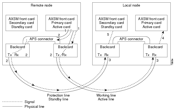
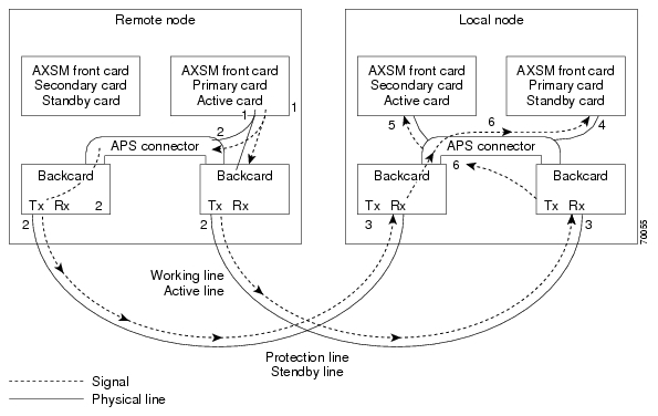
In AXSM and AXSM/B intercard APS, either front card can be active, and can be connected to either APS line through the APS connector joining the two back cards. The following process describes how intercard APS communication works:

1. The signal leaves the front card at the remote end of the line. (See Figure 1 and Figure 2.)

2. The signal passes through the APS connector and both back card transmit ports at the remote end of the line. (See Figure 1 and Figure 2.)

3. The signal travels through both communication lines to the receive ports on both back cards at the local end. (See Figure 1 and Figure 2.)

4. The active front card processes the signal that is received on the active line. (See Figure 1 and Figure 2.)

5. The standby card monitors only the status of the standby line. (See Figure 1 and Figure 2.)

6. If necessary, the signal passes through the APS connector to the front card. (See Figure 2.)


Note The front card monitors only one of the receive lines.


Figure 1 shows an example of how this process operates in a standard APS configuration, where the primary card monitors the working line and the secondary card monitors the protection line.

Figure 2 shows an example of how the APS communication process operates in a crossed APS configuration, where the secondary card monitors the working line that is attached to the primary card, and the primary card monitors the protection line that is connected to the secondary card.

Figure 1

Standard APS Configuration

Figure 2

Crossed APS Configuration

Line failures are always detected at the receive end of the line. This is where a switchover occurs when a failure is detected. Two different types of switchovers can occur, depending on whether the APS was configured as unidirectional or bidirectional in the cnfapsln command:

When a failure occurs on a line configured for unidirectional switching, the switch changes lines at the receive end only. A switchover is not necessary at the transmit end because the transmitting back cards send signals on both lines in the 1 +1 APS configuration.

When a failure occurs on a line configured for bidirectional switching, a switchover occurs at both ends of the line.

If the status of the standby line is good, a switchover from the failed active line to the standby is automatic.

Enter the cnfapsln command to enable an automatic switchover back to the working line after it recovers from a failure, as shown in the following example:

M8850_LA.1.AXSM.a > cnfapsln -w 1.1.1 -rv 2

Table 8 describes the configurable parameters for the cnfapsln command.

Table 8 cnfapsln Command Parameters

-w <working line>

Slot number, bay number, and line number of the active line to configure, in the format:

slot.bay.line

Example: -w 1.1.1

-sf <signal fault ber>

A number between 3 and 5 indicating the Signal Fault Bit Error Rate (BER), in powers of ten:

3 = 10-3

4 = 10-4

5 = 10-5

Example: -sf 3

-sd <SignalDegradeBER>

A power if 10 in the range 5-9 that indicates the Signal Degrade Bit Error Rate (BER):

5 = 10-5

6 = 10-6

7 = 10-7

8 = 10-8

9 = 10-9

Example: -sd 5

-wtr <Wait To Restore>

The number of minutes to wait after the failed working line has recovered, before switching back to the working line. The range is 5-12.

Example: -wtr 5

-dr <direction>

Determines whether the line is unidirectional or bidirectional.

1 = Unidirectional. The line switch occurs at the receive end of the line.

2 = Bidirectional. The line switch occurs at both ends of the line.

Note This optional parameter is not shown in the above example because you do not need to set it for a revertive line.

Example: -dr 2

-rv <revertive>

Determines whether the line is revertive or non-revertive.

1 = Non-revertive. You must manually switch back to a recovered working line.

2 = Revertive. APS automatically switches back to a recovered working line after the number of minutes set in the -wtr parameter.

Example: -rv 1


If you want to manually switch from one line to another, enter the switchapsln <bay> <line> <switchOption> command, as shown in the following example:

M8850_LA.1.AXSM.a > switchapsln 1 1 6
Manual line switch from protection to working succeeded on line 1.1.1

Table 9 describes the configurable parameters for the switchapsln command.

Table 9 switchapsln Command Parameters

Parameter
Description

bay

The working bay number to switch.

line

The working line number to switch.

switchOption

The method of performing the switchover.

1 = Clear previous user switchover requests. Return to working line only if the mode is revertive.

2 = Lockout of protection. Prevents specified APS pair from being switched over to the protection line. If the protection line is already active, the switchover is made back to the working line.

3 = Forced working to protection line switchover. If the working line is active, the switchover is made to the protection line unless the protection line is locked out or in the SF condition, or if a forced switchover is already in effect.

4 = Forced protection to working line switchover. If the protection line is active, the switch is made to the working line unless a request of equal or higher priority is in effect. This option has the same priority as option 3 (forced working to protection line switchover). Therefor, if a forced working to protection line switchover is in effect, it must be cleared before this option (forced protection to working line switchover) can succeed.

5 = Manual switchover from working to protection line unless a request of equal or higher priority is in effect.

6 = Manual switchover from protection to working line. This option is only available in the 1+1 APS architecture.

service switch

This is an optional parameter. When set to 1, this field causes all APS lines to switch to their protected lines.


Enter the dspapslns command to verify that the active line switched over from the protection line to the working line, as shown in the following example:

M8850_LA.1.AXSM.a > dspapslns
Working Prot.  Conf  Oper    Active  WLine PLine WTR   Revt Conf Oper LastUser
Index   Index  Arch  Arch    Line    State State (min)      Dir  Dir  SwitchReq
------- -----  ----  -----   ------  ----- ----- ----- ---- ---- ---- ----------
  1.1.1  2.1.1 1+1    1+1    working    OK    OK     5  Yes   bi   bi ManualP->W

Troubleshooting APS Lines

Port lights on AXSM and AXSM/B front cards indicate the receive status of APS lines. The active front card always displays the status of the active line. The standby card always displays the status of the inactive line. If only one APS line fails, the line failure LED is always displayed on the standby front card.


Caution When the active front card and the active line are in different slots and the inactive line has failed, it is easy to incorrectly identify the failed line as the line in the standby slot. To avoid disrupting traffic through the active line, verify which physical line is at fault before disconnecting the suspect line.

If the active line fails and the standby line is not available, the switch reports a critical alarm.

If the active line fails and the standby line takes over, the former standby line becomes the new active line, and the switch reports a major alarm.

If an AXSM front card fails, APS communication between the redundant front cards fails. This can result in one of the following situations:

If both APS lines were working before the failure, an APS line failure causes a switchover to the protection line

If either APS line failed prior to a front card failure, a failure on the active line does not cause a switchover to the other line. Because the standby front card failed, it cannot monitor the standby line and report when the line has recovered. This means that the active card cannot use the standby line until the standby front card is replaced and the line problem corrected.

Use the following procedure to troubleshoot APS lines.


Step 1 Enter the dsplns command to determine if the line in alarm is an APS line. The dsplns  command shows which lines are enabled for APS:

M8850_LA.1.AXSM.a > dsplns
                                           Medium Medium 
  Sonet  Line     Line     Line    Frame   Line   Line     Alarm   APS 
  Line  State     Type     Lpbk   Scramble Coding Type     State   Enabled
  ----- ----- ------------ ------ -------- ------ -------  -----   -------- 
   1.1     Up sonetSts12c NoLoop   Enable  Other ShortSMF    Clear Enable
   1.2     Up sonetSts12c NoLoop   Enable  Other ShortSMF    Clear Disable
   2.1     Up sonetSts12c NoLoop   Enable  Other ShortSMF    Clear Disable
   2.2     Up sonetSts12c NoLoop   Enable  Other ShortSMF    Clear Disable

If the line in alarm is an APS line, and has always functioned properly as an APS line, proceed to Step 2.

If the line in alarm has never functioned properly as an APS line, verify that the following are true:

redundant front and back cards are in the appropriate bays and are installed at both ends of the line.

cable is properly connected to both ends of the line.

enter the dspapsbkplane command to verify that the APS connector is installed properly at both ends of the line.

Step 2 Enter the dspapslns command at both ends of the communication line to determine whether one or both lines in an APS pair are bad. Use Table 10 to help you determine which APS line is not functioning properly.

Table 10 Troubleshooting APS Line Problems Using the dspaps Command

Active Line
Working Line
Protection Line
Working Line LED
Protection Line
LED
Description

Working

OK

OK

Green

Green

Active card is receiving signal on working and protection lines. This does not guarantee that transmit lines are functioning properly. You must view the status on remote switch.

Protection

SF

OK

Green

Red

Active card is receiving signal on the protection line. No signal received on the working line.

Working

OK

SF

Green

Red

Active card is receiving signal on the working line. No signal received on the protection line.

Working

SF

SF

Red

Red

Active card is not receiving signal from either line. The working line was the last line to work.

Protection

SF

SF

Red

Red

Active card is not receiving signal from either line. The protection line was the last line to work.

Working

UNAVAIL

UNAVAIL


The card set is not complete. One or more cards have failed or been removed. See Table 11 to troubleshoot card errors.


If one or both lines appear to be bad, determine whether the working or protection line is in alarm. Troubleshoot and correct the standby line first. Replace the components along the signal path until the problem is resolved.

If the dspapslns command at either end of the line indicates a front or back card problem, resolve that problem first. (See Table 11 to card problems).

If the dspapslns command shows a signal failure on the standby line, replace that line.

If the standby line is still down, replace the cards along the signal path.

Table 11 Troubleshooting Card Problems

APS Line Failure
Possible Cause

All lines in upper and lower bays

Suspect a bad or removed front card. If both front cards are good, both back cards may be bad.

All lines in upper bay only. Lower bay APS lines ok.

Suspect bad upper bay back card.

All lines in lower bay only. Upper bay APS lines OK.

Suspect bad lower bay back card.


Clearing the Configuration on Redundant PXM45 Cards

Due to checks to prevent an inserted card from affecting the system, an additional step may be required when inserting two "non-native" PXM45 cards in a shelf. Insert the first PXM45, do a clrallcnf, and allow this to become active before inserting the second PXM45.

Recommendations

Cisco Systems provides the following information and recommendations for switch configuration:

The RPM-PR subinterface ID range is 1 - 32767.

Apply the default values for PCR, SCR, and so on to the Control VC. If the values are decreased to a low value, there is a chance that the protocol on the interface (SSCOP or PNNI) will not come up.

Installing and Upgrading to Release 2.1.79


Note These procedures generally apply to installing Release 2.1.76 software on an MGX 8950 switch. However, Release 2.1.76 is the first release of software for the MGX 8950, so please disregard references to upgrading from a previous release of software.


You can gracefully upgrade to Release 2.1.79 from Release 2.1.76.

The procedures in this section are based on "Appendix A, Downloading and Installing Software Upgrades" in the "MGX 8850 and MGX 8950 Switch Software Configuration Guide, Release 2.1" (part DOC-7812551=). In this section, references to "chapters" refer to chapters in that manual.

You can download that manual from http://www.cisco.com/univercd/cc/td/doc/product/wanbu/8850r21/index.htm.


Caution Although graceful upgrades can be aborted with the abortrev command, the abortrev command does reset both active and standby cards, so reverting back to an earlier software release is not graceful. Please see the "abortrev" command description in the "Cisco MGX 8850 and MGX 8950 Switch Command Reference, Release 2.1" (part DOC-7812563=). A table under that command shows the behavior of cards in a single and redundant configuration.

This section describes how to locate, download, and install software updates for the switch. Because software updates are stored in the switch file system, this section includes a subsection on browsing the file system. This section includes the following subsections:

Upgrade Process Overview

Quickstart Procedures for Software Upgrades

Browsing the File System

Copying Software Files to the Switch

Upgrade Procedures for PXM45 and AXSM Cards

Upgrade Procedures for RPM-PR Cards

Using XModem to Download Flash to RPM Cards

Troubleshooting Upgrade Problems

Upgrade Process Overview

This section provides a series of quickstart procedures that describe how to perform graceful and non-graceful upgrades to the switch. To perform a graceful upgrade on a switch card, the card must be operating in redundant mode with another switch card of the same type. When performed properly, graceful upgrades have minimal impact on connections in progress and do not interrupt any established connections.


Note Graceful upgrades to Release 2.1.79 are supported from Release 2.1.76.


When a card to be upgraded is not operating in redundant mode, you must do a non-graceful upgrade, which disrupts all traffic that passes through the card. For PXM45 cards, an ungraceful upgrade interrupts all traffic passing through the switch. For all other types of cards, an ungraceful upgrade affects only the traffic that passes through that card.

Each type of switch card runs boot and runtime software. The recommended sequence for upgrading the software (i.e., firmware) on switch cards is as follows:

1. PXM45 boot software

2. PXM45 runtime software

3. AXSM boot software

4. AXSM runtime software

5. RPM-PR boot software

6. RPM-PR runtime software


Note If you plan to upgrade PXM45 cards and AXSM cards, upgrade the PXM45 cards first. Wait until the PXM45 cards are operating in active and standby modes with the correct software before upgrading AXSM cards. The software version used by the PXM45/B cards should be equal to or later than the version used on the AXSM/B card.


Typically, the boot software requires less frequent upgrades. However, in this release, both the boot and runtime software need to be upgraded.

When you upgrade the software on a switch card, proceed as follows:

Decide whether you are performing a graceful or non-graceful upgrade

Follow the appropriate quickstart procedure for that type of upgrade

For additional information on a task within a quickstart procedure, see the subsection to which the procedure refers

The next subsection presents the quickstart procedures for switch card software upgrades.

Quickstart Procedures for Software Upgrades

The following subsections provide quickstart procedures for the following upgrades:

Preparing for Upgrades

Graceful PXM45 Boot Upgrades

Non-Graceful PXM45 Boot Upgrades

Graceful PXM45 and AXSM Runtime Software Upgrades

Non-Graceful PXM45 and AXSM Runtime Software Upgrades

Graceful AXSM Boot Upgrades

Non-Graceful AXSM Boot Upgrades

RPM-PR Boot and Runtime Software Upgrades


Caution A CP port session is required because you will be resetting the node and entering commands in "Backup Boot mode," which is not accessible through other connection methods.

Preparing for Upgrades

Before you can upgrade the software on any card, you must copy the software to your switch and then log into the switch. The following table describes how to prepare for software upgrades on any card:

 
Command
Description

Step 1 

ftp

Copy the boot and runtime files you want to use to your switch.

FTP the AXSM and PXM45 boot and runtime images to the C:FW directory. FTP the RPM boot and runtime images to the E:RPM directory.

See "Copying Software Files to the Switch," which appears later in this section.

Step 2 

username

password

Establish a CLI session with the standby PXM45 card using the CP port on the UI-S3 back card and a user name with CISCO_GP privileges.

Step 3 

saveallcnf

This optional step saves the current configuration to the hard disk of the active PXM45/B card. (The command can only be issued on the active PXM card.)

Refer to "Saving a Configuration" in Chapter 7, "Switch Operating Procedures."

Graceful PXM45 Boot Upgrades

When performed properly, graceful upgrades have minimal impact on connections in progress and do not interrupt any established connections.

When a boot software upgrade is required, the procedure for upgrading redundant PXM45 cards updates the standby card and then makes that card active. This method ensures a smooth transition to the new software and preserves all established calls. Any calls that are not established are lost.

A graceful upgrade of the boot software does the following:

1. Loads the new software on the standby PXM45 card

2. Makes the standby PXM45 card active

3. Loads the new software on the formerly active (now standby) PXM45 card


Note Avoid making configuration changes while upgrading PXM45 software. Configuration changes can be lost when the PXM45 is reset during the upgrade.


To upgrade the runtime software, use the following procedure.

 
Command
Purpose

Step 1 


Copy the boot files you want to use to the switch and log into the active PXM45 card.

See "Upgrade Process Overview" section.

Step 2 

sysPxmRemove

At the backup boot prompt, enter the sysPxmRemove command: This step prevents the active card from resetting the standby card while you are working with it.

Step 3 

sysFlashBootBurn "Filename"

reboot

username

password

dspcds; dsprevs

Burn the boot software. Remember to enter quotation marks before and after the boot software filename. For example:

sysFlashBootBurn "C:FW/pxm45_002.001.075.015-A_bt.fw"

See "Upgrading PXM45 Boot Software" section.

Step 4 

username

password

Establish a CLI session with the active PXM45 card (which is the non-upgraded card) using the CP port on the UI-S3 back card and a user name with CISCO_GP privileges.

Step 5 

switchcc

y

Switch the roles of the active and standby cards so you can upgrade the non-upgraded card in standby mode.

Step 6 

sh

sysBackupBoot

<Return> (2.0.11 and earlier)

Using the CP port connection, change to the PXM45 Backup Boot mode.

Note that the software versions 2.0.11 and earlier require you to press Return during the reboot sequence to enter backup boot mode.

See "Changing to PXM45 Backup Boot Mode" in Appendix B, "PXM45 Backup Boot Procedures.".

Step 7 

sysPxmRemove

At the backup boot prompt, enter the sysPxmRemove command: This step prevents the active card from resetting the standby card while you are working with it.

Step 8 

sysFlashBootBurn "Filename"

reboot

username

password

dspcds; dsprevs

Burn the boot software. Remember to enter quotation marks before and after the boot software filename. For example:

sysFlashBootBurn "C:FW/pxm45_002.001.075.015-A_bt.fw"

See "Upgrading PXM45 Boot Software" section.

The boot software is now upgraded on both the active and standby cards. The card that was active before the upgrade is now operating in standby mode.

Non-Graceful PXM45 Boot Upgrades

Ungraceful upgrades disrupt all switch traffic and are usually used in lab installations where the use of standalone cards provides no opportunity for a graceful upgrade. The quickstart procedure is provided as an overview and as a quick reference.


Note Avoid making configuration changes while upgrading PXM45 software. Configuration changes can be lost when the PXM45 is reset during the upgrade.


Command
Purpose

Step 1 


Copy the boot files you want to use to the switch and log into the active PXM45 card.

See "Upgrade Process Overview" section.

Step 2 

sh

sysBackupBoot

<Return> (2.0.11 and earlier)

Using the CP port connection, change to the PXM45 Backup Boot mode.

Note that the software versions 2.0.11 and earlier require you to press Return during the reboot sequence to enter backup boot mode.

See "Changing to PXM45 Backup Boot Mode" in Appendix B, "PXM45 Backup Boot Procedures."

Step 3 

sysFlashBootBurn "Filename"

reboot

username

password

dspcd; dsprevs

Burn the boot software. Remember to enter quotation marks before and after the boot software filename. For example:

sysFlashBootBurn "C:FW/pxm45_002.001.075.015-A_bt.fw"

See "Upgrading PXM45 Boot Software" section.

Graceful PXM45 and AXSM Runtime Software Upgrades

When performed properly, graceful upgrades have minimal impact on connections in progress and do not interrupt any established connections.

This quickstart procedure applies to both PXM45 and AXSM cards and does the following:

1. Loads the new software on the standby PXM45 or AXSM card

2. Makes the standby card active

3. Loads the new software on the formerly active (now standby) card


Note If you plan to upgrade PXM45 cards and AXSM cards, upgrade the PXM45 cards first. Wait until the PXM45 cards are operating in active and standby modes with the correct software before upgrading AXSM cards. The software version used by the PXM45/B cards should be equal to or later than the version used on the AXSM/B card. When AXSM boot software is to be upgraded, it should be upgraded before upgrading the runtime software.


Note Avoid making configuration changes while upgrading PXM45 software. Configuration changes can be lost when the PXM45 is reset during the upgrade.


Note Upgrade software on the node to Release 2.1.75 or 2.1.76 before inserting the AXSM-E card.


To upgrade the runtime software, use the following procedure.

 
Command
Purpose

Step 1 


Copy the runtime files you want to use to the switch and log into the active PXM45 card.

See "Upgrade Process Overview" section.

Step 2 

dspcds; dsprevs; dsprevs -s

commitrev <slot> <revision>

Verify that all previous upgrades have been committed.

If a previous upgrade has not been committed, commit to the new upgrade.

See "Committing to a Runtime Software Upgrade" section.

Step 3 

loadrev <slot> <revision>

dspcds; dsprevs -s

Load the new runtime software on the standby card.

Step 4 

runrev <slot> <revision>

dspcds; dsprevs -s

dspcd <slot>

Switch over to the standby card and load the new runtime software on the new standby (non-upgraded) card.

Step 5 

commitrev <slot> <revision>

dspcds

dsprevs

dsprevs -s

This command prevents an accidental switch back to a previous software revision if someone enters the abortrev command. Enter the commitrev command after the former active card comes up in the standby-U state. Cisco Systems recommends that you avoid configuration changes until after you have run the commitrev or abortrev commands.

See "Aborting a Runtime Software Upgrade" section and "Committing to a Runtime Software Upgrade" section.

Non-Graceful PXM45 and AXSM Runtime Software Upgrades

Ungraceful upgrades disrupt all switch traffic and are usually used in lab installations where the use of standalone cards provides no opportunity for a graceful upgrade. The quickstart procedure is provided as an overview and as a quick reference.


Note If you plan to upgrade PXM45 cards and AXSM cards, upgrade the PXM45 cards first. Wait until the PXM45 cards are operating in active and standby modes with the correct software before upgrading AXSM cards. The software version used by the PXM45/B cards should be equal to or later than the version used on the AXSM/B card. When AXSM boot software is to be upgraded, it should be upgraded before upgrading the runtime software.


Note Avoid making configuration changes while upgrading PXM45 software. Configuration changes can be lost when the PXM45 is reset during the upgrade.


Note Upgrade software on the node to Release 2.1.70 or 2.1.75 before inserting the AXSM-E card.


Command
Purpose

Step 1 


Copy the runtime files you want to use to the switch and log into the active PXM45 card.

See "Upgrade Process Overview" section.

Step 2 

dspcds; dsprevs -s

commitrev <slot> <revision>

Verify that all previous upgrades have been committed.

If a previous upgrade has not been committed, commit to the new upgrade.

See "Committing to a Runtime Software Upgrade" section.

Step 3 

loadrev <slot> <revision>

dspcds; dsprevs -s

Define the new software version to be used.

Step 4 

runrev <slot> <revision>

dspcds; dsprevs -s

Reset the card and run the new runtime software version.

Step 5 

commitrev <slot> <revision>

dspcds

dsprevs -s

dsprevs

This command prevents an accidental switch back to a previous software revision if someone enters the abortrev command.

Cisco Systems recommends that you avoid configuration changes until after you have run the commitrev or abortrev commands.

See "Aborting a Runtime Software Upgrade" section and "Committing to a Runtime Software Upgrade" section.

Graceful AXSM Boot Upgrades

When performed properly, graceful upgrades have minimal impact on connections in progress and do not interrupt any established connections. The quickstart procedure is provided as an overview and as a quick reference.


Note If you plan to upgrade PXM45 cards and AXSM cards, upgrade the PXM45 cards first. Wait until the PXM45/B cards are operating in active and standby modes with the correct software before upgrading AXSM cards. The software version used by the PXM45/B cards should be equal to or later than the version used on the AXSM/B card.


Note Upgrade software on the node to Release 2.1.75 or Release 2.1.76 before inserting the AXSM-E card.


Command
Purpose

Step 1 


Copy the boot files you want to use to the switch and log into the active PXM45 card.

See "Upgrade Process Overview", which appears earlier in this section.

Step 2 

burnboot <slot> <revision>

dspcd <slot>

dsprevs

Burn the boot software on the standby AXSM card by specifying the slot number of the standby card.

See "Upgrading Boot Software on an AXSM Card," which appears later in this section.

Step 3 

switchredcd <fromSlot> <toSlot>

Activate the upgraded card and place the non-upgraded card in standby mode.

Step 4 

burnboot <slot> <revision>

dspcd <slot>

dsprevs

Burn the boot software on the non-upgraded, standby AXSM card by specifying the slot number of the standby card.

See "Upgrading Boot Software on an AXSM Card," which appears later in this section.

Non-Graceful AXSM Boot Upgrades

Ungraceful upgrades disrupt all switch traffic and are usually used in lab installations where the use of standalone cards provides no opportunity for a graceful upgrade. The quickstart procedure is provided as an overview and as a quick reference.


Note If you plan to upgrade PXM45 cards and AXSM cards, upgrade the PXM45 cards first. Wait until the PXM45 cards are operating in active and standby modes with the correct software before upgrading AXSM cards. The software version used by the PXM45/B cards should be equal to or later than the version used on the AXSM/B card.


Note Upgrade software on the node to Release 2.1.75 or Release 2.1.76 before inserting the AXSM-E card.


Command
Purpose

Step 1 


Copy the boot files you want to use to the switch and log into the active PXM45 card.

See "Upgrade Process Overview", which appears earlier in this section.

Step 2 

burnboot <slot> <revision>

dspcd <slot>

dsprevs

Burn the boot software on the standby AXSM card by specifying the slot number of the standby card.

See "Upgrading Boot Software on an AXSM Card," which appears later in this section.

RPM-PR Software Upgrades for Cards with 1:N Redundancy

On the MGX 8950, the RPM cards can go into slots 1 through 6, or 11 through 14.

The RPM-PR card supports software upgrades when 1:N redundancy is established in the switch between RPM-PR cards. Boot software is generally upgraded less often than runtime software, so be sure to compare the recommended boot software version with the boot software running on your RPMs before starting an upgrade. The correct boot software might already be installed.

The following quickstart procedure describes how to upgrade redundant RPM-PR cards. For detailed instructions, see "Upgrade Procedures for RPM-PR Cards," which appears later in this section.

These procedures describe how to upgrade boot as well as runtime software together or runtime software only.


Note Redundancy must be established before you use this procedure. If redundancy has not been configured between two RPM-PR cards, upgrade each RPM-PR card using the procedure in "RPM-PR Software Upgrades for Non-Redundant Cards," which appears later in this chapter. To add redundancy to an RPM-PR card, refer to "Establishing Redundancy Between Two RPM-PR Cards" in Chapter 4, "Preparing RPM-PR Cards for Operation" of the Cisco MGX 8850 and MGX 8950 Switch Software Configuration Guide, Release 2.1.


Table 12

 
Command
Purpose

Step 1 


Copy the files you want to use to the E:RPM directory of the switch and log in your switch.

See "Upgrade Process Overview"," which appears earlier in this section.

Step 2 

username

password

Establish a CLI session with the active PXM45 card using a user name at any access level.

Step 3 

copy

Copy and rename the runtime file to a generic name for easy updates.

See "Non-Graceful RPM-PR Runtime Software Upgrades," which appears later in this chapter.

Note If you have already configured the RPM to use a generic name, you can skip to Step 16.

Step 4 

cc <primarySlot>

Select the slot in which the primary RPM-PR card is installed.

Step 5 

enable

password

Enter Enable mode for the router.

Step 6 

dir e:

Verify router access to the PXM45 hard disk and the boot upgrade software.

Step 7 

show flash:

Display current contents of bootflash.

Step 8 

copy filename bootflash:

dir bootflash:

Copy the upgrade boot software to flash. For example:

copy e:rpm-boot-mz_002.001.060.000 bootflash:

Step 9 

del bootflash:

Delete older boot files from the bootflash. The switch always attempts to load the first bootable file in bootflash. If the upgraded file has a higher file number than another bootable file, it will not be used when the card is reset.

Note This step marks files to be deleted, but it does not delete them.

Step 10 

show flash:


Caution Verify that at least one valid boot or runtime image will not be deleted. If all boot and runtime images are deleted from bootflash, the RPM card must be returned to the factory for repair.

Step 11 

squeeze flash:

This step deletes all files that have been marked for deletion.

Step 12 

copy

Optional: Copy and rename the runtime file to a generic name for easy updates.

See "Non-Graceful RPM-PR Runtime Software Upgrades," which appears later in this chapter.

Note If you have already configured the RPM to use a generic name, you can skip to Step 21.

Step 13 

show bootvar

Display the current runtime software filename.

Step 14 

config terminal

Enter the router global configuration mode.

Step 15 

no boot system

Remove the entire boot list. To remove a single file from the boot list, include a filename. For example:

Router(config)# no boot system c:rpm-js-mz_122-4.T

Step 16 

boot system c:filename

Add the new router runtime image to the boot list. For example:

Router(config)# boot system c:rpm-js-mz_122-4.T

Step 17 

boot config e:auto_config_RPM-PR_slot#

Configure the RPM-PR card to store its configuration on the PXM45 hard disk.

Note This step only needs to be performed once. If this command is already in the startup configuration file, you do not need to enter it again.

Step 18 

^Z

Exit global configuration mode.

Step 19 

copy run start

Save the new configuration.

Note If you omit this step, the RPM-PR card will continue to use the previous version of software.

Step 20 

show bootvar

Verify the change in the runtime software filename.

Step 21 

switchredcd <primarySlot> <secondarySlot>

This step makes the secondary card active and resets the primary RPM-PR card. When the primary card resets, it loads the upgraded boot software from bootflash.

Step 22 

cc <secondarySlot>

Select the slot in which the secondary RPM-PR card is installed.

Step 23 

enable
password
dir e:
show flash:
copy
filename bootflash:
dir bootflash:
show flash:
squeeze flash:

Repeat Step 5 through Step 11 to move the upgraded boot software into bootflash.

Step 24 

show bootvar

config terminal

no boot system

boot system c:filename

^Z

copy run start

show bootvar

Repeat Step 13 through Step 16 andStep 18 through Step 20 to upgrade runtime software.

Step 25 

switchredcd <secondarySlot> <primarySlot>

This step makes the upgraded primary card active and resets the secondary RPM-PR card. When the secondary card resets, it loads the upgraded boot software from bootflash. Both primary and secondary cards should now be using upgraded boot software.

Step 26 


If there are other primary RPM-PR cards that need upgrading, repeat the part of this procedure that upgrades the primary card, then execute the switchredcd command once to reload the primary card. Finally, execute the switchredcd command a second time to make the upgraded primary card active.

RPM-PR Boot Software and Runtime Software Upgrades Together

RPM-PR Runtime Software Upgrade for Cards with 1:N Redundancy (no boot software upgrade)

The RPM-PR card supports upgrades when 1:N redundancy is established in the switch between RPM-PR cards.

The following quickstart procedure describes how to gracefully upgrade redundant RPM-PR cards.


Note Redundancy must be established before you use this procedure. If redundancy has not been configured between two RPM-PR cards, upgrade each RPM-PR card as described in "RPM-PR Runtime Software Upgrades for Non-Redundant Cards," which appears later in this chapter. To add redundancy to an RPM-PR card, refer to "Establishing Redundancy Between Two RPM-PR Cards" in Chapter 4, "Preparing RPM-PR Cards for Operation."


Table 13

 
Command
Purpose

Step 1 


Copy the files you want to use to the E:RPM directory of the switch and log in your switch.

See "Upgrade Process Overview"," which appears earlier in this section.

Step 2 

username

password

Establish a CLI session with the active PXM45 card using a user name at any access level.

Step 3 

copy

Copy and rename the runtime file to a generic name for easy updates.

See "Non-Graceful RPM-PR Runtime Software Upgrades," which appears later in this chapter.

Note If you have already configured the RPM to use a generic name, you can skip to Step 16.

Step 4 

cc <primarySlot>

Select the slot in which the primary RPM-PR card is installed.

Step 5 .

enable

password

Enter Enable mode for the router.

Step 6 

show bootvar

Display the current runtime software filename.

Step 7 

config terminal

Enter the router global configuration mode.

Step 8 

no boot system

Remove the entire boot list. To remove a single file from the boot list, include a filename. For example:

Router(config)# no boot system c:rpm-js-mz_122-4.T

Step 9 

boot system c:filename

Add the new router runtime image to the boot list. For example:

Router(config)# boot system c:rpm-js-mz_122-4.T

Step 10 

boot config e:auto_config_RPM-PR_slot#

Configure the RPM-PR card to store its configuration on the active PXM45 hard disk.

Note This step only needs to be performed once. If this command is already in the startup configuration file, you do not need to enter it again.

Step 11 

^Z

Exit global configuration mode.

Step 12 

copy run start

Save the new configuration.

Note If you omit this step, the RPM-PR card will continue to use the previous version of software.

Step 13 

show bootvar

Verify the change in the runtime software filename.

Step 14 

switchredcd <primarySlot> <secondarySlot>

This step makes the secondary card active and resets the primary RPM-PR card. When the primary card resets, it loads the upgraded boot software from bootflash.

Step 15 

cc <secondarySlot>

Select the slot in which the secondary RPM-PR card is installed.

Step 16 

enable

password

show bootvar

config terminal

no boot system

boot system c:filename

^Z

copy run start

show bootvar

Repeat Step 5 through Step 9 and Step 11 through Step 13.

Step 17 

switchredcd <secondarySlot> <primarySlot>

This step makes the upgraded primary card active and resets the secondary RPM-PR card. When the secondary card resets, it loads the upgraded boot software from bootflash. Both primary and secondary cards should now be using upgraded runtime software.

Step 18 


If there are other primary RPM-PR cards that need upgrading, repeat the part of this procedure that upgrades the primary card, then execute the switchredcd command once to reload the primary card. Finally, execute the switchredcd command a second time to make the upgraded primary card active.

RPM-PR Runtime Software Upgrade (no boot upgrade)

RPM-PR Software Upgrades for Non-Redundant Cards

Use the software upgrade procedure in this subsection when you need to upgrade RPM-PR boot software and the RPM-PR is operating in standalone mode.


Note If the RPM-PR is operating in 1:N redundancy mode with another RPM-PR, upgrade the cards as described in "RPM-PR Software Upgrades for Cards with 1:N Redundancy," which appears earlier in this chapter.


The following quickstart procedure is provided as an overview and as a quick reference for those who have already performed RPM-PR upgrades on the switch. For detailed instructions, see "Upgrade Procedures for RPM-PR Cards," which appears later in this section.

Table 14

 
Command
Purpose

Step 1 

ftp

Copy the boot and runtime files you want to use to the switch (E:RPM).

See "Copying Software Files to the Switch," which appears later in this section.

Step 2 

username

password

Establish a CLI session with the active PXM45 card using a user name at any access level.

Step 3 

copy

Copy and rename the runtime file to a generic name for easy updates.

See "Non-Graceful RPM-PR Runtime Software Upgrades," which appears later in this chapter.

Note If you have already configured the RPM to use a generic name, you can skip to Step 12.

Step 4 

cc <RPM-PR_Slot>

Select the slot in which the RPM-PR card is installed.

Step 5 

enable

password

Enter Enable mode for the router.

Step 6 

dir e:

Verify router access to the active PXM45 hard disk and the boot upgrade software.

Step 7 

show flash:

Display current contents of bootflash.

Step 8 S

copy filename bootflash:

dir bootflash:

Copy the upgrade boot software to flash. For example:

copy e:rpm-boot-mz_002.001.075.015-A bootflash:

Step 9 

del bootflash:

Optional. Delete older boot files from the bootflash. This step marks files to be deleted, but it does not delete them.

Step 10 

show flash:


Caution Verify that at least one valid boot or runtime image will not be deleted. If all boot and runtime images are deleted from bootflash, the RPM card must be returned to the factory for repair.

Step 11 

squeeze flash:

This step deletes all files that have been marked for deletion.

Step 12 

show bootvar

Display the current runtime software filename.

Step 13 

config terminal

Enter the router global configuration mode.

Step 14 

no boot system

Remove the entire boot list. To remove a single file from the boot list, include a filename. For example:

Router(config)# no boot system c:rpm-js-mz_122-4.T

Step 15 

boot system e:filename

Add the new router runtime image to the boot list. For example:

Router(config)# boot system e:rpm-js-mz.122-4.T

Step 16 

boot config e:auto_config_RPM-PR_slot#

Configure the RPM-PR card to store its configuration on the PXM45 hard disk.

Note This step only needs to be performed once. If this command is already in the startup configuration file, you do not need to enter it again.

Step 17 

^Z

copy run start

Exit global configuration mode and save the new configuration.

Step 18 

show bootvar

Verify the change in the runtime software filename.

Step 19 

cc <active_PXM45_slot>

resetcd <RPM-PR_Slot>

This command sequence restarts the RPM-PR card with the new boot image.

RPM-PR Boot and Runtime Software Upgrade (Together)

Non-Graceful RPM-PR Runtime Software Upgrades (no boot software upgrade)

Use the software upgrade procedure in this section when you need to upgrade RPM-PR runtime software and the RPM-PR is operating in standalone mode.


Note If the RPM-PR is operating in 1:N redundancy mode with another RPM-PR, upgrade the cards as described in "RPM-PR Software Upgrades for Cards with 1:N Redundancy," which appears earlier in this chapter.


The following quickstart procedure is provided as an overview and as a quick reference for those who have already performed RPM-PR upgrades on the switch. For detailed instructions, see "Upgrade Procedures for RPM-PR Cards," which appears later in this section.

Table 15

 
Command
Purpose

Step 1 

ftp

Copy the boot and runtime files you want to use to the switch (E:RPM).

See "Copying Software Files to the Switch," which appears later in this section.

Step 2 

copy

Copy and rename the runtime file to a generic name for easy updates.

See "Non-Graceful RPM-PR Runtime Software Upgrades," which appears later in this chapter.

Note If you have already configured the RPM to use a generic name, you can skip to Step 12.

Step 3 

username

password

Establish a CLI session with the active PXM45 card using a user name at any access level.

Step 4 

cc <RPM-PR_Slot>

Select the slot in which the RPM-PR card is installed.

Step 5 

enable

password

Enter Enable mode for the router.

Step 6 

show bootvar

Display the current runtime software filename.

Step 7 

config terminal

Enter the router global configuration mode.

Step 8 

no boot system

Remove the entire boot list. To remove a single file from the boot list, include a filename. For example:

Router(config)# no boot system c:rpm-js-mz_122-4.T

Step 9 

boot system e:filename

Add the new router runtime image to the boot list. For example:

Router(config)# boot system e:rpm-js-mz.122-4.T

Step 10 

boot config e:auto_config_RPM-PR_slot#

Configure the RPM-PR card to store its configuration on the PXM45 hard disk.

Note This step only needs to be performed once. If this command is already in the startup configuration file, you do not need to enter it again.

Step 11 

^Z

copy run start

Exit global configuration mode and save the new configuration.

Step 12 

show bootvar

Verify the change in the runtime software filename.

Step 13 

cc <active_PXM45_slot>

resetcd <RPM-PR_Slot>

This command sequence selects the active PXM card and restarts the RPM card with the new runtime image.

Step 14 

dspcds

dspcd <RPM-PR_Slot>

cc <RPM-PR_Slot>

Verify router reboot is complete.

RPM-PR Runtime Software Upgrades (no boot software upgrade)

Browsing the File System

The active PXM45 hard disk stores log files, configuration files, and boot and runtime software. The switch operating system supports a set of UNIX-like commands that you can use to locate log files or manage software updates. Table 16 lists commands that you can use to browse the file system.


Note File and directory names in the switch file system are case sensitive. Also, some of the commands listed in Table 16 are not available at all administrator access levels.


Table 16 File System Commands at Switch Prompt 

Command
Description

cd

Change directories. Access level required: ANYUSER or above.

copy

Copies a file from one location to another.

Syntax: copy <source file name> <destination file name>

Access level required: GROUP1 or above.

del

Deletes a file.

Syntax: del <file name>

Access level required: GROUP1 or above.

ll

List directory contents using long format, which includes the name, size, modification date, and modification time for each file. This command also displays the total disk space and free disk space.

Syntax: ll

Access level required: ANYUSER or above.

ls

List directory contents using the short format, which displays filenames, total disk space, and free disk space.

Syntax: ls

Access level required: ANYUSER or above.

pwd

Display the present working directory.

Syntax: pwd

Access level required: ANYUSER or above.

rename

Renames a file.

Syntax: rename <old file name> <new file name>

Access level required: GROUP1 or above.

whoami

Lists the login name for the current session.

Syntax: whoami

Access level required: ANYUSER or above.


Copying Software Files to the Switch

This section describes how to copy software files to the MGX 8950 switch. The switch cards use boot software and runtime software. Each PXM45 and AXSM card uses the boot software to define communications between the card components and to enable cards to start up. The runtime software defines how the card operates after startup. RPM-PR cards function on the runtime software and use the boot software only when they cannot load the runtime software.


Note The boot and runtime software are installed on the switch at the factory. Before you copy new files to the switch, verify that you need to update the files by comparing the file versions on the disk to the file versions in Table 3.


The MGX 8950 switches provide a File Transfer Protocol (FTP) service to support file transfers to the switch. If you have FTP client software and network connectivity to both the switch and the server where the software files are stored, you can use FTP to transfer files directly from the server to the switch.


Note The following procedure describes how to copy files to the switch when the runtime software is up and running (showing the node name switch prompt). When the runtime software cannot load, copy the software files to the switch as described in "Transferring Software Files to and from the Switch" in Appendix B, "PXM45 Backup Boot Procedures."


Step 1 Locate the files you want to download from http://www.cisco.com/kobayashi/sw-center/wan/wan-planner.shtml.

Step 2 Using a workstation with FTP client software, transfer PXM45 and AXSM files from the server to the switch directory C:/FW.

The procedure you use for transferring the files depends on the FTP client software you are using. When initiating the FTP connection, remember the following:

Select the switch by entering its IP address.

When prompted for a username and password, enter the username and password you use when managing the switch.

When configuring file transfer options, select binary mode for the file transfer.

Step 3 To verify that the new PXM45 and AXSM files have been transferred to the switch, log into the switch and display the contents of the C:/FW directory.

Step 4 Using a workstation with FTP client software, transfer RPM-PR files from the server to the switch directory E:/RPM.


Note You must use a capital E when referencing the E drive in switch commands.


Step 5 To verify that the new RPM-PR files have been transferred to the switch, log into the switch and display the contents of the E:/RPM directory.

For more information on browsing the switch file system, see "Browsing the File System," which appears earlier in this section.


Upgrade Procedures for PXM45 and AXSM Cards

The following sections describe procedures that support upgrades to PXM45 and AXSM cards. For complete upgrade procedures, see "Quickstart Procedures for Software Upgrades," which appears earlier in this section. The procedures in this section detail some of the tasks listed in the quickstart procedures.

Upgrading PXM45 Boot Software

This section describes how to upgrade the PXM45 boot software on a single PXM45 card. If you are performing a graceful upgrade, use the quickstart procedure described in "Graceful PXM45 Boot Upgrades," which appears earlier in this section. The following procedure provides detailed information on the upgrade task within the quickstart procedure.


Step 1 If you have not done so already, establish a CLI session with the active PXM45 card using the CP port on the UI-S3 back card and a user name with CISCO_GP privileges.

Step 2 If you have not done so already, change to PXM45 Backup Boot mode as described in "Changing to PXM45 Backup Boot Mode" in Appendix B, "PXM45 Backup Boot Procedures.".

Step 3 To burn the boot software on the PXM45, enter the sysFlashBootBurn command as follows:

pxm45bkup> sysFlashBootBurn "filename"

Replace filename with the complete path to the boot file on the PXM45 hard drive. For example:

pxm45bkup> sysFlashBootBurn "C:FW/pxm45_002.001.075.015-A_bt.fw"

Step 4 When the switch prompts you to confirm this action, type y and press Return.

When the boot software burning process is complete, the switch displays a message similar to the following:

Flash download completed ... 
value = 0 = 0x0

Step 5 When the boot software has been burned, reset the card with the reboot command. For example:

pxm45bkup> reboot

Be patient and wait for Login prompt to appear.

Step 6 When the Login prompt appears, log in to the switch as you do at the beginning of a CLI session. The switch prompt should appear.

M8850_NY.8.PXM.a > 

Step 7 To confirm that the PXM45 card is now using the correct boot software, enter the dsprevs command.

M8850_NY.8.PXM.a > dsprevs
M8850_NY                         System Rev: 02.01   Feb. 11, 2002 17:01:54 PST
MGX8850                                              Node Alarm: CRITICAL
Physical  Logical   Inserted       Cur Sw              Boot FW             
Slot      Slot      Card           Revision            Revision            
--------  -------   --------       --------            --------            

01        01        AXSM_4OC12     2.1(70.202)         2.1(70.202)         
02        01        AXSM_4OC12     2.1(70.202)         2.1(70.202)         
03        03        AXSM_4OC12     2.1(70.202)         2.1(70.202)         
04        04        ---            ---                 ---                 
05        05        ---            ---                 2.1(70.202)         
06        06        ---            ---                 2.1(70.202)         
07        07        PXM45          2.1(70.202)         2.1(70.202)         
08        07        PXM45          2.1(70.202)         2.1(70.202)         
09        09        RPM_PR         ---                 ---                 
10        10        ---            ---                 ---                 
11        11        ---            ---                 ---                 
12        12        ---            ---                 ---                 
13        13        ---            ---                 ---                 
14        14        ---            ---                 --- 

Step 8 Use dspcd to see the condition of the PXM45 card. You should see active/active and no card alarm.

The Boot FW Rev row in the display should show the new revision as shown in the following example:

8850_NY.7.PXM.a > dspcd
8850_NY                          System Rev: 02.01   Mar. 04, 2001 22:47:23 PST
MGX8850                                              Node Alarm: NONE
Slot Number    7    Redundant Slot:  8

                    Front Card          Upper Card          Lower Card
                    ----------          ----------          ----------

Inserted Card:      PXM45               UI Stratum3         PXM HardDiskDrive  
Reserved Card:      PXM45               UI Stratum3         PXM HardDiskDrive  
State:              Active              Active              Active         
Serial Number:      SBK050302AF         SBK045203PJ         SBK044602HJ 
Prim SW Rev:        2.1(70)             ---                 ---
Sec SW Rev:         2.1(70)             ---                 ---
Cur SW Rev:         2.1(70)             ---                 ---
Boot FW Rev:        2.1(75)              ---                 ---
800-level Rev:      A0                  A0                  A0   
800-level Part#:    800-06147-08        800-05787-02        800-05052-04
CLEI Code:          BAA670YCAA          BA7IBCLAAA          BA7IADNAAA 
Reset Reason:       On Power up
Card Alarm:         NONE                
Failed Reason:      None                
Miscellaneous Information:

Type <CR> to continue, Q<CR> to stop:

After you confirm the upgrade to the first PXM45 card, the boot software upgrade for that card is complete.


Loading the Runtime Upgrade Software

This section describes how to load the runtime upgrade software in preparation for running it. Production switches should have redundant cards installed, so that upgrades can occur without interrupting traffic. For graceful upgrades, the upgrade software is loaded on the standby card first, and then the control is switched to upgraded card so that the other card can be upgraded.

The best way to assess the boot software upgrade status of a card is to enter the dsprevs command (without any parameters), as in the following example:

M8850_NY.8.PXM.a > dsprevs
M8850_NY                         System Rev: 02.01   Feb. 11, 2002 17:14:58 PST
MGX8850                                              Node Alarm: CRITICAL
Physical  Logical   Inserted       Cur Sw              Boot FW             
Slot      Slot      Card           Revision            Revision            
--------  -------   --------       --------            --------            

01        01        AXSM_4OC12     2.1(70.202)         2.1(70.202)         
02        01        AXSM_4OC12     2.1(70.202)         2.1(70.202)         
03        03        AXSM_4OC12     2.1(70.202)         2.1(70.202)         
04        04        ---            ---                 ---                 
05        05        ---            ---                 2.1(70.202)         
06        06        ---            ---                 2.1(70.202)         
07        07        PXM45          2.1(70.202)         2.1(70.202)         
08        07        PXM45          2.1(70.202)         2.1(70.202)         
09        09        RPM_PR         ---                 ---                 
10        10        ---            ---                 ---                 
11        11        ---            ---                 ---                 
12        12        ---            ---                 ---                 
13        13        ---            ---                 ---                 
14        14        ---            ---                 --- 

The current (Cur SW Revision) software revision label indicates the status of an upgrade for runtime 
software. The boot (Boot FW Revision) label indicates the status of an upgrade for the boot software. 

To assess the runtime software upgrade status of a card, enter the dsprevs -s command. For example:

M8850_NY.8.PXM.a > dsprevs -s
M8850_NY                         System Rev: 02.01   Feb. 11, 2002 17:10:49 PST
MGX8850                                              Node Alarm: CRITICAL
Phy. Log. Cur Sw           Prim Sw          Sec Sw           Rev Chg           
Slot Slot Revision         Revision         Revision         Status            
---- ---- --------         --------         --------         -------           

01   01   2.1(70.202)      2.1(70.202)      2.1(70.202)      ---               
02   01   2.1(70.202)      2.1(70.202)      2.1(70.202)      ---               
03   03   2.1(70.202)      2.1(70.202)      2.1(70.202)      ---               
04   04   ---              ---              ---              ---               
05   05   ---              2.1(70.79)P1     2.1(70.79)P1     ---               
06   06   ---              2.1(70.79)P1     2.1(70.79)P1     ---               
07   07   2.1(70.202)      2.1(70.202)      2.1(70.202)      ---               
08   07   2.1(70.202)      2.1(70.202)      2.1(70.202)      ---               
09   09   ---              ---              ---              ---               
10   10   ---              ---              ---              ---               
11   11   ---              ---              ---              ---               
12   12   ---              ---              ---              ---               
13   13   ---              ---              ---              ---               
14   14   ---              ---              ---              --- 

The current (Cur SW Revision), primary (Prim SW Revision), and secondary (Sec SW Revision) runtime software revision labels indicate the status of an upgrade for runtime software. In this example, these numbers match because the software upgrade has not started.

The primary software revision indicates which revision a card will run if it becomes active, and the secondary revision indicates an alternate revision that the card will use if the abortrev command is entered. (For more information on aborting an upgrade, see "Aborting a Runtime Software Upgrade," which appears later in this section.) The current software revision represents the software the active card is using. During a runtime upgrade, the Rev Change Status column shows when the revision command is in progress and subsequently when it is done.

The normal sequence of commands for a runtime software upgrade is loadrev, runrev, and commitrev. Table 17 shows how the software revision levels change during a graceful runtime software upgrade. Software Versions Reported During Graceful Upgrades

Table 17 Software Versions Reported During Graceful Upgrades

Software Revision
Before Upgrade
After loadrev
After runrev
After commitrev
Slot 7
Slot 8
Slot 7
Slot 8
Slot 7
Slot 8
Slot 7
Slot 8
Active
Standby
Active
Standby
Standby
Active
Active
Standby

Primary

2.1(70)

2.1(70)

2.1(70)

2.1(70)

2.1(75)

2.1(75)

2.1(75)

2.1(75)

Secondary

2.1(70)

2.1(70)

2.1(75)

2.1(75)

2.1(70)

2.1(70)

2.1(75)

2.1(75)

Current

2.1(70)

2.1(70)

2.1(70)

2.1(75)

2.1(75)

2.1(75)

2.1(75)

2.1(75)


For non-graceful upgrades, the load process defines the software version to which the switch is about to be upgraded. Table 18 shows how the revision levels change during a non-graceful upgrade.

Table 18 Software Versions Reported During Non-Graceful Upgrades

Software Revision
Before Upgrade
After loadrev
After runrev
After commitrev

Primary

2.1(70)

2.1(70)

2.1(75)

2.1(75)

Secondary

2.1(70)

2.1(75)

2.1(70)

2.1(75)

Current

2.1(70)

2.1(70)

2.1(75)

2.1(75)


If you are performing a graceful upgrade, use the quickstart procedure described in "Graceful PXM45 and AXSM Runtime Software Upgrades," which appears earlier in this section. The following procedure provides detailed information on the load task within the quickstart procedure.


Step 1 To load the upgrade runtime software version on a PXM45 or AXSM card, enter the following command:

mgx8950a.7.PXM.a > loadrev <slot> <revision>

Replace <slot> with the card slot number for the card to be upgraded, and replace <revision> with the software version number for the update. For graceful upgrades, you can specify either the active or the standby card. The switch software will automatically load the upgrade runtime software on the standby card when it is installed. The following example shows how to enter this command:

mgx8950a.7.PXM.a > loadrev 7 2.1(75)

After you enter the loadrev command, the standby card comes up in the standby-U state.

You can find the software version number in Table 3. You can also determine the version number from the runtime software filename as described in "Determining the Software Version Number from Filenames," which appears in Chapter 7, "Switch Operating Procedures."

Step 2 When prompted to confirm the command, type y and press Return to continue.

Step 3 To verify that the load command was processed correctly, enter the dsprevs -s command and check the status of the software revision levels.

M8850_NY.8.PXM.a > dsprevs -s
M8850_NY                         System Rev: 02.01   Feb. 11, 2002 01:16:26 PST
MGX8850                                              Node Alarm: CRITICAL
Phy. Log. Cur Sw           Prim Sw          Sec Sw           Rev Chg           
Slot Slot Revision         Revision         Revision         Status            
---- ---- --------         --------         --------         -------           

01   01   2.1(70.202)      2.1(70.202)      2.1(70.202)      ---               
02   01   2.1(70.202)      2.1(70.202)      2.1(70.202)      ---               
03   03   2.1(70.202)      2.1(70.202)      2.1(70.202)      ---               
04   04   ---              ---              ---              ---               
05   05   ---              2.1(70.79)P1     2.1(70.79)P1     ---               
06   06   ---              2.1(70.79)P1     2.1(70.79)P1     ---               
07   07   2.1(70.202)      2.1(70.202)      2.1(70.202)      ---               
08   07   2.1(70.202)      2.1(70.202)      2.1(70.202)      ---               
09   09   ---              ---              ---              ---               
10   10   ---              ---              ---              ---               
11   11   ---              ---              ---              ---               
12   12   ---              ---              ---              ---               
13   13   ---              ---              ---              ---               
14   14   ---              ---              ---              --- 

Note In a standalone configuration, the switch does not start the upgraded runtime software until the runrev command is entered. In a redundant configuration, the switch starts the upgraded runtime software on the standby card. The standby card does not become active until the runrev command is entered.


Activating the Upgraded Runtime Software

After you load the upgraded runtime software for a PXM45 or AXSM card, enter the runrev command to start using the software. The version levels for graceful and non-graceful upgrades change as shown earlier in Table 17 and Table 18. The following procedure describes how to activate the upgraded runtime software.


Step 1 To start using the new runtime software version on a PXM45 or AXSM card, enter the following command:

mgx8950a.7.PXM.a > runrev <slot> <revision>

Replace <slot> with the card slot number, and replace <revision> with the software version number specified with the loadrev command. For graceful upgrades, you can specify either the active or the standby card. The switch software will automatically run the upgrade runtime software on the standby card when it is installed. The following example shows how to enter this command:

mgx8950a.7.PXM.a > runrev 7 2.1(75)

The active card is reset, and the former standby card comes up in the active-U state.

Step 2 When prompted to confirm the command, type y and press Return to continue.

Step 3 To verify that the load command was processed correctly, enter the dsprevs -s command and check the status of the software revision levels.

M8850_NY.8.PXM.a > dsprevs -s
M8850_NY                         System Rev: 02.01   Feb. 11, 2002 01:16:26 PST
MGX8850                                              Node Alarm: CRITICAL
Phy. Log. Cur Sw           Prim Sw          Sec Sw           Rev Chg           
Slot Slot Revision         Revision         Revision         Status            
---- ---- --------         --------         --------         -------           

01   01   2.1(70.202)      2.1(70.202)      2.1(70.202)      ---               
02   01   2.1(70.202)      2.1(70.202)      2.1(70.202)      ---               
03   03   2.1(70.202)      2.1(70.202)      2.1(70.202)      ---               
04   04   ---              ---              ---              ---               
05   05   ---              2.1(70.79)P1     2.1(70.79)P1     ---               
06   06   ---              2.1(70.79)P1     2.1(70.79)P1     ---               
07   07   2.1(70.202)      2.1(70.202)      2.1(70.202)      ---               
08   07   2.1(70.202)      2.1(70.202)      2.1(70.202)      ---               
09   09   ---              ---              ---              ---               
10   10   ---              ---              ---              ---               
11   11   ---              ---              ---              ---               
12   12   ---              ---              ---              ---               
13   13   ---              ---              ---              ---               
14   14   ---              ---              ---              --- 

Step 4 When the former active PXM45 comes up in the standby-U state, enter the commitrev command to commit to that software version. This step is optional. The dsprevs -s command shows that runrev is done.

After the runrev command is entered, the switch starts running the new runtime software revision. The secondary software revision shows that a previous revision is still available. Whenever the secondary runtime software revision is different from the primary and current runtime software revisions, you can revert back to the secondary software revision as described in "Aborting a Runtime Software Upgrade," which appears later in this section.


Upgrading Boot Software on an AXSM Card


Note The AXSM upgrade procedures are the same for AXSM and AXSM/B cards.


The upgrade procedure for the boot software on a single AXSM card is the same for graceful and non-graceful upgrades. The difference between the graceful and non-graceful boot software upgrades is the sequence of commands before and after the upgrade on a single card. For information on the proper sequence see "Graceful AXSM Boot Upgrades" or "Non-Graceful AXSM Boot Upgrades," both of which appear earlier in this section.

To upgrade the boot software, use the following procedure.


Step 1 Copy the new boot software files for the AXSM card to the switch as described in "Copying Software Files to the Switch," which appears earlier in this section.

Step 2 Establish a CLI session with the switch using a user name with SERVICE_GP privileges or higher.

Step 3 To burn the new AXSM boot software, enter the burnboot command from the active PXM45 card. For example:

mgx8950a.7.PXM.a > burnboot <slot> <revision>

Replace <slot> with the slot number of a standalone AXSM card or an AXSM card operating in standby mode. Replace <revision> with the software revision number to which you are upgrading. For example:

mgx8950a.7.PXM.a > burnboot 1 2.1(75)

Step 4 When prompted to confirm the upgrade, type y and press Return.

After you confirm the upgrade, the new boot software is burned into the AXSM card and the card is reset. Be patient, the card reset takes some time. You can use the dsprevs command to display the status of the AXSM card. At first, the status may show that the card slot is empty or the card is rebooting. Reenter the command periodically to see the current status of the card. When the card status returns to active or standby, you are ready to continue.

M8850_NY.8.PXM.a > dsprevs
M8850_NY                         System Rev: 02.01   Feb. 11, 2002 17:14:58 PST
MGX8850                                              Node Alarm: CRITICAL
Physical  Logical   Inserted       Cur Sw              Boot FW             
Slot      Slot      Card           Revision            Revision            
--------  -------   --------       --------            --------            

01        01        AXSM_4OC12     2.1(70.202)         2.1(70.202)         
02        01        AXSM_4OC12     2.1(70.202)         2.1(70.202)         
03        03        AXSM_4OC12     2.1(70.202)         2.1(70.202)         
04        04        ---            ---                 ---                 
05        05        ---            ---                 2.1(70.202)         
06        06        ---            ---                 2.1(70.202)         
07        07        PXM45          2.1(70.202)         2.1(70.202)         
08        07        PXM45          2.1(70.202)         2.1(70.202)         
09        09        RPM_PR         ---                 ---                 
10        10        ---            ---                 ---                 
11        11        ---            ---                 ---                 
12        12        ---            ---                 ---                 
13        13        ---            ---                 ---                 
14        14        ---            ---                 ---                 

M8850_NY.8.PXM.a > 

Step 5 To confirm that the AXSM card is now using the correct boot software, enter the dsprevs command.


After you confirm the boot software upgrade to the AXSM card, the boot software upgrade for that card is complete.


Aborting a Runtime Software Upgrade

After upgrading PXM45 or AXSM runtime software, you can revert to the previously used version of software at any time, as long as you have not committed to the new software version with the commitrev command (which is described in the next section).


Note Reverting to the previously used version of runtime software terminates all calls in progress.


To revert to the previously used runtime software version, use the following procedure.


Step 1 Establish a configuration session using a user name with SERVICE_GP privileges or higher.

Step 2 To display the software revisions known to the switch, enter the dsprevs -s command.

M8850_NY.8.PXM.a > dsprevs -s
M8850_NY                         System Rev: 02.01   Feb. 11, 2002 01:16:26 PST
MGX8850                                              Node Alarm: CRITICAL
Phy. Log. Cur Sw           Prim Sw          Sec Sw           Rev Chg           
Slot Slot Revision         Revision         Revision         Status            
---- ---- --------         --------         --------         -------           

01   01   2.1(70.202)      2.1(70.202)      2.1(70.202)      ---               
02   01   2.1(70.202)      2.1(70.202)      2.1(70.202)      ---               
03   03   2.1(70.202)      2.1(70.202)      2.1(70.202)      ---               
04   04   ---              ---              ---              ---               
05   05   ---              2.1(70.79)P1     2.1(70.79)P1     ---               
06   06   ---              2.1(70.79)P1     2.1(70.79)P1     ---               
07   07   2.1(70.202)      2.1(70.202)      2.1(70.202)      ---               
08   07   2.1(70.202)      2.1(70.202)      2.1(70.202)      ---               
09   09   ---              ---              ---              ---               
10   10   ---              ---              ---              ---               
11   11   ---              ---              ---              ---               
12   12   ---              ---              ---              ---               
13   13   ---              ---              ---              ---               
14   14   ---              ---              ---              --- 

To complete the next step, you need to know the secondary software revision shown in the display.


Note If the primary and secondary software revisions are the same, there is no other revision level to revert back to.


Step 3 To abort use of the primary software revision and revert back to the secondary software revision, enter the following command:

mgx8950a.7.PXM.a > abortrev <slot> <revision>

Replace <slot> with the card slot number for the active PXM45 or AXSM card, and replace <revision> with the software version number for the secondary software revision.

Step 4 To verify that the standby card is running the previously used software version, enter the dsprevs -s command to view the software version in use.

M8850_NY.8.PXM.a > dsprevs -s
M8850_NY                         System Rev: 02.01   Feb. 11, 2002 01:16:26 PST
MGX8850                                              Node Alarm: CRITICAL
Phy. Log. Cur Sw           Prim Sw          Sec Sw           Rev Chg           
Slot Slot Revision         Revision         Revision         Status            
---- ---- --------         --------         --------         -------           

01   01   2.1(70.202)      2.1(70.202)      2.1(70.202)      ---               
02   01   2.1(70.202)      2.1(70.202)      2.1(70.202)      ---               
03   03   2.1(70.202)      2.1(70.202)      2.1(70.202)      ---               
04   04   ---              ---              ---              ---               
05   05   ---              2.1(70.79)P1     2.1(70.79)P1     ---               
06   06   ---              2.1(70.79)P1     2.1(70.79)P1     ---               
07   07   2.1(70.202)      2.1(70.202)      2.1(70.202)      ---               
08   07   2.1(70.202)      2.1(70.202)      2.1(70.202)      ---               
09   09   ---              ---              ---              ---               
10   10   ---              ---              ---              ---               
11   11   ---              ---              ---              ---               
12   12   ---              ---              ---              ---               
13   13   ---              ---              ---              ---               
14   14   ---              ---              ---              --- 

Committing to a Runtime Software Upgrade

Committing to an upgrade does the following:

Disables use of the abortrev command to revert back to the previously used version of software

Enables upgrading of the current version of software and other cards

Once you are sure that an upgrade is stable, you can use the commitrev command to commit that software version. This prevents other administrators from inadvertently reverting to the previous version. You must also commit the current software version before you can upgrade to another software version or other additional cards.


Note If you do not run the commitrev command in a PXM or AXSM upgrade, the upgrade is not complete and you cannot upgrade any other like card in the switch.


To commit the currently running runtime software version, use the following procedure:


Step 1 Establish a configuration session using a user name with SERVICE_GP privileges or higher.

Step 2 Determine if there is an unfinished upgrade by doing the following:

a. If necessary, use the cc command to select the active PXM45 card.

b. Enter the dsprevs -s command.

M8850_NY.8.PXM.a > dsprevs -s
M8850_NY                         System Rev: 02.01   Feb. 11, 2002 01:16:26 PST
MGX8850                                              Node Alarm: CRITICAL
Phy. Log. Cur Sw           Prim Sw          Sec Sw           Rev Chg           
Slot Slot Revision         Revision         Revision         Status            
---- ---- --------         --------         --------         -------           

01   01   2.1(70.202)      2.1(70.202)      2.1(70.202)      ---               
02   01   2.1(70.202)      2.1(70.202)      2.1(70.202)      ---               
03   03   2.1(70.202)      2.1(70.202)      2.1(70.202)      ---               
04   04   ---              ---              ---              ---               
05   05   ---              2.1(70.79)P1     2.1(70.79)P1     ---               
06   06   ---              2.1(70.79)P1     2.1(70.79)P1     ---               
07   07   2.1(70.202)      2.1(70.202)      2.1(70.202)      ---               
08   07   2.1(70.202)      2.1(70.202)      2.1(70.202)      ---               
09   09   ---              ---              ---              ---               
10   10   ---              ---              ---              ---               
11   11   ---              ---              ---              ---               
12   12   ---              ---              ---              ---               
13   13   ---              ---              ---              ---               
14   14   ---              ---              ---              --- 

c. Check the dsprevs -s command report to see if the same software revision is listed for the current (Cur SW Rev), primary (Prim SW Revision), and secondary (Sec SW Rev) software revisions.

If all version numbers are identical, the runtime software can be upgraded. There is no need to commit to the current software revision.

Step 3 To commit to the software version, enter the following command:

mgx8950a.7.PXM.a > commitrev <slot> <revision>

Replace <slot> with the card slot number for the active PXM45 or AXSM card, and replace <revision> with the software version number for the currently used software version. To display the software version numbers, use the dsprevs -s command to view the software version in use.

M8850_NY.8.PXM.a > dsprevs -s
M8850_NY                         System Rev: 02.01   Feb. 11, 2002 01:16:26 PST
MGX8850                                              Node Alarm: CRITICAL
Phy. Log. Cur Sw           Prim Sw          Sec Sw           Rev Chg           
Slot Slot Revision         Revision         Revision         Status            
---- ---- --------         --------         --------         -------           

01   01   2.1(70.202)      2.1(70.202)      2.1(70.202)      ---               
02   01   2.1(70.202)      2.1(70.202)      2.1(70.202)      ---               
03   03   2.1(70.202)      2.1(70.202)      2.1(70.202)      ---               
04   04   ---              ---              ---              ---               
05   05   ---              2.1(70.79)P1     2.1(70.79)P1     ---               
06   06   ---              2.1(70.79)P1     2.1(70.79)P1     ---               
07   07   2.1(70.202)      2.1(70.202)      2.1(70.202)      ---               
08   07   2.1(70.202)      2.1(70.202)      2.1(70.202)      ---               
09   09   ---              ---              ---              ---               
10   10   ---              ---              ---              ---               
11   11   ---              ---              ---              ---               
12   12   ---              ---              ---              ---               
13   13   ---              ---              ---              ---               
14   14   ---              ---              ---              --- 

Note Cisco Systems recommends that you avoid configuration changes until after you have run the commitrev or abortrev commands.


Upgrade Procedures for RPM-PR Cards

The following sections describe how to upgrade boot and runtime software on RPM-PR cards in detail.

Please read "RPM-PR and MPLS Limitations, Restrictions, and Notes" section.

Upgrading RPM Boot Software

At the factory, a boot file is installed in the bootflash on the RPM-PR card and is used to boot the card. The runtime software is updated more frequently than the boot software. However, the boot software is updated occasionally. When you are \updating runtime software, check Table 3 to see if a boot software upgrade is required.

The boot software is stored in bootflash memory on the RPM card. To manage the software in bootflash, you access it as if it were a hard disk. For example, in copy and delete file commands, files are identified as bootflash:filename (which is similar to e:filename).

The following example shows a directory of bootflash contents:

Router(boot)#show flash:
-#- ED --type-- --crc--- -seek-- nlen -length- -----date/time------ name
1   .D config   D4F7352A   40330   18      686 Jan 30 2001 18:18:41 auto_config_slot09
2   .D config   CBF007C1   40660    9      688 Feb 22 2001 15:33:11 slot9.cnf
3   .. image    F596869A  2973E8   27  2452744 Feb 28 2001 03:16:05 
rpm-boot-mz_002.001.070.202


Note Although you can display directory contents with the dir bootflash: command, the show flash: command provides more detail. Also, although bootflash and flash are separate entities on other Cisco Systems Routers, both terms refer to the same entity on the RPM.


In the example above, the numbers in the left column indicate the order in which the RPM-PR card will try to load software. The second column shows that the first two files are marked for deletion (D). The last column lists the names of the files stored in bootflash.

When managing the bootflash, you need to keep in mind the following:

When the RPM card is reset, it tries to load the first bootable image in bootflash.

Files are not removed from bootflash until the squeeze flash: command is entered.


Caution If all bootable images are deleted from bootflash, try to reinstall the bootflash file using the Xmodem download procedure found in Using XModem to Download Flash to RPM Cards. If this does not work, the card must be returned to the factory to be reprogrammed.

Upgrading RPM Runtime Software

The runtime software on the RPM can be loaded from the following sources:

The E:RPM directory on the PXM45 hard disk

Bootflash

A TFTP server on a LAN to which an RPM back card is connected.

Cisco Systems recommends that you configure the RPM card to load from the E:RPM directory on the PXM45 hard disk. Note that images will load much faster from bootflash, but if you are using multiple RPM cards, it takes longer to complete an upgrade because the runtime software must be copied to each RPM card's bootflash instead of to a single location.

At startup, the RPM card attempts to load the software in the order listed in the startup-config file. The following example shows an excerpt from a startup-config file:

!
boot system e:rpm-js-mz_122-4.T
boot system bootflash:rpm-js-mz_122-4.T
boot config c:auto_config_slot09
logging rate-limit console 10 except errors
enable password cisco
!

In the startup-config file example, the RPM card attempts to load the runtime software from the PXM45 card (E:rpm-js-mz_122-4.T) first, and if that fails, it attempts to load the image copy stored in bootflash. This configuration takes longer to upgrade, but it assures the card can reboot if someone accidentally removes the file on the PXM45 hard disk.


Note The convention is lowercase e for RPM-PR commands and uppercase E for switch commands.


To configure the RPM to load upgraded runtime software from the PXM45 hard disk, you need to do the following:

Copy the upgraded file to the PXM45 hard disk

Update the boot system variable in the router startup-config file to load the new file.

Reset the RPM card so that it loads the new file.

RPM-PR cards can be configured for 1:N redundancy as well as for non-redundant configurations. The procedures for both types of configuration are in the sections that follow.


Tips To simplify runtime software updates, copy the runtime file in the E:RPM directory and rename it to a generic name such as rpm-js-mz. The production runtime filenames have version numbers appended to them, but you can change this. This approach allows you to perform future upgrades by copying the file to the hard disk, renaming a copy of the file to your generic name, and resetting each card. The approach eliminates the need to reconfigure IOS on each card to recognize the new filename.


Upgrade Procedure for Boot Software and Runtime Software for Non-Redundant Cards

The following procedure describes how to upgrade boot software and runtime software.


Note The first part of this procedure describes boot software upgrade and the second part describes runtime software upgrade. RPM boot software can be upgraded either in boot mode or in runtime mode. The procedure described here shows an example for runtime mode. The same commands are applicable for upgrading boot software in boot mode.


Step 1 Copy the new boot software file for the RPM-PR card to the switch (E:RPM) as described in "Copying Software Files to the Switch," which appears earlier in this section.

Step 2 Establish a configuration session using any valid user name.

Step 3 Use the cc command to select the RPM-PR card to update.

pop20two.7.PXM.a > cc 9

(session redirected)

Router>

The switch displays the IOS prompt for the router on the RPM-PR card. From this point on, all commands are Cisco IOS commands.


Note This procedure assumes that you are familiar with Cisco IOS, which is a topic that is beyond the scope of this book. This procedure details only those commands that are unique to setting up RPM-PR on the switch. For general Cisco IOS commands, examples are given to show how to complete the task.


Step 4 Enter Enable mode for the router.

Router>enable
Password: 
Router#

Step 5 To verify router access to the PXM45 hard disk and display the boot file name, enter dir e: command.

Router#dir e:
Directory of c:/

65539  -rw-         815   Sep 13 2001 23:51:10  auto_config_slot09
65540  -rw-     2588780   Mar 22 2001 19:06:54  rpm-boot-mz_002.001.070.201
84611  -rw-     2452768   Apr 05 2001 05:34:44  rpm-boot-mz.122-4.T
66805  -rw-     8529104   Mar 22 2001 19:09:00  rpm-js-mz_002.001.070.201
85809  -rw-     7936012   Apr 05 2001 06:28:54  rpm-js-mz.122-4.T

104857600 bytes total (83068928 bytes free)

Step 6 To display the files in the bootflash, enter the show flash: command.

Router#show flash:
-#- ED --type-- --crc--- -seek-- nlen -length- -----date/time------ name
1   .. image    F596869A  296D88   27  2452744 Feb 28 2001 03:16:05 
rpm-boot-mz_002.001.070.201

30315128 bytes available (2452872 bytes used)

Step 7 To copy new boot software to the bootflash, use the copy command.

Router#copy c:rpm-boot-mz_122-4T bootflash:
Destination filename [rpm-boot-mz_122-4T]? 
CCCCCCCCCCCCCCCCCCCCCCCCCCCCCCCCCCCCCCCCCCCCCCCCCCCCCCCCCCCCCCCCCCCCCCCCCCCCCCCCCCCCCCCCC
CCCCCCCCCCCCCCCCCCCCC
2334044 bytes copied in 35.768 secs (66686 bytes/sec)


Tips When prompted for the destination filename, press enter to use the source filename shown in the prompt. To change the destination filename, type a new filename after the prompt.


Step 8 To verify that the file was copied, enter the show flash: command.

Step 9 To mark an older boot file for deletion from the bootflash, use the del bootflash: command as shown in the following example:

Router#del bootflash:
Delete filename []? rpm-js-mz
Delete bootflash:rpm-js-mz? [confirm]
Router#


Tips To unmark a bootflash file so that it won't be deleted when the squeeze flash: command is run, enter the undelete <number> command, where number is the file number displayed in the left-most column of the show flash: command display.


Step 10 To delete all files that are marked for deletion from bootflash, enter the squeeze flash: command as shown in the following example:

Router(boot)#squeeze flash:
All deleted files will be removed. Continue? [confirm]y
Squeeze operation may take a while. Continue? [confirm]
Squeeze of bootflash complete

Step 11 Enter the show flash: command to verify that the bootflash files are as you want them.


Caution If all bootable images are deleted from bootflash, try to reinstall the bootflash file using the Xmodem download procedure found in Using XModem to Download Flash to RPM Cards and restart the RPM card. If this does not work, the card must be returned to the factory to be reprogrammed. When you are done managing the bootflash, the show flash: command should display at least one bootable image, and the image you want the card to boot from must be the first bootable image in the list.


Tips If the show flash: command does not display a bootable image, copy a bootable image to bootflash as described earlier in this procedure. You can continue to manage the bootflash, even when there are no files in bootflash, until the router is restarted.


Tips If the bootflash contains bootable images and the sequence is such that the card will not start, you can enter rommon mode and load the bootable image. To get into rommon mode, establish a console connection to the RPM card, reset the RPM card using the resetcd <slot> command from the active PXM45 card, then quickly enter the CTRL-[, Break sequence at the RPM console. The command to send a Break depends on the computer platform and software you are using. It may take a couple of attempts to successfully get into rommon mode. When you are in rommon mode, the RPM card displays the rommon 1 > prompt.

Once in rommon mode, you can enter the dir bootflash: command to display the images in bootflash. To boot one of the images, enter a boot command the following format: boot bootflash:filename.

See Using XModem to Download Flash to RPM Cards.


This ends the boot software upgrade procedure. The following steps are for upgrading the runtime software. If you do not want to upgrade the runtime software, you need to restart the RPM card by entering the reload command.

Step 12 Copy the new runtime software file for the RPM-PR card to the switch (E:RPM) as described in "Copying Software Files to the Switch," which appears earlier in this section.

Step 13 Establish a configuration session using any valid user name.

Step 14 If you are using a generic filename for your runtime images, copy the file on the PXM45 hard disk and rename the copied file. For example:

8950_LA.8.PXM.a > copy rpm-js-mz_122-4.T rpm-js-mz

Step 15 If your RPM is already configured to use a file with a generic name, skip to Step 24.

Step 16 Use the cc command to select the RPM-PR card to update.

pop20two.7.PXM.a > cc 9

(session redirected)

Router>

The switch displays the IOS prompt for the router on the RPM-PR card. From this point on, all commands are Cisco IOS commands.


Note This procedure assumes that you are familiar with Cisco IOS, which is a topic that is beyond the scope of this book. This procedure details only those commands that are unique to setting up RPM-PR on the switch. For general Cisco IOS commands, examples are given to show how to complete the task.


Step 17 Enter Enable mode for the router.

Router>enable
Password: 
Router#

Step 18 Configure the RPM card to store its configuration on the PXM45 hard disk by entering the following command:

Router# boot config e:auto_config_slot#

Step 19 Display the startup runtime software filename by entering the show bootvar command.

Router#show bootvar
BOOT variable = e:rpm-js-mz_122-4.T,12;
CONFIG_FILE variable = c:auto_config_slot09
BOOTLDR variable does not exist
Configuration register is 0x2

In the example above, the startup runtime software file is E:rpm-js-mz_122-4.T, and it has a version number attached to it. Another way to view the boot list is to enter the show startup-config command and look for the boot system commands.

Step 20 Enter the router global configuration mode.

Router#config terminal
Enter configuration commands, one per line.  End with CNTL/Z.

Step 21 If you need to change the boot system filenames, remove the existing boot list using the boot system command as follows:

Router(config)# no boot system

Step 22 Create a new boot list by entering one or more boot system commands as follows:

Router(config)# boot system e:filename

Replace the filename variable with the name of the new runtime file that was previously transferred to the E:RPM directory on the switch. For example:

Router(config)# boot system e:rpm-js-mz

If you want to enter additional boot system commands, enter them in the order in which you want the RPM card to use them. The following example adds a statement to load from bootflash if the runtime file is not found on the PXM45 hard disk:

Router(config)# boot system bootflash:rpm-js-mz_122-4.T


Note Before the RPM card can load runtime software from bootflash, you must copy the runtime software to the bootflash. The procedure for copying files from the PXM45 hard disk to bootflash is described in the previous section.


Step 23 Exit global configuration mode and save the new configuration.

Router(config)#^Z
Router#copy run start
Destination filename [startup-config]? 
Building configuration...
[OK]

Step 24 To verify the change, enter the show bootvar or show run commands.

Step 25 Switch to the active PXM45 card and reset the RPM card. For example:

Router#cc 8

(session redirected)

8950_LA.8.PXM.a > resetcd 9
The card in slot number 9, will be reset. Please confirm action
resetcd: Do you want to proceed (Yes/No)? y

Upgrading RPM-PR Boot Software and Runtime Software for 1:N Redundancy

Redundancy must be established before you use the procedure in this section. If redundancy has not been established, upgrade each RPM-PR card using the procedure in the next section, "Upgrading Without Redundancy".

To upgrade the RPM-PR runtime software for 1:N redundancy, use the following procedure. (Note that the directory on the PXM45 card uses (E:) and the directory within the router card uses (e:).)

The following procedure describes how to upgrade boot software and runtime software.


Note The first part of this procedure describes boot software upgrade and the second part describes runtime software upgrade. RPM boot software can be upgraded either in boot mode or in runtime mode. The procedure described here shows an example for runtime mode. The same commands are applicable for upgrading boot software in boot mode.


Step 1 Copy the new boot software file for the RPM-PR card to the switch (E:RPM) as described in "Copying Software Files to the Switch," which appears earlier in this section.

Step 2 Establish a configuration session using any valid user name.

Step 3 Use the cc command to select the RPM-PR card to update.

pop20two.7.PXM.a > cc 9

(session redirected)

Router>

The switch displays the IOS prompt for the router on the RPM-PR card. From this point on, all commands are Cisco IOS commands.


Note This procedure assumes that you are familiar with Cisco IOS, which is a topic that is beyond the scope of this book. This procedure details only those commands that are unique to setting up RPM-PR on the switch. For general Cisco IOS commands, examples are given to show how to complete the task.


Step 4 Enter Enable mode for the router.

Router>enable
Password: 
Router#

Step 5 To verify router access to the PXM45 hard disk and display the boot file name, enter dir e: command.

Router#dir e:
Directory of c:/

65539  -rw-         815   Sep 13 2001 23:51:10  auto_config_slot09
65540  -rw-     2588780   Mar 22 2001 19:06:54  rpm-boot-mz_002.001.070.201
84611  -rw-     2452768   Apr 05 2001 05:34:44  rpm-boot-mz.122-4.T
66805  -rw-     8529104   Mar 22 2001 19:09:00  rpm-js-mz_002.001.070.201
85809  -rw-     7936012   Apr 05 2001 06:28:54  rpm-js-mz.122-4.T

104857600 bytes total (83068928 bytes free)

Step 6 To display the files in the bootflash, enter the show flash: command.

Router#show flash:
-#- ED --type-- --crc--- -seek-- nlen -length- -----date/time------ name
1   .. image    F596869A  296D88   27  2452744 Feb 28 2001 03:16:05 
rpm-boot-mz_002.001.070.201
30315128 bytes available (2452872 bytes used)

Step 7 To copy new boot software to the bootflash, use the copy command.

Router#copy c:rpm-boot-mz_122-4.T bootflash:
Destination filename [rpm-boot-mz_122-4.T]? 
CCCCCCCCCCCCCCCCCCCCCCCCCCCCCCCCCCCCCCCCCCCCCCCCCCCCCCCCCCCCCCCCCCCCCCCCCCCCCCCCCCCCCCCCC
CCCCCCCCCCCCCCCCCCCCC
2334044 bytes copied in 35.768 secs (66686 bytes/sec)


Tips When prompted for the destination filename, press enter to use the source filename shown in the prompt. To change the destination filename, type a new filename after the prompt.


Step 8 To verify that the file was copied, enter the show flash: command.

Step 9 To mark an older boot file for deletion from the bootflash, use the del bootflash: command as shown in the following example:

Router#del bootflash:
Delete filename []? rpm-js-mz
Delete bootflash:rpm-js-mz? [confirm]
Router#


Tips To unmark a bootflash file so that it won't be deleted when the squeeze flash: command is run, enter the undelete <number> command, where number is the file number displayed in the left-most column of the show flash: command display.


Step 10 To delete all files that are marked for deletion from bootflash, enter the squeeze flash: command as shown in the following example:

Router(boot)#squeeze flash:
All deleted files will be removed. Continue? [confirm]y
Squeeze operation may take a while. Continue? [confirm]
Squeeze of bootflash complete

Step 11 Enter the show flash: command to verify that the bootflash files are as you want them.


Caution If all bootable images are deleted from bootflash, try to reinstall the bootflash file using the Xmodem download procedure found in Using XModem to Download Flash to RPM Cards and restart the RPM card. If this does not work, the card must be returned to the factory to be reprogrammed. When you are done managing the bootflash, the show flash: command should display at least one bootable image, and the image you want the card to boot from must be the first bootable image in the list.


Tip If the show flash: command does not display a bootable image, copy a bootable image to bootflash as described earlier in this procedure. You can continue to manage the bootflash, even when there are no files in bootflash, until the router is restarted.


Tip If the bootflash contains bootable images and the sequence is such that the card will not start, you can enter rommon mode and load the bootable image. To get into rommon mode, establish a console connection to the RPM card, reset the RPM card using the resetcd <slot> command from the active PXM45 card, then quickly enter the CTRL-[, Break sequence at the RPM console. The command to send a Break depends on the computer platform and software you are using. It may take a couple of attempts to successfully get into rommon mode. When you are in rommon mode, the RPM card displays the rommon 1 > prompt.

Once in rommon mode, you can enter the dir bootflash: command to display the images in bootflash. To boot one of the images, enter a boot command the following format: boot bootflash:filename.

See Using XModem to Download Flash to RPM Cards.


This ends the boot software upgrade procedure for the primary card. The following steps are for upgrading the runtime software. If you do not want to upgrade the runtime software for the primary card, skip steps 12 through 24 and go to step 25 to upgrade the boot software on the secondary card.

Step 12 Copy the new runtime software file for the RPM-PR card to the switch (E:RPM) as described in "Copying Software Files to the Switch," which appears earlier in this section.

Step 13 If you are using a generic filename for your runtime images, copy the file on the PXM45 hard disk and rename the copied file. For example:

8950_LA.8.PXM.a > copy rpm-js-mz_122-4.T rpm-js-mz

Step 14 Establish a configuration session using any valid user name.

Step 15 If your RPM is already configured to use a file with a generic name, skip to Step 25.

Step 16 Use the cc command to select the RPM-PR card to update.

pop20two.7.PXM.a > cc 9

(session redirected)

Router>

The switch displays the IOS prompt for the router on the RPM-PR card. From this point on, all commands are Cisco IOS commands.


Note This procedure assumes that you are familiar with Cisco IOS, which is a topic that is beyond the scope of this book. This procedure details only those commands that are unique to setting up RPM-PR on the switch. For general Cisco IOS commands, examples are given to show how to complete the task.


Step 17 Enter Enable mode for the router.

Router>enable
Password: 
Router#

Step 18 Configure the RPM card to store its configuration on the PXM45 hard disk by entering the following command:

Router# boot config e:auto_config_slot#

Step 19 Display the startup runtime software filename by entering the show bootvar command.

Router#show bootvar
BOOT variable = e:rpm-js-mz,12;
CONFIG_FILE variable = c:auto_config_slot09
BOOTLDR variable does not exist
Configuration register is 0x2

In the example above, the startup runtime software file is e:rpm-js-mz_122-4.T, and it has a version number attached to it. Another way to view the boot list is to enter the show startup-config command and look for the boot system commands.

Step 20 Enter the router global configuration mode.

Router#config terminal
Enter configuration commands, one per line.  End with CNTL/Z.

Step 21 If you need to change the boot system filenames, remove the existing boot list using the boot system command as follows:

Router(config)# no boot system

Step 22 Create a new boot list by entering one or more boot system commands as follows:

Router(config)# boot system e:filename

Replace the filename variable with the name of the new runtime file that was previously transferred to the E:RPM directory on the switch. For example:

Router(config)# boot system e:rpm-js-mz

If you want to enter additional boot system commands, enter them in the order in which you want the RPM card to use them. The following example adds a statement to load from bootflash if the runtime file is not found on the PXM45 hard disk:

Router(config)# boot system bootflash:rpm-js-mz_122-4.T


Note Before the RPM card can load runtime software from bootflash, you must copy the runtime software to the bootflash. The procedure for copying files from the PXM45 hard disk to bootflash is described in the previous section.


Step 23 Exit global configuration mode and save the new configuration.

Router(config)#^Z
Router#copy run start
Destination filename [startup-config]? 
Building configuration...
[OK]

Step 24 To verify the change, enter the show bootvar or show run commands.

Step 25 Switch to the active PXM45 card. For example:

Router#cc 8

(session redirected)

Step 26 Switch to the secondary card using the softswitch command as follows:

8950_LA.8.PXM.a > softswitch <fromSlot> <toSlot>

Replace <fromSlot> with the slot number of the primary card. Replace <toSlot> with the slot number of the secondary card.

This step makes the secondary card active and resets the primary RPM-PR card. When the Primary card resets, it loads the upgraded software.

Step 27 cc to the secondary slot.

Step 28 Repeat steps 1through 11.

This ends the boot software upgrade on the secondary card. If you do not want to upgrade the runtime software, go to step 30.

The following steps are for upgrading runtime software on the secondary card.

Step 29 Repeat steps 12through 24.

Step 30 Switch back to the primary card using the softswitch command as follows:

8950_LA.8.PXM.a > softswitch <fromSlot> <toSlot>

Replace <fromSlot> with the slot number of the secondary card.  Replace <toSlot> with the slot 
number of the primary card.

This step makes the primary card active and resets the secondary RPM-PR card. When the reset is complete, the secondary card is ready to run the upgraded software.

Step 31 To verify that the router reboot is complete, enter the dspcds or dspcd <slot> commands. The reboot is complete when the card state displays as Active. Another way to verify router operation is to use the cc slot command. If you can access the router from the switch prompt, the router reboot is complete.

Step 32 If there are other primary cards with redundant (secondary) cards, repeat this procedure for each primary card.

Using XModem to Download Flash to RPM Cards

Use the xmodem feature to download the flash to an RPM/B or RPM-PR card. During this process, the card should be connected to a target machine through HyperTerminal with settings of 9600, n, 8, and 1.


Step 1 Put the node in monitor mode by entering the priv command to gain access to the privileged commands as follows:

rommon 1> priv
You now have access to the full set of monitor commands. Warning: 
some commands will allow you to destroy your configuration and/or  
system images and could render the machine unbootable.

Step 2 The xmodem command becomes available and the general syntax of this command and availability of this can be checked by giving xmodem command without any parameters on the CLI, as follows:

rommon 2 > xmodem
usage: xmodem [-cys]
-c  CRC-16
-y  ymodem-batch protocol
-s<speed> Set speed of download, where speed may be
          1200|2400|4800|9600|19200|38400
rommon 3 > 

The command line options for xmodem are as follows:

Option
Definition

-c

xmodem performs the download using CRC-16 error checking to validate packets. Default is 8-bit CRC.

-y

xmodem uses Ymodem-batch protocol for downloading, which uses CRC-16 error checking.

-s

Specifies the download speed. Default is 9600 bps.


Note If you do not find the xmodem commands, then the xmodem feature is not available on this rommom version. In that case, you must return the card to Cisco.


Note The rommon "xmodem/ymodem" transfer only works on the console port. You can only download files to the router. You cannot use "xmodem/ymodem" to get files from the router.


For example:

rommon 4> xmodem -cys 38400
Do not start sending the image yet... 
Invoke this application for disaster recovery. Do you wish to 
continue? y/n [n]: y 
Note, if the console port is attached to a modem, both the 
console port and the modem must be operating at the same baud 
rate. Use console speed 38400 bps for download [confirm]

Step 3 At this point, change the preferences in HyperTerminal and adjust the speed from 9600 to 38400.


Note You can continue at the speed of 9600 as well by either not specifying the -s option in the command, or by specifying 9600 explicitly, but it will take longer.


The console will display the following message:

Download will be performed at 38400. Make sure your terminal 
emulator is set to this speed before sending file. Ready to 
receive file ... 

Step 4 Use the Transfer-->Send File option in HyperTerminal to start the image transfer.

In the Filename box, browse and choose the image file to be downloaded. Also since we used the "y" option while invoking the xmodem, set the transfer protocol to ymodem or use Xmodem protocol by not specifying the -y option on the command line.

The transfer screen comes up and transfer starts. (The transfer may not start immediately; wait for some time and it should start.)

After the transfer is completed (it should typically take about 10-15 minutes), the following messages are displayed on HyperTerminal console:

Returning console speed to 9600. 

Please reset your terminal emulator to this speed... 

Step 5 Return the console speed back to 9600 through HyperTerminal's Preferences menu option.

Usually, due to time lag between changing HyperTerminal speed back to 9600, you might see a bunch of garbage. To avoid this, disconnect and reconnect the HyperTerminal to get the console back again.

The system will reset itself from here and will boot with new software image.


Troubleshooting Upgrade Problems

Table 19 lists symptoms of upgrade problems and suggestions on how to correct them.


Tips When troubleshooting problems on standby PXM45 cards or cards that do not start up to the active state, establish communications through the boot IP address or through the console port.


Table 19 Troubleshooting Upgrade Problems 

Primary Symptom
Secondary Symptom
Suggested Action

loadrev or runrev command fails


The loadrev command is blocked when a previous upgrade has not been completed with the commitrev command. Use the dsprev -s command to locate the cards that are still being upgraded.

For more information on a particular card, enter the dspcd <slot> command and verify that the Current, Primary, and Secondary software revision numbers are identical. If the numbers are not identical, issue the commitrev <slot> command.

Enter the dspcds command (or dsprevs or dsprev -s) and verify that the standby card is in standby state. Also look for a -U or -D in the dspcds command display, which indicates that the card is in the process of being upgraded (-U) or downgraded (-D). The loadrev and runrev commands are blocked whenever the standby card is not in standby state or an upgrade or downgrade is in progress.

After restart, the switch stops displaying messages and does not display a prompt.


Press Return to display the prompt.

After restart, switch stops at backup boot prompt: pxm45bkup>.

(Use a console port connection to see this. If you missed the startup messages, enter the reboot command.)

The switch displays the message: Can not open file C:/version.

The version file is probably missing. Create the version file as described in "Initializing the Switch" in Chapter 2, "Configuring General Switch Features."

The switch displays the message: Unable to determine size of C:/FW/filename.

The version recorded in the version file doesn't match software installed in the C:FW directory.

Enter the sysVersionShow command to see which file the PXM45 is trying to load.

Verify that the correct software is installed on the switch using the commands described in "Browsing the File System in Backup Boot Mode" in Appendix B, "PXM45 Backup Boot Procedures."

If the runtime software is not on the hard disk, copy it to the hard disk as described in "Transferring Software Files to and from the Switch" in Appendix B, "PXM45 Backup Boot Procedures."

If a typo is entered when initializing the switch, re-enter the sysVersionSet command, enter the sysVersionShow command to verify the correct setting, and then reboot the switch with the reboot command.

The switch displays the message: Please run sysDiskCfgCreate.

The hard disk is formatted, but not ready for operation. Enter the sysDiskCfgCreate command. For more information, refer to "Initializing the PXM45 Hard Disk" in Appendix B, "PXM45 Backup Boot Procedures."

Standby PXM45 continually reboots.

You can view the rebooting process through the console port.


The active PXM45 card cannot bring up the standby card. The following procedure assumes that this card has just been installed in the switch and that you have given the standby card sufficient time to synchronize with the Active card.

Interrupt the boot cycle by pressing Return. Timing is important, so you might have to press Return multiple times. When the pxm45bkup prompt appears, immediately enter the sysPxmRemove command to prevent the Active card from rebooting the standby card while you are working on it.

Enter the sysChangeEnet command and verify that the inet on ethernet (e) and gateway inet (g) values are set to the boot and gateway IP address set with the bootChange command on the active card. Also, verify that the boot device is set to lnPci. The sysChangeEnet command works like the bootChange command, which is described in "Setting the Boot IP Address" in Chapter 2, "Configuring General Switch Features."

Enter the sysClrallcnf command to clear any configuration data on the standby card set. This command does not clear the boot IP address set with the sysChangeEnet command.

After restart, the switch stops at shell prompt: pxm45>.


If the Return key is pressed at one of the auto-boot prompts during start up, the switch stops in shell mode. Enter the reboot command to restart the switch and avoid pressing the Return key.

The non-active PXM45 will not transition out of the active init state.

One or more non-standby AXSM cards are in a transitional state.

A non-standby AXSM card is a standalone AXSM card or the card within a redundant AXSM pair that is trying to go active. When a non-standby AXSM card is in a transitional state, such as the init state, the PXM45 cannot transition to the standby state. When all non-standby cards have reached a steady (non-transitional) state, the PXM45 will transition to a steady state. Steady states include the following: active ready, failed, mismatch, empty, empty reserved, and standby ready.

Note When either card in a redundant AXSM pair is active, that AXSM pair is not preventing the standby PXM45 from transitioning to a steady state. The standby PXM45 is only affected when both cards in a redundant pair are in a transitional state.


Documentation

Release notes ship with the switch. You can also download the release notes and other documentation from http://www.cisco.com/univercd/cc/td/doc/product/wanbu/index.htm, or you can order printed manuals (see "Ordering Documentation").

Related Documentation

The following Cisco publications contain additional information related to the operation of this product and associated equipment in a Cisco WAN switching network.

Cisco WAN Manager Release 10.5 Documentation

The product documentation for the Cisco WAN Manager (CWM) network management system for Release 10.5 is listed in Table 20.

Table 20 Cisco WAN Manager Release 10.5 Documentation 

Title
Description

Cisco WAN Manager Installation Guide for Solaris, Release 10.5

DOC-7812948=

Provides procedures for installing Release 10 of the CWM network management system and Release 5.3 of CiscoView.

Cisco WAN Manager User's Guide, Release 10.5

DOC-7812945=

Describes how to use the CWM Release 10 software which consists of user applications and tools for network management, connection management, network configuration, statistics collection, and security management.

Cisco WAN Manager SNMP Service Agent, Release 10.5

DOC-7812947=

Provides information about the CWM Simple Network Management Protocol Service Agent, an optional adjunct to CWM used for managing Cisco WAN switches using SNMP.

Cisco WAN Manager Database Interface Guide, Release 10.5

DOC-7812944=

Provides information about accessing the CWM Informix OnLine database that is used to store information about the network elements.


Table 21 WAN CiscoView Release 10 Documentation

Title
Description

WAN CiscoView Release 3 for the MGX 8850 Edge Switch, Release 1

DOC-7811242=

Provides instructions for using this network management software application that allows you to perform minor configuration and troubleshooting tasks.

WAN CiscoView Release 3 for the MGX 8250 Edge Concentrator, Release 1

DOC-7811241=

Provides instructions for using this network management software application that allows you to perform minor configuration and troubleshooting tasks.

WAN CiscoView Release 3 for the MGX 8230 Multiservice Gateway, Release 1

DOC-7810926=

Provides instructions for using this network management software application that allows you to perform minor configuration and troubleshooting tasks.


Cisco MGX 8850 Release 2.1 Documentation

The product documentation for the installation and operation of the MGX 8850 Release 2.1 switch is listed in Table 22.

Table 22 Cisco MGX 8850 Switch Release 2.1 Documentation 

Title
Description

Cisco MGX 8850 Routing Switch Hardware Installation Guide, Release 2.1

DOC-7812561=

Describes how to install the MGX 8850 switch. It explains what the switch does, and covers site preparation, grounding, safety, card installation, and cabling.

Cisco MGX 8850 and MGX 8950 Switch Command Reference, Release 2.1

DOC-7812563=

Describes how to use the commands that are available in the CLI1 of the MGX 8850 and MGX 8950 switches.

Cisco MGX 8850 and MGX 8950 Switch Software Configuration Guide, Release 2.1

DOC-7812551=

Describes how to configure the MGX 8850 and the MGX 8950 switches to operate as ATM edge and core switches. This guide also provides some operation and maintenance procedures.

Cisco MGX 8850 and MGX 8950 SNMP Reference, Release 2.1

DOC-7812562=

Provides information on all supported MIB2 objects, support restrictions, traps, and alarms for the AXSM, PXM45, and RPM. PNNI is also supported.

Cisco MGX and SES PNNI Network Planning Guide

DOC-7813543=

Provides guidelines for planning a PNNI network that uses the MGX 8850 and the MGX 8950 switches and the BPX 8600 switches. When connected to a PNNI network, each BPX 8600 series switch requires a Service Expansion Shelf (SES) for PNNI route processing.

Cisco MGX Route Processor Module Installation and Configuration Guide, Release 2.1

DOC-7812510=

Describes how to install and configure the MGX Route Processor Module (RPM-PR) in the MGX 8850 and MGX 8950 Release 2.1 switch. Also provides site preparation, troubleshooting, maintenance, cable and connector specifications, and basic IOS configuration information.

1 CLI = command line interface

2 MIB = Management Information Base


Cisco MGX 8950 Release 2.1 Documentation

The product documentation for the installation and operation of the MGX 8950 Release 2.1 switch is listed in Table 23

Table 23 Cisco MGX 8950 Switch Release 2.1 Documentation 

Title
Description

Cisco MGX 8950 Switch Hardware Installation Guide, Release 2.1

DOC-7812564=

Describes how to install the MGX 8950 switch. It explains what the switch does, and covers site preparation, grounding, safety, card installation, and cabling.

Cisco MGX 8850 and MGX 8950 Switch Software Configuration Guide, Release 2.1

DOC-7812551=

Describes how to configure the MGX 8850 and the MGX 8950 switches to operate as ATM edge and core switches. This guide also provides some operation and maintenance procedures.

Cisco MGX 8850 and MGX 8950 Switch Command Reference, Release 2.1

DOC-7812563=

Describes how to use the commands that are available in the CLI of the MGX 8850 and MGX 8950 switches.

Cisco MGX 8850 and MGX 8950 SNMP Reference, Release 2.1

DOC-7812562=

Provides information on all supported MIB objects, support restrictions, traps, and alarms for the AXSM, PXM45, and RPM. PNNI is also supported.

Cisco MGX and SES PNNI Network Planning Guide

DOC-7813543=

Provides guidelines for planning a PNNI network that uses the MGX 8850 and the MGX 8950 switches and the BPX 8600 switches. When connected to a PNNI network, each BPX 8600 series switch requires a SES1 for PNNI route processing.

Cisco MGX Route Processor Module Installation and Configuration Guide, Release 2.1

DOC-7812510=

Describes how to install and configure the MGX Route Processor Module (RPM-PR) in the MGX 8850 and MGX 8950 Release 2.1 switch. Also provides site preparation, troubleshooting, maintenance, cable and connector specifications, and basic IOS configuration information.

1 SES = Service Expansion Shelf


.

SES PNNI Release 1.1 Documentation

The product documentation that contains information for the understanding, the installation, and the operation of the Service Expansion Shelf (SES) PNNI Controller is listed in Table 24.

Table 24 SES PNNI Controller Release 1.1 Documentation 

Title
Description

Cisco SES PNNI Controller Software Configuration Guide, Release 1.1

DOC-7813539=

Describes how to configure, operate, and maintain the SES PNNI Controller.

Cisco SES PNNI Controller Software Command Reference, Release 1.1

DOC-7813541=

Provides a description of the commands used to configure and operate the SES PNNI Controller.

Cisco MGX and SES PNNI Network Planning Guide

DOC-7813543=

Provides guidelines for planning a PNNI network that uses the MGX 8850 and the MGX 8950 switches and the BPX 8600 switches. When connected to a PNNI network, each BPX 8600 series switch requires a SES for PNNI route processing.


Cisco WAN Switching Software, Release 9.3 Documentation

The product documentation for the installation and operation of the Cisco WAN Switching Software Release 9.3 is listed in Table 25.

Table 25 Cisco WAN Switching Release 9.3 Documentation 

Title
Description

Cisco BPX 8600 Series Installation and Configuration, Release 9.3.30

DOC-7812907=

Provides a general description and technical details of the BPX broadband switch.

Cisco WAN Switching Command Reference, Release 9.3.30

DOC-7812906=

Provides detailed information on the general command line interface commands.

Cisco IGX 8400 Series Installation Guide, Release 9.3.30

OL-1165-01 (online only)

Provides hardware installation and basic configuration information for IGX 8400 Series switches running Switch Software Release 9.3.30 or earlier.

Cisco IGX 8400 Series Provisioning Guide, Release 9.3.30

OL-1166-01 (online only)

Provides information for configuration and provisioning of selected services for the IGX 8400 Series switches running Switch Software Release 9.3.30 or earlier.

Cisco IGX 8400 Series Regulatory Compliance and Safety Information

DOC-7813227=

Provides regulatory compliance, product warnings, and safety recommendations for the IGX 8400 Series switch.


MGX 8850 Multiservice Switch, Release 1.1.40 Documentation

The product documentation that contains information for the installation and operation of the MGX 8850 Multiservice Switch is listed in Table 26.

Table 26 MGX 8850 Multiservice Gateway Documentation 

Title
Description

Cisco MGX 8850 Multiservice Switch Installation and Configuration, Release 1.1.3

DOC-7811223=

Provides installation instructions for the MGX 8850 multiservice switch.

Cisco MGX 8800 Series Switch Command Reference, Release 1.1.3.

DOC-7811210=

Provides detailed information on the general command line for the MGX 8850 switch.

Cisco MGX 8800 Series Switch System Error Messages, Release 1.1.3

DOC-7811240=

Provides error message descriptions and recovery procedures.

Cisco MGX 8850 Multiservice Switch Overview, Release 1.1.3

OL-1154-01 (online only)

Provides a technical description of the system components and functionary of the MGX 8850 multiservice switch from a technical perspective.

Cisco MGX Route Processor Module Installation and Configuration Guide, Release 1.1

DOC-7812278=

Describes how to install and configure the MGX Route Processor Module (RPM/B and RPM-PR) in the MGX 8850, MGX 8250, and MGX 8230 Release 1 switch. Also provides site preparation, troubleshooting, maintenance, cable and connector specifications, and basic IOS configuration information.

1.1.40 Version Software Release Notes Cisco WAN MGX 8850, MGX 8230, and MGX 8250 Switches

DOC-7813594=

Provides new feature, upgrade, and compatibility information, as well as known and resolved anomalies.


MGX 8250 Edge Concentrator, Release 1.1.40 Documentation

The documentation that contains information for the installation and operation of the MGX 8250 Edge Concentrator is listed in Table 27.

Table 27 MGX 8250 Multiservice Gateway Documentation 

Title
Description

Cisco MGX 8250 Edge Concentrator Installation and Configuration, Release 1.1.3

DOC-7811217=

Provides installation instructions for the MGX 8250 Edge Concentrator.

Cisco MGX 8250 Multiservice Gateway Command Reference, Release 1.1.3

DOC-7811212=

Provides detailed information on the general command line interface commands.

Cisco MGX 8250 Multiservice Gateway Error Messages, Release 1.1.3

DOC-7811216=

Provides error message descriptions and recovery procedures.

Cisco MGX 8250 Edge Concentrator Overview, Release 1.1.3

DOC-7811576=

Describes the system components and functionality of the MGX 8250 edge concentrator from a technical perspective.

Cisco MGX Route Processor Module Installation and Configuration Guide, Release 1.1

DOC-7812278=

Describes how to install and configure the MGX Route Processor Module (RPM/B and RPM-PR) in the MGX 8850, MGX 8250, and MGX 8230 Release 1 switch. Also provides site preparation, troubleshooting, maintenance, cable and connector specifications, and basic IOS configuration information.

1.1.40 Version Software Release Notes Cisco WAN MGX 8850, MGX 8230, and MGX 8250 Switches

DOC-7813594=

Provides new feature, upgrade, and compatibility information, as well as known and resolved anomalies.


MGX 8230 Multiservice Gateway, Release 1.1.40 Documentation

The documentation that contains information for the installation and operation of the MGX 8230 Edge Concentrator is listed in Table 28.

Table 28 MGX 8230 Multiservice Gateway Documentation 

Title
Description

Cisco MGX 8230 Edge Concentrator Installation and Configuration, Release 1.1.3

DOC-7811215=

Provides installation instructions for the MGX 8230 Edge Concentrator.

Cisco MGX 8230 Multiservice Gateway Command Reference, Release 1.1.3

DOC-7811211=

Provides detailed information on the general command line interface commands.

Cisco MGX 8230 Multiservice Gateway Error Messages, Release 1.1.3

DOC-78112113=

Provides error message descriptions and recovery procedures.

Cisco MGX 8230 Edge Concentrator Overview, Release 1.1.3

DOC-7812899=

Provides a technical description of the system components and functionary of the MGX 8250 edge concentrator from a technical perspective.

Cisco MGX Route Processor Module Installation and Configuration Guide, Release 1.1

DOC-7812278=

Describes how to install and configure the MGX Route Processor Module (RPM/B and RPM-PR) in the MGX 8850, MGX 8250, and MGX 8230 Release 1 switch. Also provides site preparation, troubleshooting, maintenance, cable and connector specifications, and basic IOS configuration information.

1.1.40 Version Software Release Notes for Cisco WAN MGX 8850, MGX 8230, and MGX 8250 Switches

DOC-7813594=

Provides new feature, upgrade, and compatibility information, as well as known and resolved anomalies.


Ordering Documentation

Cisco documentation is available in the following ways:

Registered Cisco Direct Customers can order printed Cisco product documentation from the Networking Products MarketPlace:

http://www.cisco.com/cgi-bin/order/order_root.pl

Starting with MGX 2.1.60 and its associated releases, printed documentation is offered through the "Printed Information Ordering" site, which can be accessed through:

http://www.cisco.com/univercd/cc/td/doc/es_inpck/pdi.htm

Registered Cisco.com users can order the Documentation CD-ROM through the online Subscription Store:

http://www.cisco.com/go/subscription

Non-registered Cisco.com users can order documentation through a local account representative by calling Cisco corporate headquarters (California, USA) at 408 526-7208 or, in North America, by calling 800 553-NETS(6387).

Documentation on the World Wide Web

You can access the most current Cisco documentation on the World Wide Web at the following sites:

http://www.cisco.com (for example, http://www.cisco.com/univercd/cc/td/doc/product/wanbu/index.htm)

http://www-china.cisco.com

http://www-europe.cisco.com

Documentation CD-ROM

Cisco documentation and additional literature are available in a CD-ROM package, which ships with your product. The Documentation CD-ROM is updated monthly and may be more current than printed documentation. The CD-ROM package is available as a single unit or as an annual subscription as mentioned above.

Documentation Feedback

If you are reading Cisco product documentation on the World Wide Web, you can submit technical comments electronically. Click Feedback in the toolbar and select Documentation. After you complete the form, click Submit to send it to Cisco.

You can e-mail your comments to bug-doc@cisco.com or msspubs-feedback@cisco.com.

To submit your comments by mail, use the response card behind the front cover of your document, or write to the following address:

Attn: Document Resource Connection
Cisco Systems, Inc.
170 West Tasman Drive
San Jose, CA 95134-9883

We appreciate your comments.

Technical Assistance

Cisco provides Cisco.com as a starting point for all technical assistance. Customers and partners can obtain documentation, troubleshooting tips, and sample configurations from online tools. For Cisco.com registered users, additional troubleshooting tools are available from the TAC website.

Cisco.com

Cisco.com is the foundation of a suite of interactive, networked services that provides immediate, open access to Cisco information and resources at anytime, from anywhere in the world. This highly integrated Internet application is a powerful, easy-to-use tool for doing business with Cisco.

Cisco.com provides a broad range of features and services to help customers and partners streamline business processes and improve productivity. Through Cisco.com, you can find information about Cisco and our networking solutions, services, and programs. In addition, you can resolve technical issues with online technical support, download and test software packages, and order Cisco learning materials and merchandise. Valuable online skill assessment, training, and certification programs are also available.

Customers and partners can self-register on Cisco.com to obtain additional personalized information and services. Registered users can order products, check on the status of an order, access technical support, and view benefits specific to their relationships with Cisco.

To access Cisco.com, go to http://www.cisco.com

Technical Assistance Center

The Cisco TAC website is available to all customers who need technical assistance with a Cisco product or technology that is under warranty or covered by a maintenance contract.

Contacting TAC by Using the Cisco TAC Website

If you have a priority level 3 (P3) or priority level 4 (P4) problem, contact TAC by going to the TAC website:

http://www.cisco.com/tac

P3 and P4 level problems are defined as follows:

P3—Your network performance is degraded. Network functionality is noticeably impaired, but most business operations continue.

P4—You need information or assistance on Cisco product capabilities, product installation, or basic product configuration.

In each of the above cases, use the Cisco TAC website to quickly find answers to your questions.


Note To register for Cisco.com, go to http://www.cisco.com/register/


If you cannot resolve your technical issue by using the TAC online resources, Cisco.com registered users can open a case online by using the TAC Case Open tool at http://www.cisco.com/tac/caseopen

Contacting TAC by Telephone

If you have a priority level 1(P1) or priority level 2 (P2) problem, contact TAC by telephone and immediately open a case. To obtain a directory of toll-free numbers for your country, go to the following website:

http://www.cisco.com/warp/public/687/Directory/DirTAC.shtml

P1 and P2 level problems are defined as follows:

P1—Your production network is down, causing a critical impact to business operations if service is not restored quickly. No workaround is available.

P2—Your production network is severely degraded, affecting significant aspects of your business operations. No workaround is available.

Caveats

This section provides the following information:

Known Anomalies in Release 2.1.79

Anomalies Resolved in Release 2.1.79

Known Anomalies in Release 2.1.76

Known RPM-PR/MPLS Anomalies


Caution Do not remove the active PXM45 card while the offline diagnostic is running on the redundant PXM45 card. If you do, the redundant PXM45 will reboot, but it will not be able to become active unless its hard disk drive was previously synchronized to the previously active PXM45 hard disk. Please refer to defects CSCdu32813 and CSCdv84390 for more information.

Known Anomalies in Release 2.1.79


Note Please refer to the MGX 8850 2.1.79 release notes for resolved and known anomalies related to the MGX infrastructure .


Table 29 lists the anomalies and known workarounds for release 2.1.79.

Table 29 Known Anomalies in Release 2.1.79 

Bug ID
Description
S1Bugs

CSCdw27075

Symptom: Unable to CC to a AXSM card in y-red config

Conditions: After a switchredcd on an AXSM card pair in redundant mode

Workaround: Unknown

CSCdx33812

Symptom: Xbar planes being shut done on the PXM45B

Condition: due to xbar errors being reported between slots 3, 7 and 8.

Workaround: None

CSCdx36879

Symptom: PXM45 card resets

Conditions: Node is fully loaded with PXMs and SMs and does not have enough powere supply

Workaround: Add power supply unit

CSCdx51226

Symptom: SSI exception causes pxm45 to reset

Condition: None

Workaround: None

CSCdx54945

Symptoms: All its external xtags are down. Attempts to cc to slot 5 (containing xtag interfaces) failed.

Condition: PXM in slot 8 standby in empty reserve state. There are some P1SarErrors reported to the active pxm log.

Workaround: None.

CSCdx55987

Symptoms: All its external xtags are down. Attempts to cc to slot 5 (containing xtag interfaces) failed a couple of times.

Condition :PXM in slot 8 standby in empty reserve state. There are some P1SarErrors reported to the active pxm log.

Workaround: None.

S2 Bugs

CSCdu86213

Symptom: Cannot get large files from a switch using ftp. Data Connection Error is reported

Conditions: When a large file is uploaded from a shelf to a workstation, the ethernet chip hangs and a data connection error is reported by the ftp client on the workstation.

Workaround: Do not ftp on a workstation which is on the same subnet as the shelf.

CSCdv91277

Symptom: MIB Walk on dsx3CircuitIndentifier Returns internal Project Code Name The object is also not settable.

Condition: All conditions

Workaround: None

CSCdw36064

Symptom: AXSM core dump recorded during switchredcd testing

Condition: Stress testing consisting of switchredcd testing

Workaround: None

CSCdw49046

Symptom: After Switchcc, some SPVCs got rerouted. Data loss over 1.3 seconds on each VCCs.

Conditions: Configured 6 SPVCs each with 100K CBR connections. The 3 nodes network have OC12 APS 1+1 & 1:1 configured as NNI. Performed the Switchcc on the via-node.

Workaround: None.

CSCdw64682

Symptom: AXSM core dumped

Condition: On-line diag error (Xbar burst) was reported at the time

Workaround: None

CSCdw68448

Symptom: The low accuracy of AXSM's MBS policing function for Rel.2.0 and 2.1.

Condition: None

Workaround: None

CSCdw94593

Symptom: Customer report cross commit failure, and conns failing

Condition: May have been triggered by enni turnup

Workaround: none

CSCdx07885

Symptom : The AXSM card went to fail state, when trying to invoke off line diag or coming out of off line diag.

Condition : None.

Workaround : None

CSCdx12518

Symptom: No report of an LOS in certain conditions.

Condition: When the Transmit fiber is disconnected from the AXSM.

Workaround: none

CSCdx19953

Symptom: Data transfer stopped.

Conditions: When the AXSM/B backcards were removed and re-inserted.

Workaround: None

CSCdx24633

Symptom: switching alarms on PXM which caused it to go-into Empty/Reserved.

Condition: None

Workaround: None

CSCdx28385

Symptom: AXSM does not know SD after line failure in P line.

Condition: Triggered by doing a resetcd on both the active and the standby AXSM.

Workaround: After doing Manual or force switch on that line pair, SD shows up on P line.

CSCdx29956

Symptom: Cellbus clock configuration defaults after a power cycle.

Condition: Set one of the cell bus clock speeds to 42 MHz and power cycle the node. Work Around: Re-configure cell bus clock after a node rebuild.

CSCdx30862

Symptom: RPM-PR found in empty/reserved the root cause unknown at this time. The RPM-PR card did recover successfully to standby state with a resetcd executed for the suspect slot.

Condition: Online diag data path problem to finding the card in the empty state.

Workaround: None

CSCdx34768

Symptom: Slot #11 failed, and 12 did not switchover.

Condition: After doing a switchredcd 11 12 from the cli.

Workaround: Do a resetcd 11, and it brings the failed card back to the standby state. 12 switches to active.

CSCdx36868

Symptom: Excessive delay noted when modifying policy maps on the mgx RPM card. The connection updates and bulk updates are rejected by the PXM.

Condition: The PXM is being constantly polled for an invalid stats collection object. There were bulk updates attempted every few minutes. The config file is extremely large around 477k

Workaround: None

CSCdx38504

Symptom: RPM-PR cannot communicate successfully with the PXM.

Condition: Power cycle the MGX8850, the card recovered in a empty/reserve state The RPM does boot successfully and cab be viewed via the console CLI. the dspcd on the pxm does not recognize the RPM.

Workaround: None

CSCdx44119

Symptom: The proper status is not being represented in the dsplog.

Condition: When performing APS switch testing between BPX, and the MGX45.

Workaround: None

CSCdx45338

Symptom: The log should show SD and SD_clear as a pair in the dsplog.

Condition: When you cause an SF via a error generator.

Workaround: None

CSCdx45391

Symptom: dsplog shows sf_decl_clear for w when it was never in SF

Condition: When Rx cable on axsm is removed from the active line.

Workaround: None

CSCdx46123

Standby PXM45B card got reset twice after setrev due to nativity issue.

Condition: Standby PXM serial number is blank or corrupt with NULL characters.

Workaround: Reprogram the PXM serial number. After subsequent reboot, PXM will be reset twice as nativity keys are regenerated, but problem will not recur.

CSCdx49157

Symptom: Can not change PCR of sscop back to the default value.

Conditions: After modifying it to a lower value of 4000.

Workaround: None

CSCdx50255

Symptom: Nodal State PTSE was updated in less then 10 seconds.

Conditions: After upping and downing a inside trunk with bnPathHoldDown and PTSE holddown set to 10 seconds.

Workaround: none

CSCdx50704

Symptom: Large number of 60310 traps sent to CWM.

Conditions: When SPVC's are put into alarm upon Line failure.

Workaround: None

CSCdx57346

Symptom: Intercard communication is lost between PXM and AXSM cards.

Condition: User cannot access (CC) to other cards in MGX2 chassis. Redundant PXM remains in init state.

Workaround: None

S3 Bugs

CSCds60742

Symptom: Seen log entries about time of date change for standby PXM periodically.

Conditions: Normal operation

Workaround: None.

CSCdt07739

Symptom: Loss of activity messages are reported by the standby PXM in the event log for a newly active clock source

Condition: External bits inputs are used for both primary and secondary clock sources Clock switchover is initiated.

Workaround: UNKNOWN

CSCdt30145

Symptom: Loss of activity and clock switching to priority 1 messages observed in event log

Condition: AXSM-OC48 cards in system were being reseated

Workaround: UNKNOWN

CSCdt41608

Symptom: Console port baud rate is not shown correctly using the dspserialif command.

Condition: User sees a "0" baud rate when executing dspserialif command. Terminal server connects to console port fine with a baud rate of 9600. A cnfserialif is then executed to set the port to 9600. A subsequent execution of dspserialif then shows the value correctly as 9600.

Workaround: None

CSCdt70323

Symptom: Need non-shellconn method of burning PXM boot code which also does not require console access to each PXM.

Condition: None

Workaround: None.

CSCdu26141

Symptom: SHM-4_DB_REQ_FAIL messages are logged at Sev-4 in the event log

Condition: Consecutive resetcds were executed on the PXMs in this system. This log can be seen under 2 conditions: 1. Under the normal operation of the PXM if this is logged, it is a problem with the communication between 2 tasks that needs to be investigated. 2. During any form of shelf reset like resetsys, abortrev, setrev etc. If this log is seen at around the time a shelf reset is happening, it is not a problem if this log is seen. This will not have any impact at all on the state of the shelf or the state of the configuration on the shelf. In the case of this particular bug, this log was seen at the time of a shelf reset hence it is not a problem to see this log.

Workaround: None

CSCdu27030

Symptom: OAM CC Activation Cell correlation tag is incorrectly modified.

Condition: User notes that an F4-Seg Active-CC OAM cell with a correlation tag of 0x6A is returned to the sending device with a correlation tag of 0x00.

Workaround: None

CSCdu29780

Symptom: The line admin state is down because either: - there is NO DISK RECORD on the line, the line is defaulted to admin state down; or - the disk record is there but it shows admin state down.

Condition: Upgrading from older version to newer version and doing setrev's on multiple cards at the same time.

Workaround: Do setrev on each card and wait until that is complete before doing the next card.

CSCdu71423

Symptom: Popup message about LMI discovery on node.

Condition: User executed 3 cli commands, and then the popup message appeared.

Workaround: None

CSCdu71558

Symptom: Alarms on slot #11 and #12, during fault insertion testing.

Condition: By inserting high speed link error on slot #7, active PXM

Workaround: None

CSCdv20510

Symptom: AXSM VSI slave failed to communicate

Condition: During the Configuration

Workaround: UNKNOWN

CSCdv22540

Symptom: AXSM core dumps

Condition: Burn boot was executed

Workaround: None

CSCdv29599

Symptom: Node went into IDT mode.

Condition: Setrev from 2.0 version to 2.1 version

Workaround: None.

CSCdv29805

Symptom: switchapsln results in an error message indicating failure to switch due to unknown reason

Condition: Rx cable on Protection line had been removed, to create an LOS condition - but line toggled between SD and SF condition

Workaround: None

CSCdv36479

Symptom: Corrupted output of CLI commands.

Conditions: When the dspcd and dsplns command are executed on the AXSM.

Workaround: None

CSCdv42283

Symptom: pCref showing large value

Condition: When doing dspvsicon

Workaround: None

CSCdv42466

Symptom: The disk can be full and there is no early warning.

Condition: Many FW images are stored on the disk.

Workaround: Delete old FW images.

CSCdv47986

Symptom: dspln/dsplns/dspalm/dspalms no longer reflect aps line failures (SF)

Condition: An error injector was setup to inject an error rate sufficient to force the W line into SF

Workaround: UNKNOWN

CSCdv48058

Symptom: Event log and trapd.log file incorrectly show aps switchovers due to SD when the failure condition was SF

Condition: SF condition was created on the active working line to induce a switchover

Workaround: UNKNOWN

CSCdv49510

Symptom: No indication on dspapslns of a condition causing port to go operationally down - at the node level, only an indication of a minor alarm from the line interface

Condition: Tx cables were pulled from both the W and P lines of a 1+1 aps pair.

Workaround: None

CSCdv50574

Symptom: Incorrect usage statement generated.

Condition: When the delapsln cli command is executed.

Workaround: None

CSCdv62811

Symptom: APS line toggles between SF and SD

Condition: SF threshold set to 10-3, error injected at 10-2

Workaround: None

CSCdv69323

Symptom: Shelf sends too many messages to cwm.

Condition: After the execution of switchredcd on the shelf.

Workaround: None

CSCdv74546

Symptom: saveallcnf command fails with a filesystem error.

Condition: Node name has a '/' or '\' character in it, e.g. "up/down" or "back\front"

Workaround: Rename the node to a string that does not contain '/' or '\'.

CSCdv91323

Symptom: Axsm and Axsme cards endup in different active line even in bidirection Condition: Remove working recieve on Axsme and then protection transmit on Axsme

Workaround: None

CSCdw08931

Symptom: LAN IP retained after a clrallcnf.

Condition: None

Workaround: None

CSCdw10207

Symptom: APSswitching between W and P lines when both are in alarm

Condition: W line is in LOS and P line may be in SD or SF or LOS condition.

Workaround: None

CSCdw10337

Symptom: Port stuck down in progress.

Conditions: NNI port is downed.

Workaround: None.

CSCdw21453

Symptom: Enviromental-trap is not sent.

Condition: On pxm45 switchover in MGX8850

Workaround: None

CSCdw40580

Symptom : Only in OC3 cards. SD on working line and clears, when SF ber on Protection

Condition : Forced W->P and then SF ber on P. SD on w line and clears.

WorkAround : None

CSCdw49035

Symptom: Data connection remains open while the control connection is closed.

Condition: Under certain failure conditions such as Ethernet hanging, or inter-card file access hanging, etc

Workaround: None.

CSCdw53940

Symptom: addred warns Prim and Sec LineModule type Mismatch

Condition: when previously Primary RPM-PR contains a backcard and removed later

Workaround: None

CSCdw65556

Symptom: After PXM45b rebuild (physical removal) AXSMs got stuck in boot

Condition: None

Workaround: None

CSCdx04460

Symptom: Popup message is display during normal telnet session.

Condition: After doing a resetsys on the shelf.

Workaround: None

CSCdx31466

Symptom: Danglers remain after using the CLI command delcons This is the caveat with these commands. While provisioning connections in bulk (copycons/delcons), if the PNNI layer get busy due to re-route/de-route activity, then it will reject the deletion

Condition: The command delcons was developed for Dev-test usage only. This command is not recommended to be used on a production node due to resource problems generated by the flood of traps on each con deletion.

Workaround: Use delcon for each individual PVC until a better method is developed see PXM release notes for description of cli commands delcon and delcons usage.

CSCdx34833

Symptom: Popup message seen on the cli display.

Condition: While the shelf was idle and no cli command where being executed.

Workaround: none

CSCdx43364

Symptom: The OID represents the interface name (ifName). The interface "sw1" is the main switch interface on the RPM. There can be only one main switch interface that can exist per RPM card and multiple sub-Interfaces.. The switch subinterfaces (subinterfaces of the main switch interface) are represented by "sw1.x" on RPM.

This snmp response is returned by the RPM. The ifTable does not display multiple instances for "sw1". The snmp query on ifName seems to always return "sw1" 5 times. This is not correct.

Condition : If we do snmpget on ifName, then it's possible to see multiple records for the same "Sw1" interface. To get the ifIndex for a paticular interface, we can try to walk on ifDescr.

Workaround: None.

CSCdx43695

Symptom: Configuration commands gave error message executed in one MGX8850 node

Condition: None

Work-around: Nonee

CSCdx45458

Symptoms: An event is logged on switchcc that the remap error was found

Conditions: When switchcc is done

Workaround: None.

CSCdx45501

Symptom: Command display field do not match the cnf fields.

Condition: When executing the cnfpnni-routing-policy, and the dsppnni-routing-policy command.

Workaround: none

CSCdx53041

Symptom: Need a CLI to Re-enable a shut crossbar path

Condition: Crossbar error cause a path to shut down.

Workaround: None.

CSCdx54469

Symptoms: Popup message appears in between cli executed commands.

Conditions: While configuring APS, and upping ilmi on a port.

Workaround: None


Anomalies Resolved in Release 2.1.79

CSCdw84032; S1; Master Agent got suspended on PXM45 Node, causing SNMP to fail

CSCdx02666; S1; AXSM card reports all ports to be down even though they are up.

CSCdx22691; S1; Intercard Communication Loss Redundant PXM-45 Stuck In Init

CSCdx28666; S1; After resetcd, both axsm e/b go into empty/reserved state.

CSCdx31305; S1; Secondary RPM IPC seat gets deleted when it NAKs the GO-ACTIVE req

CSCdx32411; S1; System crashed after executing a switchcc followed by softswitch

CSCdx38360; S1; RPM-PR went into failed/discovering state after multiple swithcc

CSCdx44536; S1; switchredcd for RPMs shouldnt be allowed for cards in discovering

CSCdx46620; S1; Boot hangs on power-on after printing reset reason

CSCdw39431; S2; cpro task hogging semaphores - resulting in CWM sync problems

CSCdw39878; S2; iisp links stuck in DOWN IN PROGRESS

CSCdw67724; S2; after power cycle links went into attempt mode.

CSCdw72425; S2; Switchcc in middle of addred causes Standby AXSM to go FAILED state

CSCdw76856; S2; AXSM reset/coredump while running offline diag

CSCdw84990; S2; Device Driver error core dumped on MGX45

CSCdw85933; S2; Online diag went into pause state,detected PXM unavailable

CSCdw87648; S2; Connections stuck with spurious ais alarm after switchredcd

CSCdw89623; S2; JANPN: PXM resets during dspchans on FRSM with 2000 slave endpoints

CSCdw89650; S2; AXSMs cards went to failed state

CSCdw90728; S2; MGX45 remote loop option when doing a addlnloop is invalid.

CSCdw91807; S2; <power failure> dspclkalms reported false alarms.

CSCdw94012; S2; Recommit of Vc-Merge and multicast connections causes problem.

CSCdw94623; S2; ftp daemon dead on node

CSCdx07520; S2; restorealclnf should delete D:DB2 before unzipping

CSCdx10240; S2; SHM: Add functionality to automatically set cellbus clkrates

CSCdx13146; S2; restoreallcnf does not update IP address

CSCdx14616; S2; QE SAR performance issue

CSCdx17118; S2; Routing does not work properly between PGs w/trk errors

CSCdx17155; S2; partial GEN files on FTP

CSCdx17519; S2; Clock alarm does not clear after restoring pri&sec clock

CSCdx18339; S2; P2MP_DT: Standby pxm45b stucks in dbsvr init for unknown reason

CSCdx20457; S2; performance improvements for reroute-rate

CSCdx27654; S2; Control VC not working properly between LSC and RR

CSCdx28774; S2; SLT:cmRat process died on an MGX2 node

CSCdx29829; S2; Core dump and AXSM reset caused by repeated add/del feeder.

CSCdx29840; S2; AXSMs unable to communicate with the standby PXM after system reset

CSCdx35909; S2; Control VC not working properly between LSC and RR

CSCdx36869; S2; REG3.0: 250k node can not sync standby PXM45B

CSCdx37619; S2; P2MP_DT: Can not find route after crankback

CSCdx38921; S2; Change The On-line Diag Rev Key on HUMVEE

CSCdx40079; S2; UPG:Traffic loss up to 130s while upgrade 2.0 to 2.1 image

CSCdx46282; S2; PIO reset hold timers set to 0 after upgrade from 2.1.71 to 2.1.76

CSCdx53603; S2; AXSM SCT says tagging for 2nd bucket but program as discard

CSCdv59423; S3; dspchancnt does not work for vc-merge connections

CSCdv76791; S3; dspcd command output does not display card information for RPM

CSCdw43588; S3; After switchover,RPM_PR red card data not exist in config file

CSCdw90614; S3; APS popup message after swithcredcd, and addapsln.

CSCdw92415; S3; Feeder information contains unprintable characters

CSCdx04870; S3; SNMP Get on Feeder Table returns invalid mibobjects

CSCdx21274; S3; AXSM fails to generate RDI-P on a non-APS line with LOF condition

CSCdx47919; S3; Enhacement: Make the timer values more flexible

Anomalies Known in Release 2.1.76

There were no anomolies known in MGX 8950 release 2.1.76.

Known RPM-PR/MPLS Anomalies

Table 30

Table 30 Known RPM-PR/MPLS Anomalies

Anomaly ID
Description
S1Anomalies

CSCdv07798

Symptoms: receiving side of rpm-pr dropped 50% traffic when it should not drop

Condition: None

Workaround: None

CSCdv09704

Symptoms: RPM-RPM vbr traffic drops below scr rate

Condition: None

Workaround: None

CSCdv19084

Symptom: ABR/VBR-nrt does not work correctly on RPM-PR if the CB clock is set at 21Mhz. The PCR or SCR values or not enforced correctly.

Condition: Traffic shaping test ABR/VBR-nrt with CB at 21Mhz

Workaround: Change CBC to 42Mhz but better with another card on the same CB. Or design the shaping values to accommodate this variation.

CSCdv19895

Symptom: RPM-PR and FRSM Interop.

Condition: During the connection management

Workaround: Unknown


lists the anomalies that pertain to the route processor module and the MPLS feature.


[an error occurred while processing this directive]