Feedback Feedback
|
Table Of Contents
Release Notes for Cisco MGX 8230, MGX 8250, and MGX 8850 (PXM1), Software Version 1.2.10
Features Introduced in Release 1.2.10
AUSM-8T1E1 Egress Channel Counters
PXM-UI-S3 Secondary BITS Clocking
Features Not Supported in This Release
MGX 8220 Hardware That Has Been Superseded by MGX 8850-Specific Hardware
Service Module Redundancy Support
Loopback Plug on a HSSI:DTE Interface
ForeSight and Standard ABR Coexistence Guidelines
CLI Modifications in 1.2.x Baseline
CWM Recognition of RPM-PR and MGX-RPM-128M/B Back Cards
Problems Fixed in Release 1.2.10
Known Anomalies for Platform Software Release 1.2.10 and Service Module Firmware
MGX 8230/8250/8850 Software Interoperability with Other Products
MGX 8250/8850 Firmware Compatibility
MGX 8230 Firmware Compatibility
About the Route Processor Module (RPM) and Cisco IOS 12.2(8)T4 Release
MGX 8850, MGX 8250, and MGX 8230 Release 1.2.10 Hardware
Special Installation and Upgrade Requirements
Special Instructions for Networks Containing FRSM 2 CT3
Upgrade Procedure for Non-Redundant PXM
Upgrade Procedure for Redundant PXMs
Instructions to Abort PXM Upgrade
Service Module Boot/Firmware Download Procedure
Manual Configuration of Chassis Identification
Chassis Identification During a Firmware Upgrade
Interoperability of Service Module on MGX 8220 and MGX 8250 Switches
Upgrading from an MGX-RPM-128M/B Card to an RPM-PR Card
Upgrade Procedures for RPM Cards
Upgrading RPM Runtime Software
Upgrade Procedure for Boot Software and Runtime Software for Non-Redundant Cards
Upgrading RPM Boot Software and Runtime Software for 1:N Redundancy
Using XModem to Download Flash to RPM Cards
Historical Information from the 1.2.x Baseline
Features Introduced in Release 1.2.02
Configuring the Cellbus Clock (CBC) Rate
Features Introduced in Release 1.2.01
Standard ABR on FRSM-VHS Modules
Features Introduced in Release 1.2.00
ITU APS Annex-A, All Configurations Supported on PXM1
Problems Fixed in Release 1.2.02
Problems Fixed in Release 1.2.01
Problems Fixed in Release 1.2.00
Obtaining Technical Assistance
Release Notes for Cisco MGX 8230, MGX 8250, and MGX 8850 (PXM1), Software Version 1.2.10
Contents
About These Release Notes
Cisco documentation and additional literature are available in a CD-ROM package, which ships with your product. The Documentation CD-ROM, a member of the Cisco Connection Family, is updated monthly. Therefore, it might be more current than printed documentation. To order additional copies of the Documentation CD-ROM, contact your local sales representative or call customer service. The CD-ROM package is available as a single package or as an annual subscription.
Note that for Release 1.2.10, the user documentation (command reference, overview, and installation and configuration guides) were not updated. Use the Release 1.1.3 and 1.2.10 documents in addition to this release note.
Product documentation for MGX 8850 is available at the following URL:
http://www.cisco.com/univercd/cc/td/doc/product/wanbu/mgx8850/1_1_31/index.htmProduct documentation for MGX 8250 is available at the following URL: http://www.cisco.com/univercd/cc/td/doc/product/wanbu/mgx8250/1_1_31/index.htm
Product documentation for MGX 8230 is available at the following URL:
http://www.cisco.com/univercd/cc/td/doc/product/wanbu/mgx8230/1_1_31/index.htmProduct documentation for VISM 3.0(0) is available at the following URLs:
http://www.cisco.com/univercd/cc/td/doc/product/wanbu/mgx8850/Product documentation for RPM 1.1 and 1.2.10 is available at the following URLs:
http://www.cisco.com/univercd/cc/td/doc/product/wanbu/mgx8850/rpm/index.htm
http://www.cisco.com/univercd/cc/td/doc/product/wanbu/mgx8250/rpm/index.htm
http://www.cisco.com/univercd/cc/td/doc/product/wanbu/mgx8230/rpm/index.htmIf you are reading Cisco product documentation on the World Wide Web, you can submit comments electronically. Click Feedback in the toolbar, select Documentation, and click Enter the feedback form. After you complete the form, click Submit to send it to Cisco. We appreciate your comments.
Features Introduced in Release 1.2.10
In addition to the following new features, Release 1.2.10 supports all new features introduced in the Release 1.2.x baseline. (See "Historical Information from the 1.2.x Baseline" section.)
AUSM-8T1E1 Egress Channel Counters
New AUSM egress counters for channels and ports have been added to monitor traffic statistics. The new statistics are configured through the Statistics Collection Manager (SCM) in the CWM and require no new CLI commands. You can, however, verify the statistics against the traffic using the dspchancnt, dspsarcnt and dspportcnt CLI commands.For more information, refer to the CWM Release 11 documentation.
PXM-UI-S3 Secondary BITS Clocking
In this release, the PXM-UI-S3 back card, which provides Stratum level 3 clock source inputs, has been enhanced to accept two external BITS clock inputs. A new interface, 7.36, has been added to support one more external clock input. Thus, interface 7.36 now refers to the second BITS clock input of the PXM-UI-S3 back card. The properties and use of this newly added interface is exactly the same as that of interface 7.35, which refers to the first BITS clock input of the PXM-UI-S3 back card. The second BITS clock source can be added as primary, secondary or tertiary clock source, which is the same for any other clock interface.
VISM-PR Front Cards
VISM Release 3.0 introduces the new VISM-PR front cards. The new VISM-PR-8E1 and VISM-PR-8T1 cards work in the MGX 8230, MGX 8250 and MGX 8850 Release 1 switches, in combination with the PXM1 Processor Module card. The VISM-PR cards support 144 channels when used with the G.723.1 codec, whereas the current VISM cards support 64 channels with the G.723.1 codec.
Note
The VISM-PR-8E1 and VISM-PR-8T1 cards use the same back cards as the current VISM front cards.
For more information, refer to the Release Notes for Cisco Voice Interworking Service Module Release 3.0(0) and the Cisco VISM Installation and Configuration Guide, Release 3.0.
Features Not Supported in This Release
•
•
•
MGX 8220 Hardware That Has Been Superseded by MGX 8850-Specific Hardware
The following MGX 8220 hardware has been superseded by MGX 8850 hardware.
•
•
Service Module Redundancy Support
MGX 8850 provides high-speed native ATM interfaces, which can be configured as ATM UNI ports or trunks. The following table contains redundancy support information for service modules.
Table 1 Service Module Redundancy Support
MGX-AUSM-8E1/B
1:N redundancy
MGX-AUSM-8T1/B
1:N redundancy
AX-CESM-8E1
1:N redundancy
AX-CESM-8T1
1:N redundancy
MGX-CESM-8T1/B
1:N redundancy
MGX-CESM-2T3E3
1:1 redundancy
AX-FRSM-8E1
1:N redundancy
AX-FRSM-8E1-C
1:N redundancy
AX-FRSM-8T1
1:N redundancy
AX-FRSM-8T1-C
1:N redundancy
MGX-FRSM-HS2
1:1 redundancy
MGX-FRSM-HS2/B
with HSSI back card, 1:1 redundancy
with 12IN1-8S back card, no redundancyMGX-FRSM-2CT3
1:1 redundancy
MGX-FRSM-2T3E3
1:1 redundancy
MGX-FRSM-HS1/B
No redundancy
MGX-RPM-128M/B
1:N redundancy
MGX-RPM-PR-256
1:N redundancy
MGX-RPM-PR-512
1:N redundancy
MGX-VISM-8T1
1:N redundancy
MGX-VISM-8E1
1:N redundancy
MGX-VISM-PR-8T1
1:N redundancy
MGX-VISM-PR-8E1
1:N redundancy
Note
1 Bulk Distribution is supported for T1 lines only on SRM-3T3 cards.
2 Bulk Distribution is supported for T1 and E1 lines using the SRM-E card.
Network Management Features
Network management features are detailed in the CWM Release 11 Release Notes at: http://cisco.com/univercd/cc/td/doc/product/wanbu/svplus/index.htm
Port/Connection Limits
Connection limits can vary. The table below shows total connections per card, but also shows the number of connections per port with LMI enabled. For example, the new FRSM-HS2/B card using a HSSI back card can support a total of 2000 connections on the card. However, if LMI is enabled on both ports, the total number of connections goes down. If StrataLMI is enabled for one ports, that port supports 560 connections. The other port not configured for LMI can support 1000 connections, for a total of 1560 connections.
Overall, there is a limit of 16,000 connections per shelf.
Refer to Table 2 for detailed connection information.
For the MGX8230 and MGX 8250 Edge Concentrators, 16,000 connections (PVC) on the PXM1 based PAR Controller. If the MGX is a feeder to a BPX, only 15,729 feeder connections are available—271 connections are reserved for communication between the BPX and MGX. Maximum number of PXM UNI connections supported is still 4000 (as in prior releases).
SNMP MIB
The MGX 1 MIB naming convention has been changed as of this release. The new_mibFormat. will now be named mgx1rel1210mib.tar.
The MIBs are bundled in the firmware bundle posted to CCO.
Note
Notes and Cautions
The following notes and cautions should be reviewed before using this release.
Loopback Plug on a HSSI:DTE Interface
Using a loopback plug on a HSSI:DTE interface is not supported and can bring the node down.
UPC Connection Parameters
In Release 1.1.40 and higher, the default PCR is 50 cps, and the default for policing is "enabled." These settings are insufficient for running RPM ISIS protocol over the connection, and with such settings, the ISIS protocol will fail. The PCR value needs to be increased, depending upon the number of interfaces configured for ISIS on the RPM. CLI modification and changes in this release.
Depending upon your connection type, you can use the following CLIs to modify the PCR parameter.
•
•
•
•
ForeSight and Standard ABR Coexistence Guidelines
ForeSight is similar to the rate-based ABR control system in TM 4.0 in that they both use Rate up and Rate down messages sent to the source of the connection to control the rate a connection runs at, based on congestion within the switches along that connections path. Both systems use Resource Management (RM) cells to pass these messages. There are differences between the two systems that need to be considered.
RM Cell Generation
ForeSight is a destination-driven congestion notification mechanism. The destination switch is responsible for generating the RM cells, which defaults to every 100 ms. This means that any rate modifications at the source end happen approximately every 100 ms, and the time delay between the actual congestion at the destination and the source getting to know about it could be 100 ms.
In standard ABR a source generates FRM cells every (nRM) cell intervals, where n is configurable. These are used to pass congestion information along to the destination switch, which then uses this information to generate BRM (Backward RM cells) back to the source A further consideration is that the actual user data flow will be lower for an equivalent rate due to the additional RM cells. Therefore, the more traffic being generated on a connection at any one time, the faster the feedback will be to the source.
There is also a TRM parameter which states that if no RM cells have been generated after this time has passed then one will automatically be sent. Depending upon the speed it is running at, an ABR connection may therefore react faster or slower to congestion than the equivalent ForeSight connection. (for example, if an ABR connection runs at 100 cells per second, and nRM is 32, then approximately three RM cells will be generated per second, or once every 300 msecs. If it runs at 1000 cps then an RM cell would be generated approximately every 30 msecs. In both cases, the equivalent ForeSight connection would generate an RM cell every 100 msec.)
Reaction to Feedback Messages - Rate Up
In ForeSight, in response to a Rate Up cell from the destination, the source increases its rate by a percentage of the MIR for that connection. If we call this percentage the rate increase percentage (RIP), then RIP is configurable at the card level (the default is 10 percent). In the case where MIR is low, the ForeSight rate increase will be slow as it has to increase as a percentage of MIR (rather than CIR).
On a standard ABR connection, in the event of available bandwidth (no congestion) the source increases its rate by a factor of (RIF*PCR). This means the rate increase step sizes are much bigger than for ForeSight for larger values of RIF (RIF has a range of 1/2, 1/4,....,1/32768). If RIF is not configured properly then standard ABR will ramp up its rate much faster and to a higher value. This is aided by the fact that the step sizes are bigger and the step frequency is higher in comparison with ForeSight.
Reaction to feedback messages - Rate Down
In ForeSight on receiving a Rate Down cell from the remote end, the source reduces its current rate (actual cell rate) by 13 percent. The rate decrease percentage (RDP). RDP is configurable at the card level.
In standard ABR, rate decrease is by an amount (RDF*ACR). Currently, the default value of RDF is 1/16 (6.25 percent). This means when this connection co-exists with ForeSight connections, in the event of congestion ForeSight connection reduces its rate by 13 percent whereas standard ABR connection reduces its rate by only 6.25 percent. Therefore, in the case of co-existence, if we need to approximate the same behavior across the two connection types, then RDF should be changed to 1/8, so that both connections ramp down by the same amount (13 percent).
Fast-Down
In ForeSight if the destination egress port drops any data due to congestion then the destination sends a Fast Rate Down cell. Also, if a frame cannot be reassembled at the egress due to a lost cell somewhere in the network, a Fast-down will be generated. On reception of Fast Rate Down the source reduces its current rate by 50 percent (this is again a card-level configurable parameter).
Standard ABR does not distinguish between drops and the ECN/EFCI threshold being exceeded. This means that, in case of drops in the egress port queue, a standard ABR connection rate reduces by only (RDF*ACR) but the ForeSight connection rate reduces by (ACR*0.5). Therefore, in the case of co-existence, if we need to approximate the same behavior across the two connection types then Fast Down could be effectively disabled by configuring the reaction to be 13 percent rate down instead of 50 percent.
Guidelines
The two systems will work together within the network, but as the above description suggests, if the differences between the two systems are not taken into consideration, then a ForeSight connection and an ABR connection with the same configuration parameters will not behave the same way within the network.
ABR and ForeSight provide a mechanism for distributing excess bandwidth between connections over and above the minimum rate, therefore if these guidelines are not taken into consideration then the allocation of this excess bandwidth may be biased toward connections running one of these algorithms over connections running the other.
If this is a requirement, the following guidelines may be useful, assuming ForeSight is set to defaults except for Fast Rate Down which is set for 13 percent.
1.
100 milliseconds, to match that of ForeSight. This calculation is based on the expected average, or sustained, cell rate of the connection. However, if the (potential) fast-down messages from ForeSight are left to equate to 50 percent rate down, then an estimate of how often this may occur needs to be made and factored into the equation. If the connection receives Fast-down messages, then this would make the ForeSight connection react faster than the equivalent ABR connection to congestion. To compensate for this, Nrm needs to be set at a value of less than 100 msecs, a suggested value to aim for is between 60-70 msecs (this would be approximate as n is configurable in steps of 2**n). This would mean that, in the event of congestion, the ABR connection would start to react faster.2.
3.
The following worked examples may help explain this further
Assume a network is currently running ForeSight with default parameters, and supports the following four connection type, where CIR = MIR, PIR = port speed, and QIR = PIR:
T1 Port Speed 64K CIR
Example:
CIR = MIR = 64K
PIR = QIR = port speed = 1544
Fastdown = 13%(The calculation used to convert between frame based parameters (CIR, PIR, and so on.) and their equivalent cell-based parameters is FR_param *3/800. This allows for cell overheads, and so on. based on frame sizes of 100 octets.)
CIR = MIR = (64000*3/800) = 240 cps
PIR = QIR = (1544 *3/800) = 5790 cpsForeSight ABR
Rate-up equals (240*.1) = 24 cps RIF equals x where (1590/x) = 24 cps
X needs to be approx 200
RIF equals 256 (nearest factor of 2)RDF equals 13% RDF = 1/8
Nrm equals 100 msecs Nrm equals 32RM cells will be generated somewhere between 6 (5790 cps approx equal to 32 cells per 6 msecs) and 133 msecs (240 cps approx equal to 32 cells every 133 msecs) depending on ACR.
CLI Modifications in 1.2.x Baseline
Table 3 lists the new and modified commands in Release 1.2.x baseline.
Table 3 New/Modified CLI Commands in 1.2.x Baseline
addapsln
The parameter archmode sets the APS architect mode to be used on the working/protection line pairs. The new value "5" is added to specify 5: 1+1 Annex A.
ITU APS Annex-A
SRM-E1addcon
Two new values have been introduced for cesCas type to configure a channel with the multiframe option enabled. The values are ds1SfCasMF and ds1EsfCasMF.
The channels on a particular line can be either all MF (SF MF or ESF SF) or all non-mf (SF or ESF). The first connection type added on a particular line (mf/non-mf) decides the sync mode. The second connection must have the same cesCas type, and so on.
CESM2
adddiagtest
Diagnostics.The diagnostic commands are modified for test number 8-SRM M13 Access. This command will perform SRM or SRM-E hardware online diagnostics, depending upon what kind of cards are in the slot. Refer to the Release Notes for Cisco WAN MGX 8850, MGX 8230, and MGX 8250 Software Version 1.1.40 at http://www.cisco.com/univercd/cc/td/doc/product/wanbu/mgx8850/14/rnotes/rn1140.htm
SRM-E
addlink
Bulk redundancy/distribution. The existing command addlink is modified to link a certain number of T1/E1 channels from a bulk interface on SRM-E to a service module's T1/E1 lines. This command checks the card type of the service module in the target slot. The service module must be a T1/E1 type, depending upon the tributary type configured for the SRM-E line using the cnfln command. A service module will switch all its lines to bulk mode even if only one line is mapped to a tributary from SRM-E.
Note
SRM-E
addln
Existing addln command is modified to support per line interface type configuration (used only with the 12IN1-8S). If the user doesn't specify <interface_type>, the default type V.35 is used.
FRSM-HS2/B
SRM-E
addlnloop
Physical interface. Existing command addlnloop is modified to add a logical loopback on a line on the new card. (SRM-E)
SRM-E
addred
Redundancy activities. The existing command addred is modified to configure redundancy on the new card.
SRM-E
clralldiagtests
Command is modified for test number 8-SRM M13 Access. The command will perform SRM or SRM-E hardware online diagnostics, depending upon what kind of cards are in the slot.
SRM-E
clralm
Managing alarms. Existing command clralm is modified to clear alarms on a line on the new card.
SRM-E
clralmcnt
Managing alarms. The existing command clralmcnt is modified to clear alarm counts on a line on the new card.
SRM-E
cnfbert
BERT activities. The existing command cnfbert is modified to configure a line or port for BERT and start the test on the new card.
SRM-E
cnfclktype
Existing cnfclktype command is added to FRSM-HS2B to configure line clock type for V.35/X.21 interfaces. This command is valid on the FRSM-HS2B-12IN1 card.
FRSM-HS2/B
cnfdiagparams
Command is modified for test number 8-SRM M13 Access. The command will perform SRM or SRM-E hardware online diagnostics, depending upon what kind of cards are in the slot.
SRM-E
clrdiagresults
Command is modified for test number 8-SRM M13 Access. The command will perform SRM or SRM-E hardware online diagnostics, depending upon what kind of cards are in the slot.
SRM-E
cnfclklevel
Permits the user to set the STRATUM level desired. (S-3 Clocking)
PXM-UI-S3
cnfdiagtest
Command is modified for test number 8-SRM M13 Access. The command will perform SRM or SRM-E hardware online diagnostics, depending upon what kind of cards are in the slot.
SRM-E
cnflink
Bulk redundancy/distribution. The existing command cnflink is modified to configure the link for T1 byte-sync mapping on the new card. For byte-sync mapping on sonet interfaces, the T1 framing format should be configured.
The framing format can be specified at line level for all links using the cnfln command. It can be then overridden on a per link basis using the cnflink command.
Note
SRM-E
cnfln
Existing cnfln command is modified on FRSM-HS2/B to support new MIB objects.
Note
For SRM-E, cnfln command is modified to support new MIB objects and new enumerations for line rate.
For tributary type, option VT2 (carries E1 signals in Sonet) is not supported in this release.
For tributary mapping type, only option, 2 byte-synchronous mapping, is supported for T1.
FRSM-HS2/B
SRM-E
cnfsrmcklsrc
Managing clock sources. Existing command cnfsrmclksrc is modified to support the new SRM-E card.
SRM-E
clrsrmcnf
Managing configuration. The existing command clrsrmcnf is modified to clear all card configuration including distribution links. The configuration cannot be cleared if redundancy is enabled.
SRM-E
delbert
BERT activities. The existing command delbert is modified to delete/terminate the operation in progress on the new card.
SRM-E
deldiagtest
Command is modified for test number 8-SRM M13 Access. The command will perform SRM or SRM-E hardware online diagnostics, depending upon what kind of cards are in the slot.
SRM-E
dellink, delslotlink
Bulk redundancy/distribution. The existing commands dellink/delslotlink are modified to delete distribution links on the new card. After the last distribution link to a service module is deleted, the service module switches all its lines to non-bulk mode (to its back card).
SRM-E
delln
Physical interface. Existing command delln is modified to disable a line on the new card.
Note
SRM-E
dellnloop
Physical interface. Existing command dellnloop is modified to delete a logical loopback on a line on the new card.
SRM-E
delred
Redundancy activities. The existing command delred is modified to delete the redundancy configuration on the new card.
SRM-E
dspalmcnt
Managing alarms.The existing command dspalmcnt is modified to display alarm counts on a line on the new card.
SRM-E
dspalm
Managing alarms. Existing command dspalm is modified to display alarms on a line on the new card.
SRM-E
dspalmcnf
Managing alarms. Display alarm configuration for a line.
SRM-E
dspalms
Managing alarms. Existing command dspalms is modified to display alarms on all lines of a slot on the new card.
SRM-E
dspapsln
ITU APS Annex-A
SRM-E1dspbert
BERT activities. The existing command dspbert is modified to display the parameters and the results of an ongoing operation on the new card.
SRM-E
dspcd
The dspcd command on the CESM model B card is modified to display "CESM8T1B" next to the Fab number. This can be used to differentiate between CESM model A and B cards.
CLI changes
The channels on a particular line can be either all MF (SF MF or ESF SF) or all non-mf (SF or ESF). The first connection type added on a particular line (mf/non-mf) decides the sync mode. The second connection must have the same cesCas type and so on.
CESM2
dspclkinfo
Displays some extra information about second external BITS clock, as shown in the following screen example:
NOEXTCLK2 = OFFextClock2Present = NoLast External Clock2 Present = 1PXM-UI-S33
dspparifs
Displays the existence of interface 7.36 alongwith interface 7.35.
PXM-UI-S33
dspdiagresults.
Command is modified for test number 8-SRM M13 Access. The command will perform SRM or SRM-E hardware online diagnostics, depending upon what kind of cards are in the slot
SRM-E
dspdiagtests
Command is modified for test number 8-SRM M13 Access. The command will perform SRM or SRM-E hardware online diagnostics, depending upon what kind of cards are in the slot.
SRM-E
dsplink, dspslotlink
Bulk redundancy/distribution. The existing commands dsplink/dspslotlink are modified to display distribution links.
SRM-E
dspln
Existing dspln command is modified on FRSM-HS2 B and SRM-E to display new objects.
FRSM-HS2/B
SRM-Edsplns
Existing dsplns command is modified to display interface type.
FRSM-HS2/B
SRM-Edsplog
The command dsplog will include SRME online diagnostics failure if it happens.
SRM-E
dspred
Redundancy activities. The existing command dspred is modified to display the redundancy configuration on the new card.
SRM-E
dspsrmclksrc
Managing clock sources. Existing command dspsrmclksrc is modified to display the card types of the current and previous SRM card.
SRM-E
dspsrmcnf
Managing configuration. The existing command dspsrmcnf is modified to display the current card configuration on the new card.
SRM-E
modbert
BERT activities. The existing command modbert is used to modify BERT parameters.
SRM-E
pausediag
resumediagCommand is modified for test number 8-SRM M13 Access. The command will perform SRM or SRM-E hardware online diagnostics, depending upon what kind of cards are in the slot
SRM-E
rundiagtest
Command is modified for test number 8-SRM M13 Access. The command will perform SRM or SRM-E hardware online diagnostics, depending upon what kind of cards are in the slot
SRM-E
showdiagtests
Command is modified for test number 8-SRM M13 Access. The command will perform SRM or SRM-E hardware online diagnostics, depending upon what kind of cards are in the slot
SRM-E
softswitch
Redundancy activities. The existing command softswitch is modified to manually switch to the redundant module for the SRM-E.
SRM-E
switchapsln
The command is modified to include the following options:
3 = forced working-> protection
4 = forced protection->working
5 = manual working->protection
6 = manual protection-> working
ITU APS Annex-A
SRM-E1
switchback
Redundancy activities. The existing command switchback is modified to switch back to the primary module from the redundant module for the SRM-E.
SRM-E
xcnfalm
Managing alarms.The existing command xcnfalm is modified to configure alarms for a line on the new card. The xcnfalm command allows only DS3 and E3 alarm thresholds to be configured.
SRM-E
xcnfcon
Two new values have been introduced for cesCas type to configure a channel with the multiframe option enabled. The values are ds1SfCasMF and ds1EsfCasMF.
The channels on a particular line can be either all MF (SF MF or ESF SF) or all non-mf (SF or ESF). The first connection type added on a particular line (mf/non-mf) decides the sync mode. The second connection must have the same cesCas type, and so on.
CESM2
1 Added in Release 1.2.01.
2 Modified in Release 1.2.01.
3 Modified in Release 1.2.10
Node Related
A maximum of one BERT test can be performed per bay at any point in time. The command addln should be issued before executing the addapsln command.
If you are moving service modules from an existing MGX 8220 platform to the MGX 8850, the MGX 8220 service modules (AX-FRSM-8T1/E1, and AX-CESM-8T1/E1) need to have the boot flash upgraded to MGX 8220 Release 5.0.00 common boot code (1.0.01 version) before they can be plugged in to the MGX 8850 chassis. All MGX 8220 service module versions that use Release 4.0.xx of boot code and earlier are not supported in the MGX 8850.
If loading of the correct common boot code image is required then it will have to be performed on an MGX 8220 chassis, and cannot be performed on an MGX 8850 chassis. Please refer to the procedure below, which is also outlined in the Cisco MGX 8850 Installation and Configuration publication on the documentation CD.
Step 1
Step 2
Step 3
tftp <ip address of the MGX 8220 shelf >binput <boot filename> AXIS_SM_1_<slot#>.BOOTTo insure that TFTP downloaded the appropriate boot code, perform the following procedure to verify the flash checksums.
Step 1
cc <slot #>Step 2
chkflashIf not, repeat the process until they are the same. If they are the same, then you can safely remove the card. At this point the service module can be used in the MGX 8850 shelf.
Caution
Whenever an MGX 8850 is added as a feeder to a BPX 8600, SWSW automatically programs a channel with a VPI.VCI of 3.8 for use as the IP Relay channel. IP Relay is used to send IP data between nodes via the network handler, allowing every node in the domain to be directly addressable via IP addressing and CWM workstations to communicate with every node (especially feeders) using TELNET, SNMP and CWM protocols. If the user tries to add a channel with a VPI.VCI of 3.8, the BPX 8600 does not prevent the user channel from being added, but the MGX 8850 rejects it. To delete the added channel on the BPX 8600, and to get IP relay working you need to reset the BXM card.
In addition to clearing the entire configuration, clrallcnf command clears the network IP addresses. IP addresses and netmasks stay the same (dspifip). However, Cisco recommends entering the cnfifip command to reconfigure the network IP addresses. Network IP is gone (dspnwip), and must be re-configured using the cnfifip command. Refer to the entry on cnfifip in the Cisco MGX 8850 Command Reference for syntax.
Service module upgrades error handling is not provided. If the user skips any of the steps during upgrade or if a power failure happens in the middle of the upgrade, results will be unpredictable. See the Special Installation and Upgrade requirements section for service module upgrades. To recover from procedural errors contact your TAC support personnel.
The MGX 8850 supports 15 simultaneous Telnet sessions and up to 10 TFTP sessions per shelf.
You must use the following Y-cables for FRSM-HS2 and FRSM-CT3 redundancy as specified in the Product Orderability Matrix (Straight Cable: 72-0710-01, Crossover Cable: 72-1265-01, Straight Y-cable: FRSM-HS2: CAB-SCSI2-Y, FRSM-CT3: CAB-T3E3-Y). Other cables are not supported.
Y-cable redundancy for FRSM-HS2, FRSM-2CT3, FRSM-2T3, FRSM-2E3 is supported only for adjacent slots.
There is no need to issue the syncdisk and shutdisk commands before removing the PXMs. The system quiesces the disk by detecting the removal of the PXM board and flushes the write buffers to the disk and puts the PXM in sleep mode. This disables any further hard disk access by locking the actuator.
Note
Caution
This is based on an estimated worst-case power requirement of 190W plus margin per card slot.
Connection Management Related
The name of the node cannot be changed if there are PVCs. The node name must be changed from the default value before adding connections, since it cannot be changed later. Use the cnfname command to change the node name.
Only one feeder trunk can be configured. No BNI trunk to MGX 8850 as a feeder is supported.
The slave end of a connection must be added first.
The slave end cannot be deleted and re-added back by itself. If you delete the slave end, the entire connection must be completely torn down and re-added back. If the slave end of the connection is deleted and re-added back by itself, then unpredictable results will happen.
For user connections, VCI 3 and VCI 4 on every VPI are reserved for VPC OAMs.
The actual number of feeder connections you can provision on the PXM is always two less than you have configured. The dsprscprtns command shows max connections as 32767, but you can only use 32767 - 2 = 32765. One connection is used for LMI and another one for IP relay.
There is no error handling detection while provisioning through the CLI. Invalid endpoints and unsupported connection types (such as connections between FRSM-CESM ports or connections between structured and unstructured connections) are permitted using the CLI. The user should not configure these connections.
The sum of CIR of all channels of a port can be greater than port speed as long as CAC is disabled. However, it is not acceptable for one channel's CIR to be greater then port speed even if CAC is disabled. Two channels added up can exceed port speed. This means you cannot oversubscribe a port if only one channel is configured.
When trying to add a port on DS0 slot 32 of a CESM-8E1 line using an SNMP set or the CiscoView Equipment Manager, the SNMP agent in CESM will time out, without adding the port. The SNMP libraries treat the 32 bit DS0 slotmap (cesPortDs0ConfigBitMap) as an integer. The value for the last DS0 is treated as the sign value. This causes a corruption in the packet coming to the agent. As the agent does not receive a complete SNMP packet, it does not respond and times out. Use the command line interface to add a port on DS0 slot 32 of a CESM-8E1 line.
The cnfport command does not allow VPI ranges to be reduced. The cnfport command only allows the VPI range to expand. The correct sequence is to delete all connections on the partitions, delete the partitions, delete the port, and add the port with new VPI range.
On an FRSM-2CT3, one can add 128 ports on a group of 14 T1 lines as indicated below.
•
•
•
•
So, to add 256 ports on one T3: add 128 ports on the first 14 T1 lines and the remaining 128 on the next 14 T1 lines.
Note that (A) and (D) are connected to first FREEDM and (B) and (C) are connected to the second FREEDM. Each FREEDM supports only 128 ports. If 128 ports are added on one T3 as in (A), then there cannot be any more ports as in (D). The 129th port should be on lines 15 to 42 (as in B or C).
If the user adds a connection between an RPM and a PXM and then deletes the connection, the RPM shows no connection but the PXM still has the connection. The MGX was designed and implemented in such a way that only the connections that have the master end show up on PXM (by dspcons command). Consider these three connections:
•
•
•
When using the dspcons command, c2 and c3 will be displayed, not c1. The connection will not show up once the master end (PXM) is deleted. Recommendation: When adding a connection, if one end of the connection is PXM, always configure the PXM side to be the slave. Thus when deleting the RPM side, which is the master, the connection will not show up on the PXM. However, keep in mind that the slave end (PXM) still exists. This also provides a side benefit. When a connection exists with only the slave side, no bandwidth is occupied. The bandwidth is reserved only if the master end exists (with or without the slave).
The MGX-FRSM-HS1/B is capable of supporting a total throughput (card-level) of 16 Mbps. However, it is possible to configure four lines each supporting up to 8 Mbps, thus oversubscribing the card. This has been raised in bug #CSCdm71476 and a restriction/warning will be added in a future release.
Addlnloop on an FRSM-HS1/B line works only when there is a (valid) cable plugged in to the back card on that line. This is a hardware limitation on the back card and has been mentioned in the Release Notes in bug# CSCdm44993.
Limitations
CWM Recognition of RPM-PR and MGX-RPM-128M/B Back Cards
CWM does not distinguish between the Ethernet back card versions installed with the MGX-RPM-128M/B or RPM-PR. There is no functionality difference.
clrsmcnf
As a speedy way to wipe out all configuration on an SM, you can use clrsmcnf. This command works in the following scenarios:
•
•
•
To be able to use an SM of a different type from the current one in a slot you can also use clrsmcnf for example, if there is a FRSM8T1/E1 in the slot with some configuration and the customer wants to use this slot for an AUSM8T1/E1 card.
The following are NOT supported on the MGX 8850. MGX 8250, and MGX 8230:
•
•
Note
Problems Fixed in Release 1.2.10
The following is the list of problems fixed in the service module firmware and the Release 1.2.10 software. Included with each is a brief discussion of the problem. A more in-depth discussion is available in the Release Note enclosure of the problem record in Bug Navigator.
Known Anomalies for Platform Software Release 1.2.10 and Service Module Firmware
The following is the list of known anomalies in the service module firmware and the Release 1.2.10 software. Included with each is a brief discussion of the problem. A more in-depth discussion is available in the Release Note enclosure of the problem record in Bug Navigator.
Compatibility Notes
MGX 8230/8250/8850 Software Interoperability with Other Products
Boot File Names and Sizes
The following table displays the boot file names and sizes for this release.
MGX 8250/8850 Firmware Compatibility
The following firmware compatibility matrix is for this release.
MGX 8230 Firmware Compatibility
The following firmware compatibility matrix is for this release.
Comparison Matrix
This multiservice gateway comparison matrix is designed to identify capabilities supported in the MGX 8220, 8230, 8250, and 8850 platforms.
RPM Compatibility Matrix
IOS Version
12.2(2)T2
12.2(4)T
12.2(4)T1
—1
12.2(8)T12
12.2(8)T4
CWM
10.4.01 Patch 1
10.5
10.5.10
—1
10.5.10 Patch 1
11.0.00
1 Due to CSCdx06855, MGX 1.2.01 is no longer generally available and has been deferred. This DDTS has been resolved in MGX 1.2.02.
2 MGX 1.2.02 has also been certified with IOS 12.2(4)T3.
About the Route Processor Module (RPM) and Cisco IOS 12.2(8)T4 Release
The Cisco IOS 12.2(8)T4 supports existing features on the MGX-RPM-PR and MGX-RPM-128M/B cards.
All IOS firmware can be downloaded from CCO from the following location:
http://www.cisco.com/kobayashi/sw-center/sw-ios.shtml
For more information on installing and configuring RPMs, refer to the product documentation for RPM 1.1 and 1.2.10 at the following URLs:
http://www.cisco.com/univercd/cc/td/doc/product/wanbu/mgx8850/rpm/index.htm
http://www.cisco.com/univercd/cc/td/doc/product/wanbu/mgx8250/rpm/index.htm
http://www.cisco.com/univercd/cc/td/doc/product/wanbu/mgx8230/rpm/index.htmMGX 8850, MGX 8250, and MGX 8230 Release 1.2.10 Hardware
Table 8 shows the front card and back card compatibility for the hardware supported in this release. The table lists the card model/ name, part numbers, the minimum version and the minimum revisions of each card supported in Release 1.2.10. Note that there may be more than one 800 level part numbers for the same front cards. The minimum version is identified by the last 2 digits of the 800 level numbers.
Special Installation and Upgrade Requirements
Existing customers should use the upgrade procedure Service Module Upgrades to upgrade. A graceful upgrade from any release previous to the current release is supported. For new customers, the image will be pre-installed and should use the PXM installation procedure to upgrade to future maintenance releases.
A graceful upgrade from any release previous to the current release is supported, but a graceful downgrade is not supported. Abort or fallback to the previous release is supported at any stage during the upgrade. For abort instructions, refer to Instructions to Abort PXM Upgrade.
Special Instructions for Networks Containing FRSM 2 CT3
When upgrading from any release prior to Release 1.1.32, under certain conditions with the FRSM 2 CT3, a script must be ran in order to properly upgrade the software. The script resolves the FREEDM buffer issue described in anomaly CSCds66176; namely, that ports are lost sometimes after softswitch or resetcd. The algorithm to allocate FREEDM buffers was changed in order to fix this anomaly. Because of the algorithm change, ports might be lost when upgrading from a release (FRSM version < 10.0.22) with the older algorithm. The script identifies cards which will lose ports if the card is upgraded to Release 1.1.32 or greater.
A README file contained in the Release bundle TAR file located on CCO describes how to run the script and shows an example of the script output.
Executing the Script
Execute the script:
•
•
Script Functionality
The script applies the new algorithm for buffer allocation to existing ports to determine if all the ports will remain intact during the upgrade process. After application of the new algorithm, a log file is created for each FREEDM chip on all the FRSM 2CT3 cards on the shelf. The log file contains confirmation that the buffer allocations are OK or NOTOK. If the log file contains NOTOK for a card, then upgrading the card to the new release will cause the card to lose ports. Therefore, ports must be moved to another card before upgrading this card.
Upgrade Procedure for Non-Redundant PXM
Step 1
saveallcnfStep 2
node-prompt> ll "C:/CNF"size date time name-------- ------ ------ --------512 APR-08-1999 08:16:18 . <DIR>512 APR-08-1999 08:16:18 .. <DIR>512 APR-09-1999 05:26:42 TMP <DIR>45433 APR-09-1999 05:28:42 NODENAME_0409990528.zip45433 APR-09-1999 05:28:42 NODENAME.zipIn the file system :total space : 819200 K bytesfree space : 787787 K bytesStep 3
unix-prompt> tftp <shelf.ip.address>tftp> bintftp> get CNF/NODENAME_0409990528.zipReceived 45433 bytes in 0.4 secondsStep 4
unix-prompt> tftp <node_name or IP address>tftp> bintftp> put pxm_bkup_<new_rel>.fw POPEYE@PXM.BTtftp> quitStep 5
tftp> <node_name or IP address>tftp> bintftp> put pxm_<new_rel>.fw POPEYE@PXM.FWtftp> quitStep 6
tftp <node_name or IP address>tftp> bintftp> put ComMat.dattftp> quitStep 7
PXM.a> copy ComMat.dat /FW/ComMat.datStep 8
Step 9
PXM.a> install <new_rel>redundancy is not availablethe other card is not availableyou are not in redundant mode,do you want to try an ungraceful upgrade(yes or no)?yes
Upgrade Procedure for Redundant PXMs
This section applies to upgrades from 1.1.23 and all later releases.
Caution
Note
Step 1
saveallcnfStep 2
node-prompt> ll "C:/CNF"size date time name-------- ------ ------ --------512 APR-08-1999 08:16:18 . <DIR>512 APR-08-1999 08:16:18 .. <DIR>512 APR-09-1999 05:26:42 TMP <DIR>45433 APR-09-1999 05:28:42 NODENAME_0409990528.zip45433 APR-09-1999 05:28:42 NODENAME.zipIn the file system :total space : 819200 K bytesfree space : 787787 K bytesStep 3
unix-prompt> tftp <shelf.ip.address>tftp> bintftp> get CNF/NODENAME_0409990528.zipReceived 45433 bytes in 0.4 secondsStep 4
Step 5
unix-prompt> tftp <pxm.ip.address>tftp> bintftp> put pxm_bkup_<new_rel>.fw POPEYE@PXM.BTtftp> quitStep 6
unix-prompt> tftp <pxm.ip.address>tftp> bintftp> put pxm_<new_rel>.fw POPEYE@PXM.FWSent 1982672 bytes in 18.3 secondsMake sure that the transfer is successful by looking at the message displayed on the PXM console after the transfer:
Program length = 1982672Calculated checksum = 0xd9779bc6 stored checksum = 0xd9779bc6Fw checksum passed
Note
Step 7
unix-prompt> tftp <node_name or IP address>tftp> bintftp> put ComMat.dattftp> quitStep 8
PXM.a> copy ComMat.dat /FW/ComMat.datStep 9
Step 10
Step 11
The Active card will be reset and go to hold state.
After the newrev, enter the command dspcd to show the firmware revision on the new, active PXM.
Caution
During the graceful upgrade procedure, if after the newrev command the non-active card enters the "MISMATCH" state, do the normal commit command. You will get a warning message:
other card not found,
do you still want to complete the commit operation
Answer yes and then reset the non-active card.
If you get the MISMATCH during the upgrade process, after you finish, you will still have the MISMATCH. To correct the mismatch, you must check your back cards; they must be identical.
Step 12
Instructions to Abort PXM Upgrade
A graceful downgrade is not supported. However, abort or fallback to the previous release is supported at any stage during the upgrade. The following procedure should be used to abort to a previous release.
Upgrade from Release 1.1.3x
If the upgrade needs to be aborted for any reason during the upgrade process, follow these instructions.
Step 1
PXM.a> abort <release no>
Upgrade from Release 1.1.2x
If the upgrade needs to be aborted for any reason during the upgrade process, follow these instructions.
Step 1
a.
b.
c.
d.
e.
The <PXM SlotNo> should be 7 for the MGX8850 Switch and for the MGX 8250 Switch (even if the Active PXM is in slot 8, use slot 7).
The <PXM SlotNo> should be 1 for the MGX8230 Switch (even if the Active PXM is in slot 2 use slot 1).
The example that follows is for the MGX8850.
PXM.a > shellConn-> smCardMibVer=21-> saveDBToArchive 7, 0-> uploadBram 7, 7f.
Inside shellConn on Active PXM, enter:
saveDBToArchive <RPM_slot#>, 1
d &arcMem+<RPM_slot#>*4
Copy down the 4 byte address that is displayed after executing the d&arcMem+<RPM_slot#>*4
command and enter it in the following command.
rmSlotArchFileSave <RPM_slot#>, <4 byte address>
For example, for an RPM in slot 9, the result is:-> d &arcMem+36d &arcMem+368051cb90: 8702 bad8 0000 0000 0000 0000 * ..........*8051cba0: 0000 0000 0000 0000 0000 0000 0000 0000-> rmSlotArchFileSave 9,0x8702bad8Step 2
PXM.a> abort <release no>
Service Module Boot/Firmware Download Procedure
The following procedure describes how to download the boot and the service module firmware for slot-independent and slot-dependent images.
Step 1
unix-prompt> tftp <node_name or IP address>tftp> bintftp> put <backup boot> POPEYE@SM_1_0.BTtftp> quitStep 2
install bt sm <slot #> <version>
Repeat for each of the service modules on the node.
Step 3
For slot-independent image:
Download the selected revision of service module firmware onto the PXM hard disk.
unix-prompt>tftp <node_name or IP address>tftp> bintftp> put <FW file> POPEYE@SM_1_0.FWtftp> quitYou cannot do two puts in the same TFTP session.
Repeat for each service module type and for each slot-independent firmware.
For slot-dependent image:
For a slot-specific image (in this example the service module is tied to slot 1),
unix-prompt> tftp <ip address of the MGX 8850 shelf>tftp> bintftp> put <sm FW file name> POPEYE@SM_1_1.fw
Note
Note
Manual Configuration of Chassis Identification
MGX as a Standalone Node
If any MGX box is to be used as a standalone node for testing, the intended model number from the PXM firmware configuration should be matched MANUALLY by running the "runConfigurator" utility.
Example: node1 was running 1.1.24 as a 8850 node:
If the node's model number is set to 8250 by default after a 1.1.32 firmware upgrade, but the node1 is still configured as a 8850 standalone node on the CWM side, then CWM will reject the node on discovery, and the node will remain undiscovered.
Solution: On every standalone node, manually verify that the runConfigurator settings match the switch.
Chassis Identification During a Firmware Upgrade
On the CWM side, the emd.conf must be modified to a one second wait time so it can help clean up the emc process's internal cache and CWM database (regarding any slot that has sent the functional removal trap). This ensures that CWM will sync up whatever is current with the switch after the upgrade.
Before a firmware upgrade is begun, complete the following steps:
Step 1
"Hold for 300 secs before deleting the card after a func module trap is received".
to
"Hold for 1 secs before deleting the card after a func module trap is received".
Note
Step 2
Step 3
Step 4
Interoperability of Service Module on MGX 8220 and MGX 8250 Switches
Caution
If you are moving service modules from an existing MGX 8220 platform to the MGX 8850, the MGX 8220 service modules (AX-FRSM-8T1/E1, and AX-CESM-8T1/E1) need to have the boot flash upgraded to MGX 8220 Release 5.0.00 common boot code (1.0.01 version) before they can be plugged in the MGX 8850 chassis. All MGX 8220 service module versions that use Release 4.0.xx of boot code and earlier are not supported in the MGX 8850.
SPARE DEPOT: Customers receiving a replacement service module via the TAC (through the RMA process) will have the common boot code image that works for MGX 8220 Release 4.x, 5,x, and MGX 8850 installed on legacy service modules. (Spare service modules received directly from manufacturing through the normal ordering process will have the correct boot code image already loaded.)
If loading of the correct common boot code image is required then it will have to be performed on an MGX 8220 chassis, and cannot be performed on an MGX 8850 chassis. Please refer to the procedure below, which is also outlined in the Cisco MGX 8850 Installation and Configuration Guide on the documentation CD.
Use ftp to port the Axis 5 common boot image for the service module to a workstation.
Plug in the card into the MGX 8220 shelf.
Download the proper MGX 8220 shelf Release 5.0 boot image using the following commands from the workstation:
unix-prompt> tftp <ip address of the MGX 8220 shelf >tftp> bin1tftp> put <boot filename> AXIS_SM_1_<slot#>.BOOTkjNow you must insure that TFTP downloaded the appropriate boot code by verifying the flash checksums.
Login to the shelf.
unix-prompt> tftp cc <slot #>tftp> chkflashVerify that the two checksums are the same.
If NOT, repeat the process until they are the same. If they are the same, then you can safely remove the card. At this point the service module can be used in the MGX 8850 shelf.
Service Module Upgrades
The following steps need to be followed for service module upgrades. Service module firmware images cannot be downloaded as specific versions, because only 1 slot independent image can be present on the disk. Hence, the user cannot revert back during the installation process.
Step 1
Note
Step 2
Step 3
install bt sm <slot> <version>where <slot> is the service module that is being upgraded
and <version> is the service module image on the disk.
Step 4
install sm <slot> <version>where <slot> is the service module that is being upgraded
and <version> is the service module image on the disk.
Note
newrev sm <slot> <version>where <slot> is the service module that is being upgraded
and <version> is the service module image on the disk.
commit sm <slot> <version>where <slot> is the service module that is being upgraded
and <version> is the service module image on the disk.
Note
Upgrading from an MGX-RPM-128M/B Card to an RPM-PR Card
To replace an MGX-RPM-128M/B card with an RPM-PR card, the PXM must be running MGX Software Release 1.1.34 or later, and the RPM must be running IOS release 12.2(4)T or later. Then perform the following procedure.
Step 1
Step 2
Step 3
Step 4
Step 5
Now the RPM-PR card is ready to replace an MGX-RPM-128M/B card.
Step 6
•
•
Caution
Caution
Upgrade Procedures for RPM Cards
The following sections describe how to upgrade boot and runtime software on RPM cards in detail.
Upgrading RPM Boot Software
At the factory, a boot file is installed in the bootflash on the RPM card and is used to boot the card. The runtime software is updated more frequently than the boot software. However, the boot software is updated occasionally. When you are updating runtime software, check Table 5 to see if a boot software upgrade is required.
The boot software is stored in bootflash memory on the RPM card. To manage the software in bootflash, you access it as if it were a hard disk. For example, in copy and delete file commands, files are identified as bootflash:filename (which is similar to c:filename).
The following example shows a directory of bootflash contents:
Router(boot)#show flash:-#- ED --type-- --crc--- -seek-- nlen -length- -----date/time------ name1 .D config D4F7352A 40330 18 686 Jan 30 2001 18:18:41 auto_config_slot092 .D config CBF007C1 40660 9 688 Feb 22 2001 15:33:11 slot9.cnf3 .. image F596869A 2973E8 27 2452744 Feb 28 2001 03:16:05 rpm-boot-mz_002.001.070.202
Note
In the example above, the numbers in the left column indicate the order in which the RPM card will try to load software. The second column shows that the first two files are marked for deletion (D). The last column lists the names of the files stored in bootflash.
When managing the bootflash, you need to keep in mind the following:
•
•
Caution
Upgrading RPM Runtime Software
The runtime software on the RPM can be loaded from the following sources:
•
•
•
Cisco Systems recommends that you configure the RPM card to load from the C:RPM directory on the PXM1 hard disk. Note that images will load much faster from bootflash, but if you are using multiple RPM cards, it takes longer to complete an upgrade because the runtime software must be copied to each RPM card's bootflash instead of to a single location.
At startup, the RPM card attempts to load the software in the order listed in the startup-config file. The following example shows an excerpt from a startup-config file:
!boot system c:rpm-js-mz_122-8.T4boot system bootflash:rpm-js-mz_122-8.T4boot config c:auto_config_slot09logging rate-limit console 10 except errorsenable password cisco!In the startup-config file example, the RPM card attempts to load the runtime software from the PXM1 card (C:rpm-js-mz_122-8.T4) first, and if that fails, it attempts to load the image copy stored in bootflash. This configuration takes longer to upgrade, but it assures the card can reboot if someone accidentally removes the file on the PXM1 hard disk.
Note
To configure the RPM to load upgraded runtime software from the PXM1 hard disk, you need to do the following:
•
•
•
RPM cards can be configured for 1:N redundancy as well as for non-redundant configurations. The procedures for both types of configuration are in the sections that follow.
Tips
Upgrade Procedure for Boot Software and Runtime Software for Non-Redundant Cards
The following procedure describes how to upgrade boot software and runtime software.
Note
Step 1
Step 2
Step 3
8850_LA.7.PXM.a > cc 9(session redirected)Router>The switch displays the IOS prompt for the router on the RPM card. From this point on, all commands are Cisco IOS commands.
Note
Step 4
Router>enablePassword:Router#Step 5
Router#dir c:Directory of c:/65539 -rw- 815 Sep 13 2001 23:51:10 auto_config_slot0965540 -rw- 2588780 Mar 22 2001 19:06:54 rpm-boot-mz_002.001.070.20184611 -rw- 2452768 Apr 05 2001 05:34:44 rpm-boot-mz.122-8.T466805 -rw- 8529104 Mar 22 2001 19:09:00 rpm-js-mz_002.001.070.20185809 -rw- 7936012 Apr 05 2001 06:28:54 rpm-js-mz.122-8.T4104857600 bytes total (83068928 bytes free)Step 6
Router#show flash:-#- ED --type-- --crc--- -seek-- nlen -length- -----date/time------ name1 .. image F596869A 296D88 27 2452744 Feb 28 2001 03:16:05 rpm-boot-mz_002.001.070.20130315128 bytes available (2452872 bytes used)Step 7
Router#copy c:rpm-boot-mz.122-8.T4 bootflash:Destination filename [rpm-boot-mz.122-8.T4]?CCCCCCCCCCCCCCCCCCCCCCCCCCCCCCCCCCCCCCCCCCCCCCCCCCCCCCCCCCCCCCCCCCCCCCCCCCCCCCCCCCCCCCCCCC CCCCCCCCCCCCCCCCCCCC2334044 bytes copied in 35.768 secs (66686 bytes/sec)
Tips
Step 8
Step 9
Router#del bootflash:Delete filename []? rpm-js-mzDelete bootflash:rpm-js-mz? [confirm]Router#
Tips
Step 10
Router(boot)#squeeze flash:All deleted files will be removed. Continue? [confirm]ySqueeze operation may take a while. Continue? [confirm]Squeeze of bootflash completeStep 11
Caution
Tips
Tips
Once in rommon mode, you can enter the dir bootflash: command to display the images in bootflash. To boot one of the images, enter a boot command the following format: boot bootflash:filename.
See Using XModem to Download Flash to RPM Cards.This ends the boot software upgrade procedure. The following steps are for upgrading the runtime software. If you do not want to upgrade the runtime software, you need to restart the RPM card by entering the reload command.
Step 12
Step 13
Step 14
8850_LA.8.PXM.a > copy rpm-js-mz_122-8.T4 rpm-js-mzStep 15
Step 16
pop20two.7.PXM.a > cc 9(session redirected)Router>The switch displays the IOS prompt for the router on the RPM card. From this point on, all commands are Cisco IOS commands.
Note
Step 17
Router>enablePassword:Router#Step 18
Router> boot config c:auto_config_slot#Step 19
Router#show bootvarBOOT variable = c:rpm-js-mz_122-8.T4,12;CONFIG_FILE variable = c:auto_config_slot09BOOTLDR variable does not existConfiguration register is 0x2In the example above, the startup runtime software file is C:rpm-js-mz_122-8.T4, and it has a version number attached to it. Another way to view the boot list is to enter the show startup-config command and look for the boot system commands.
Step 20
Router#config terminalEnter configuration commands, one per line. End with CNTL/Z.Step 21
Router(config)# no boot systemStep 22
Router(config)# boot system c:filenameReplace the filename variable with the name of the new runtime file that was previously transferred to the C:RPM directory on the switch. For example:
Router(config)# boot system c:rpm-js-mzIf you want to enter additional boot system commands, enter them in the order in which you want the RPM card to use them. The following example adds a statement to load from bootflash if the runtime file is not found on the PXM1 hard disk:
Router(config)# boot system bootflash:rpm-js-mz_122-8.T4
Note
Step 23
Router(config)#^ZRouter#copy run startDestination filename [startup-config]?Building configuration...[OK]Step 24
Step 25
Router#cc 8(session redirected)8850_LA.8.PXM.a > resetcd 9The card in slot number 9, will be reset. Please confirm actionresetcd: Do you want to proceed (Yes/No)? yUpgrading RPM Boot Software and Runtime Software for 1:N Redundancy
Redundancy must be established before you use the procedure in this section. If redundancy has not been established, upgrade each RPM card using the procedure in the next section, "Upgrading Without Redundancy".
To upgrade the RPM runtime software for 1:N redundancy, use the following procedure. (Note that the directory on the PXM1 card uses (C:) and the directory within the router card uses (c:).)
The following procedure describes how to upgrade boot software and runtime software.
Note
Step 1
Step 2
Step 3
8850_LA.7.PXM.a > cc 9(session redirected)Router>The switch displays the IOS prompt for the router on the RPM card. From this point on, all commands are Cisco IOS commands.
Note
Step 4
Router>enablePassword:Router#Step 5
Router#dir c:Directory of c:/65539 -rw- 815 Sep 13 2001 23:51:10 auto_config_slot0965540 -rw- 2588780 Mar 22 2001 19:06:54 rpm-boot-mz_002.001.070.20184611 -rw- 2452768 Apr 05 2001 05:34:44 rpm-boot-mz.122-8.T466805 -rw- 8529104 Mar 22 2001 19:09:00 rpm-js-mz_002.001.070.20185809 -rw- 7936012 Apr 05 2001 06:28:54 rpm-js-mz.122-8.T4104857600 bytes total (83068928 bytes free)Step 6
Router#show flash:-#- ED --type-- --crc--- -seek-- nlen -length- -----date/time------ name1 .. image F596869A 296D88 27 2452744 Feb 28 2001 03:16:05 rpm-boot-mz_002.001.070.20130315128 bytes available (2452872 bytes used)Step 7
Router#copy c:rpm-boot-mz.122-8.T4 bootflash:Destination filename [rpm-boot-mz.122-8.T4]?CCCCCCCCCCCCCCCCCCCCCCCCCCCCCCCCCCCCCCCCCCCCCCCCCCCCCCCCCCCCCCCCCCCCCCCCCCCCCCCCCCCCCCCCCC CCCCCCCCCCCCCCCCCCCC2334044 bytes copied in 35.768 secs (66686 bytes/sec)
Tips
Step 8
Step 9
Router#del bootflash:Delete filename []? rpm-js-mzDelete bootflash:rpm-js-mz? [confirm]Router#
Tips
Step 10
Router(boot)#squeeze flash:All deleted files will be removed. Continue? [confirm]ySqueeze operation may take a while. Continue? [confirm]Squeeze of bootflash completeStep 11
Caution
Tips
Tips
Once in rommon mode, you can enter the dir bootflash: command to display the images in bootflash. To boot one of the images, enter a boot command the following format: boot bootflash:filename.
See Using XModem to Download Flash to RPM Cards.This ends the boot software upgrade procedure for the primary card. The following steps are for upgrading the runtime software. If you do not want to upgrade the runtime software for the primary card, skip steps 12 through 24 and go to step 25 to upgrade the boot software on the secondary card.
Step 12
Step 13
8850_LA.8.PXM.a > copy rpm-js-mz_122-8.T4 rpm-js-mzStep 14
Step 15
Step 16
pop20two.7.PXM.a > cc 9(session redirected)Router>The switch displays the IOS prompt for the router on the RPM card. From this point on, all commands are Cisco IOS commands.
Note
Step 17
Router>enablePassword:Router#Step 18
Router> boot config c:auto_config_slot#Step 19
Router#show bootvarBOOT variable = c:rpm-js-mz_122-8.T4,12;CONFIG_FILE variable = c:auto_config_slot09BOOTLDR variable does not existConfiguration register is 0x2In the example above, the startup runtime software file is c:rpm-js-mz_122-8.T4, and it has a version number attached to it. Another way to view the boot list is to enter the show startup-config command and look for the boot system commands.
Step 20
Router#config terminalEnter configuration commands, one per line. End with CNTL/Z.Step 21
Router(config)# no boot systemStep 22
Router(config)# boot system c:filenameReplace the filename variable with the name of the new runtime file that was previously transferred to the C:RPM directory on the switch. For example:
Router(config)# boot system c:rpm-js-mzIf you want to enter additional boot system commands, enter them in the order in which you want the RPM card to use them. The following example adds a statement to load from bootflash if the runtime file is not found on the PXM1 hard disk:
Router(config)# boot system bootflash:rpm-js-mz_122-8.T4
Note
Step 23
Router(config)#^ZRouter#copy run startDestination filename [startup-config]?Building configuration...[OK]Step 24
Step 25
Router#cc 8(session redirected)Step 26
8850_LA.8.PXM.a > softswitch <fromSlot> <toSlot>Replace <fromSlot> with the slot number of the primary card. Replace <toSlot> with the slot number of the secondary card.
This step makes the secondary card active and resets the primary RPM card. When the Primary card resets, it loads the upgraded software.
Step 27
Step 28
This ends the boot software upgrade on the secondary card. If you do not want to upgrade the runtime software, go to step 30.
The following steps are for upgrading runtime software on the secondary card.
Step 29
Step 30
8850_LA.8.PXM.a > softswitch <fromSlot> <toSlot>Replace <fromSlot> with the slot number of the secondary card. Replace <toSlot> with the slot number of the primary card.This step makes the primary card active and resets the secondary RPM card. When the reset is complete, the secondary card is ready to run the upgraded software.
Step 31
Step 32
Using XModem to Download Flash to RPM Cards
Use the xmodem feature to download the flash to an RPM/B or RPM-PR card. During this process, the card should be connected to a target machine through HyperTerminal with settings of 9600, n, 8, and 1.
Note
Step 1
rommon 1> privYou now have access to the full set of monitor commands. Warning: some commands will allow you to destroy your configuration and/or system images and could render the machine unbootable.Step 2
rommon 2 > xmodemusage: xmodem [-cys]-c CRC-16-y ymodem-batch protocol-s<speed> Set speed of download, where speed may be1200|2400|4800|9600|19200|38400rommon 3 >The command line options for xmodem are as follows:
Note
Note
For example:
rommon 4> xmodem -cys 38400Do not start sending the image yet...Invoke this application for disaster recovery. Do you wish tocontinue? y/n [n]: yNote, if the console port is attached to a modem, both theconsole port and the modem must be operating at the same baudrate. Use console speed 38400 bps for download [confirm]Step 3
Note
The console will display the following message:
Download will be performed at 38400. Make sure your terminalemulator is set to this speed before sending file. Ready toreceive file ...Step 4
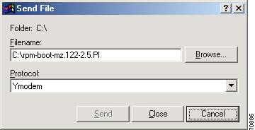
In the Filename box, browse and choose the image file to be downloaded. Also, since we used the "y" option while invoking the xmodem, set the transfer protocol to ymodem or use Xmodem protocol by not specifying the -y option on the command line.
The transfer screen comes up and transfer starts. (The transfer may not start immediately; wait for some time and it should start.)
After the transfer is completed (it should typically take about 10-15 minutes), the following messages are displayed on HyperTerminal console:
Returning console speed to 9600.Please reset your terminal emulator to this speed...Step 5
Usually, due to time lag between changing HyperTerminal speed back to 9600, you might see a bunch of garbage. To avoid this, disconnect and reconnect the HyperTerminal to get the console back again.
The system will reset itself from here and will boot with new software image.
Historical Information from the 1.2.x Baseline
Features Introduced in Release 1.2.02
Release 1.2.02 supports all new features introduced in the Release 1.2.0x baseline. (See "Historical Information from the 1.2.x Baseline" section.) The following is a new feature for RPM implementations using IOS Release 12.2(8)T1.
Configuring the Cellbus Clock (CBC) Rate
When two adjacent RPM cards are on the same cell bus, that is, occupy adjacent slots, the cellbus clock (CBC) rate should be set to 42MHz. If, for any reason, one of the adjacent RPMs goes to Failed or Empty state, the CBC must be reconfigured to 21MHz on the active, live RPM card, for Traffic Shaping to work correctly.
If the PXM puts one of the RPMs into failed state, while the RPM is functioning, the RPM must stop sending idle cells to avoid impacting traffic shaping on the remaining functional RPM.
CBC is enabled by default when the RPM is configured. Because it is enabled by default, the only commands necessary are:
rpm-auto-cbclk-change to stop the RPM from sending idle cells in the event of a failure by implementing an automatic cellbus clock change.
and
no rpm-auto-cbclk-change to keep the RPM from initiating an automatic cellbus clock change, when traffic shaping is not required.
The following screen output displays an example of the rpm-auto-cbclk-change command.
RPM-11#config terminalEnter configuration commands, one per line. End with CNTL/Z.RPM-11(config)#int sw1RPM-11(config-if)#rpm-auto-cbclk-changeRPM-11(config-if)#endRPM-11#write memBuilding configuration...[OK]RPM-11#show run int sw1Building configuration...Current configuration :142 bytes!interface Switch1no ip addressno atm ilmi-keepaliverpm-auto-cbclk-changeswitch autoSynch offend! rpm_tag_id Apr 04 2002 02:49:04RPM-11#config terminalEnter configuration commands, one per line. End with CNTL/Z.RPM-11(config)#int sw1RPM-11(config-if)#no rpm-auto-cbclk-changeRPM-11(config-if)#endRPM-11#write memBuilding configuration...[OK]RPM-11#show run int sw1Building configuration...Current configuration :145 bytes!interface Switch1no ip addressno atm ilmi-keepaliveno rpm-auto-cbclk-changeswitch autoSynch offend! rpm_tag_id Apr 04 2002 02:49:57If traffic shaping is not required, enter the no rpm-cbclk-change command, either manually or during card configuration. The following screen output displays an example of the no rpm-auto-cbclk-change command.
RPM-11#config terminalEnter configuration commands, one per line. End with CNTL/Z.RPM-11(config)#int sw1RPM-11(config-if)#no rpm-auto-cbclk-changeRPM-11(config-if)#endRPM-11#write memBuilding configuration...[OK]RPM-11#show run int sw1Building configuration...Current configuration :124 bytes!interface Switch1no ip addressno atm ilmi-keepaliveswitch autoSynch offend! rpm_tag_id Apr 04 2002 02:52:54After a reload, it would look like this:RPM-11#show run int sw1Building configuration...Current configuration :142 bytes!interface Switch1no ip addressno atm ilmi-keepaliverpm-auto-cbclk-changeswitch autoSynch offend! rpm_tag_id Apr 04 2002 02:55:03
Note
Features Introduced in Release 1.2.01
Release 1.2.01 is a feature release. The following table contains a short description of the new features that are available with Release 1.2.01.
Note
Standard ABR on FRSM-VHS Modules. This feature implements standard TM 4.0 ABR service on the FRSM-VHS card.
APS Support on SRM-E. The enhanced SRM-E Service Redundancy Module, which was introduced in Release 1.2.00, now provides GR.253 and ITU Annex-A and Annex-B APS 1+1 support.
Standard ABR on FRSM-VHS Modules
The feature implements TM 4.0 ABR service on the FRSM VHS cards which include FRSM-2CT3, FRSM-2T3E3, FRSM-HS2 and FRSM-HS2/B. The current FRSM supports a pre-standard version of congestion control- foresight. This feature provides standards compliant ABR congestion mechanism in addition to foresight. The module will generate RM cells to dynamically increase or decrease bandwidth rate. The scope involves to including all applicable modes of behavior Source, Destination or Switch. Only relevant modes need be considered. Connections with standard ABR parameter will be mapped to appropriate queues that also will co-exist with foresight connection types. For more information, refer to ForeSight and Standard ABR Coexistence Guidelines.
This feature will be implemented via appropriate MIBS and CLI. This feature is supported by CWM 10.5.10 patch 1. There will be one common license for foresight and standard ABR on FRSM. This is a billable feature. Standard ABR fulfills the standards compliance part of TM 4.0.
APS Support on SRM-E
The enhanced SRM-E Service Redundancy Module now provides GR.253 and ITU Annex-A and Annex-B APS 1+1 support. The SRM-E supports a new one-port OC3/STM1 back card, BERT, 1:N redundancy for the 8 port service modules and both T1 and E1 bulk distribution for the 8 port service modules. For more information on SRM-E, refer to SRM-E and CLI Modifications in 1.2.x Baseline.
For intercard APS to operate properly on the MGX 8850 and MGX 8250, an APS connector must be installed between the two cards. For more information on the APS connector and how to install it, see the Cisco MGX 8850 Routing Switch Hardware Installation Guide.
Note
Features Introduced in Release 1.2.00
Release 1.2.00 is a feature release. The following table contains a short description of the features which are available with Release 1.2.00.
FRSM-HS2/B. In addition to the current HSSI interface support, the new service module supports V.35 and X.21 Frame Relay interfaces.
SRM-E Service Redundancy Module is an enhanced version of the current SRM-3T3 card, supporting a new one-port OC3/STM1 back card. The new card supports BERT, 1:N redundancy for the 8 port service modules and both T1 and E1 bulk distribution for the 8 port service modules. APS support will be available in a future release.
ITU APS Annex-A, All Configurations Supported on PXM1. This feature was introduced in Release 1.1.40 with some configurations supported; now all are supported. Compatible with CWM 10.5 and higher.
CESM 8T1 Model B eliminates problem in DS0 throughput reduction when CESM channels are configured in CAS mode (not applicable for E1 lines).
PXM-UI-S3, provides support for Stratum-3 clocking. This card was first supported in Release 1.1.31. Release 1.1.31 was compatible with CWM 10.3. The upgrade to Release 1.2.00 provides important fixes to this feature.
FRSM-HS2/B
The FRSM-HS2/B service module supports v.35 and x.21 frame relay interfaces in addition to the current HSSI interface. A new 8 port back card 12IN1-8S is introduced. The new front card supports the current HSSI back card and the new 12IN1-8S back card. All the current FRSM-HS2 features are supported in addition to the FRSM-HS1/B features. Each interface in the 12IN1-8S can be individually configured as x.21 or v.35 interface. The new service module supports a maximum of 4000 connections with the 12IN1-8S back card and 2000 connections with the HSSI back card when no LMI is configured. When LMI is configured, the maximum number of connections per port for strataLMI port is 560 and Annex A/D UNI/NNI port is 898.
The FRSM-HS2/B supports both DCE and DTE modes with line rates between 48Kbps to 51.84 Mbps for HSSI interface and 48Kbps to 8.192 Mbps for v.35/x.21 interface. In FRSM-HS2B, for DTE interfaces the clock frequency threshold %ge is introduced and is configurable (1 - 5) % with a default value of 3%. The new front card and back card is supported in CWM 10.5.10.
Warning
A comparison of the FRSM-HS1/B, FRSM-HS2, and FRSM-HS2/B is shown in Table 9.
The following table lists the cables necessary for card performance.
SRM-E
The new Service Redundancy Module is an enhanced version of the current SRM-3T3 card. The new card supports a one-port OC3/STM1 back card or functions without a back card.
BERT
Bulk Distribution
1:N redundancy
BERT
--
1:N redundancy
The new card supports BERT, 1:N redundancy for the 8 port service modules and both T1 and E1 bulk distribution for the 8 port service modules. Support for both GR-253 and ITU- Annex A and B APS 1+1 will be provided in a future release.
The new front card will function without the back card for BERT and 1:N redundancy features. CWM and CiscoView will support the new front and back card.
You can have either 0, 2 or 4 SRM's with redundant processors and 0, 1 or 2 with non-redundant processors. The MGX8250 or MGX 8850 shelf has two bays while the MGX8230 has only one bay. Each bay of the MGX8x50 requires its own SRM-E card along with its respective back card. For full redundancy for the shelf, you need 4 SRM-Es and their respective back cards for MGX8850 or MGX 8250 switch (2 SRM-Es for MGX8230). Since the SRM-E is part of the core card set, if redundancy is required for the PXM, then redundancy also should be provided for the SRM-E.
SRM-E cards do not require any firmware to be downloaded to them. They are controlled by platform software running on the PXM. When a switch-over occurs from active PXM to standby PXM, the corresponding SRM-E cards (as part of the core card set) will also switch.
The interfaces available (through the appropriate back cards below) are:
· OC3 optical
· STS3 electrical
· STM1 optical
· STM1 electrical
The following cards are supported on both MGX8850 or MGX 8250 switch and the MGX8230 switch.SMFIR: Single Mode Intermediate Range Fiber
STM1-EL-1: Synchronous Transport Module level 1
ITU APS Annex-A, All Configurations Supported on PXM1
In the previous MGX1 release (1.1.40), limited ITU-APS Annex-A configuration was validated and made available in MGX 8230, 8250 and 8850 with support for a 1+1 bidirectional non-revertive configuration. In Release 1.2.00, the remaining configurations are supported.
CESM 8T1 Model B
CESM-8T1 and CESM-8E1 cards provide TDM circuit emulation capabilities over ATM networks, according to ATM forum CES-IS standards.
During field testing, it was found that in the case of CESM-8T1 cards (and not applicable for CESM-8E1 cards), when a CESM channel was configured in CAS mode, the first byte of an AAL1 structure may not be aligned to the first byte of T1 physical level multiframe (SF/ESF). This causes the effective DS0 throughput to reduce from 62.67 Kbps to 60 Kbps. This throughput reduction causes bit errors when the CESM-8T1 is used in certain kind of applications; for example, during transfers of modem calls.
Both hardware and firmware changes were required to eliminate this anomaly. The hardware changes are implemented as CESM-8T1/B revision of the hardware with a minimum Firmware Release 1.2.00. No earlier versions of firmware are supported. The model "B" does not show up via CLI on the PXM or via CWM. However, if the command dspcd is executed from the CESM Model B, it will display "CESM8T1B" next to the Fab number. This can be used to differentiate between CESM model A and B cards. The CESM8T1/B card also is identified by a new face plate on which the card name is suffixed with a "B.".
Model A and Model B card are interchangeable, except when multi-framing is enabled on Model-B. In that case, multi-framing must be disabled before changing cards. Note that the default framing mode is non-multiframe (in order to have a compatibility between Model-A & Model-B).
The CESM8T1/B card supports 1:N redundancy.
PXM-UI-S3
Standard clocking in the MGX is supported with a built-in Stratum-4 clock source. For network applications that require a higher clock accuracy, the PXM-UI back card used with the Stratum-4 can be replaced with an optional PXM-UI-S3 back card that carries a Stratum-3 clock. This clock reference conforms to AT&T T1.5 and ITU G.824 specifications. A provision is also made for a Service Provider to connect an external clock source, if necessary.
The default clock is the internal Stratum-4. Pertinent CLI and MIB support are provided for Stratum-3 configuration. The PXM-UI-S3 back card is also recognized by the Cisco WAN Manager.
The Stratum-3 Clocking feature on the PXM-UI-S3 was introduced in Release 1.1.31, but support was removed in subsequent releases. It is being supported again in Release 1.2.00 and higher.
Hardware Changes
The new PXM-UI-S3 supports both T1 and E1 interfaces through an RJ-45/48 connector.
CLI
A new CLI cnfclklevel permits the user to set the STRATUM level desired.
Default Settings
VISM Release 2.2 on MGX 8250, MGX 8850 Release 1, and MGX8230 Switches supported on the PXM-UI-S3 or this release. The external clock interface cannot be used for Stratum 4 with UIS3 backcard.
Warning
* cnfclklevel 3
* cnfextclk (with T1/E1 option)
Problems Fixed in Release 1.2.02
The following is the list of problems fixed in the service module firmware and the Release 1.2.02 software. Included with each is a brief discussion of the problem. A more in-depth discussion is available in the Release Note enclosure of the problem record in Bug Navigator.
Problems Fixed in Release 1.2.01
The following is the list of problems fixed in the service module firmware and the Release 1.2.01 software. Included with each is a brief discussion of the problem. A more in-depth discussion is available in the Release Note enclosure of the problem record in Bug Navigator.
Note
Problems Fixed in Release 1.2.00
The following is the list of problems fixed in the service module firmware and the Release 1.2.00 software. Included with each is a brief discussion of the problem. A more in-depth discussion is available in the Release Note enclosure of the problem record in Bug Navigator.
Related Documentation
Note that for Release 1.2.00, the product documents (Command Reference, Overview, and Installation and Configuration Guides) were not updated. Use the Release 1.1.3 documents in addition to the Release Notes for Cisco WAN MGX 8850, MGX 8230, and MGX 8250 Software Version 1.2.00.
Product documentation for MGX 8850 is available at the following URL:
http://www.cisco.com/univercd/cc/td/doc/product/wanbu/mgx8850/1_1_31/index.htmProduct documentation for MGX 8230 is available at the following URL: http://www.cisco.com/univercd/cc/td/doc/product/wanbu/mgx8230/1_1_31/index.htm
Product documentation for MGX 8250 is available at the following URL:
http://www.cisco.com/univercd/cc/td/doc/product/wanbu/mgx8250/1_1_31/index.htmProduct documentation for VISM 2.2 is available at the following URL:
http://www.cisco.com/univercd/cc/td/doc/product/wanbu/mgx8850/vism22
http://www.cisco.com/univercd/cc/td/doc/product/wanbu/mgx8250/vism22
http://www.cisco.com/univercd/cc/td/doc/product/wanbu/mgx8230/vism22If you are reading Cisco product documentation on the World Wide Web, you can submit comments electronically. Follow the instructions at the top of the documentation page, prompting you to "Click here" to link to the Documentation Survey form. After you complete the form, click Submit to send it to Cisco. We appreciate your comments.
Obtaining Documentation
The following sections explain how to obtain documentation from Cisco Systems.
World Wide Web
You can access the most current Cisco documentation on the World Wide Web at the following URL:
Translated documentation is available at the following URL:
http://www.cisco.com/public/countries_languages.shtml
Documentation CD-ROM
Cisco documentation and additional literature are available in a Cisco Documentation CD-ROM package, which is shipped with your product. The Documentation CD-ROM is updated monthly and may be more current than printed documentation. The CD-ROM package is available as a single unit or through an annual subscription.
Ordering Documentation
Cisco documentation is available in the following ways:
•
http://www.cisco.com/cgi-bin/order/order_root.pl
•
http://www.cisco.com/go/subscription
•
Documentation Feedback
If you are reading Cisco product documentation on Cisco.com, you can submit technical comments electronically. Click Leave Feedback at the bottom of the Cisco Documentation home page. After you complete the form, print it out and fax it to Cisco at 408 527-0730.
You can e-mail your comments to bug-doc@cisco.com.
To submit your comments by mail, use the response card behind the front cover of your document, or write to the following address:
Cisco Systems
Attn: Document Resource Connection
170 West Tasman Drive
San Jose, CA 95134-9883We appreciate your comments.
Obtaining Technical Assistance
Cisco provides Cisco.com as a starting point for all technical assistance. Customers and partners can obtain documentation, troubleshooting tips, and sample configurations from online tools by using the Cisco Technical Assistance Center (TAC) Web Site. Cisco.com registered users have complete access to the technical support resources on the Cisco TAC Web Site.
Cisco.com
Cisco.com is the foundation of a suite of interactive, networked services that provides immediate, open access to Cisco information, networking solutions, services, programs, and resources at any time, from anywhere in the world.
Cisco.com is a highly integrated Internet application and a powerful, easy-to-use tool that provides a broad range of features and services to help you to
•
•
•
•
•
You can self-register on Cisco.com to obtain customized information and service. To access Cisco.com, go to the following URL:
Technical Assistance Center
The Cisco TAC is available to all customers who need technical assistance with a Cisco product, technology, or solution. Two types of support are available through the Cisco TAC: the Cisco TAC Web Site and the Cisco TAC Escalation Center.
Inquiries to Cisco TAC are categorized according to the urgency of the issue:
•
•
•
•
Which Cisco TAC resource you choose is based on the priority of the problem and the conditions of service contracts, when applicable.
Cisco TAC Web Site
The Cisco TAC Web Site allows you to resolve P3 and P4 issues yourself, saving both cost and time. The site provides around-the-clock access to online tools, knowledge bases, and software. To access the Cisco TAC Web Site, go to the following URL:
All customers, partners, and resellers who have a valid Cisco services contract have complete access to the technical support resources on the Cisco TAC Web Site. The Cisco TAC Web Site requires a Cisco.com login ID and password. If you have a valid service contract but do not have a login ID or password, go to the following URL to register:
http://www.cisco.com/register/
If you cannot resolve your technical issues by using the Cisco TAC Web Site, and you are a Cisco.com registered user, you can open a case online by using the TAC Case Open tool at the following URL:
http://www.cisco.com/tac/caseopen
If you have Internet access, it is recommended that you open P3 and P4 cases through the Cisco TAC Web Site.
Cisco TAC Escalation Center
The Cisco TAC Escalation Center addresses issues that are classified as priority level 1 or priority level 2; these classifications are assigned when severe network degradation significantly impacts business operations. When you contact the TAC Escalation Center with a P1 or P2 problem, a Cisco TAC engineer will automatically open a case.
To obtain a directory of toll-free Cisco TAC telephone numbers for your country, go to the following URL:
http://www.cisco.com/warp/public/687/Directory/DirTAC.shtml
Before calling, please check with your network operations center to determine the level of Cisco support services to which your company is entitled; for example, SMARTnet, SMARTnet Onsite, or Network Supported Accounts (NSA). In addition, please have available your service agreement number and your product serial number.
This document is to be used in conjunction with the Cisco WAN Switching MGX 8850 Release 1, MGX 8250, and MGX 8230 publications.
Copyright © 2002, Cisco Systems, Inc.
All rights reserved.