Catalyst 6500 Ethernet Module Installation Guide
Bias-Free Language
The documentation set for this product strives to use bias-free language. For the purposes of this documentation set, bias-free is defined as language that does not imply discrimination based on age, disability, gender, racial identity, ethnic identity, sexual orientation, socioeconomic status, and intersectionality. Exceptions may be present in the documentation due to language that is hardcoded in the user interfaces of the product software, language used based on RFP documentation, or language that is used by a referenced third-party product. Learn more about how Cisco is using Inclusive Language.
- Updated:
- August 26, 2012
Chapter: Pluggable Transceivers
Pluggable Transceiver Modules
This appendix provides descriptions and specifications for the pluggable transceiver modules that are supported on the Catalyst 6500 series Ethernet switching modules.
The appendix is divided into these topics:
100-MB Transceivers
100-MB small form-factor pluggable (SFP) transceivers are currently the only 100-MB transceivers that are supported on a Catalyst 6500 series Ethernet switching module. They are supported only on the WS-X6148-FE-SFP Ethernet module.
The 100-MB SFP transceiver module is shown in Figure B-1. Table B-1 lists the types of 100-MB SFP transceivers and their cabling distances.

Note ![]() The 100-MB and the 1-GB SFP transceivers share the same form factor, but are not interchangeable.
The 100-MB and the 1-GB SFP transceivers share the same form factor, but are not interchangeable.
Figure B-1 100-MB SFP Transceiver Module

|
|
|
|
(nm) |
|
|
|
|---|---|---|---|---|---|---|
GLC-FE-100FX |
100BASE-FX SFP for 100 Mb (Fast Ethernet) ports |
Dual LC |
1310 |
MMF |
50/62.5 |
1.24 miles (2 km) |
GLC-FE-100LX |
100BASE-LX10 SFP for 100 Mb (Fast Ethernet) ports |
Dual LC |
1310 |
SMF |
G.6523 |
6.21 miles (10 km) |
GLC-FE-100BX-D |
100BASE-FX SFP for 100 Mb (Fast Ethernet) ports |
Single LC |
1550 (receive) 1310 (transmit) |
Single-strand SMF |
G.6523 |
6.21 miles (10 km) |
GLC-FE-100BX-U |
100BASE-FX SFP for 100 Mb (Fast Ethernet) ports |
Single LC |
1310 (receive) 1550 (transmit) |
Single-strand SMF |
G.6523 |
6.21 miles (10 km) |
GLC-FE-100EX |
100BASE-EX for 100 Mb (Fast Ethernet) ports |
Dual LC |
1310 |
SMF |
G.6523 |
24.86 miles (40 km) |
GLC-FE-100ZX |
100BASE-ZX for 100 Mb (Fast Ethernet) ports |
Dual LC |
1550 |
SMF |
G.6523 |
49.7 miles (80 km) |
1 The numbers given for multimode fiber-optic (MMF) cable refer to the core diameter. 2 Cable distances are based on fiber loss. Additional factors, such as the number of splices and the optical quality of the fiber, can affect cabling distances. 3 ITU-T G.652 SMF as specified by the IEEE 802.3z standard. |
Note ![]() The minimum cable distance for all 100-MB SFP transceivers listed, both MMF and SMF (G.652), is 6.5 feet (2 meters).
The minimum cable distance for all 100-MB SFP transceivers listed, both MMF and SMF (G.652), is 6.5 feet (2 meters).
Table B-2 lists the fiber loss budgets for the 100-MB SFP transceivers.
Table B-3 lists the physical and environmental specifications for the 100-MB SFP transceivers.
1-GB Transceivers
The 1-GB transceivers include the Gigabit Interface Converter (GBIC) transceiver and the SFP transceiver. The GBIC transceivers and SFP transceivers differ in both form-factor and in connector type; they are not interchangeable. Table B-4 lists the 1-GB transceiver types, the modules that support them, the transceiver illustrations, and the specification tables.
|
|
|
|
|
|---|---|---|---|
GBIC |
• • • • • |
Figure B-2 (1000BASE-T copper GBIC) Figure B-3 (1000BASE-X optical GBIC) |
Table B-5 (cabling specifications) Table B-6 (fiber loss budgets) Table B-7 (environmental specifications) |
SFP |
• • • • |
Figure B-4 (1000BASE-T copper SFP) Figure B-5 (1000BASE-X optical SFP) |
Table B-8 (cabling specifications) Table B-9 (fiber loss budgets) Table B-10 (environmental specifications) |
1 Not all GBIC transceiver types or SFP transceiver types may be supported on your module. Refer to your software release notes to determine if a specific GBIC transceiver or SFP transceiver is supported on your module. |
1-GB GBIC Transceivers
Figure B-2 shows a 1000BASE-T (copper) GBIC transceiver. Figure B-3 shows a 1000BASE-X (optical) GBIC transceiver. Table B-5 lists the cabling specifications for the GBIC transceivers.
Figure B-2 1000BASE-T GBIC Transceiver (WS-G5483)
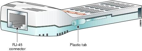
Figure B-3 1000BASE-X GBIC Transceiver Modules (WS-G5484, WS-G5486, and WS-G5487)
|
|
|
(nm) |
|
|
(MHz km) |
|
|---|---|---|---|---|---|---|
1000BASE-T |
RJ-45 |
— |
— |
— |
328 ft (100 m) |
|
1000BASE-SX3 |
SC duplex |
850 |
MMF |
62.5 62.5 50.0 50.0 |
160 200 400 500 |
722 ft (220 m) 902 ft (275 m) 1640 ft (500 m) 1804 ft (550 m) |
1000BASE-LX/LH |
SC duplex |
1310 |
MMF4 SMF |
62.5 50.0 50.0 G.6525 |
500 400 500 — |
1804 ft (550 m) 1804 ft (550 m) 1804 ft (550 m) 6.2 mi (10 km) |
1000BASE-ZX6 |
SC duplex |
1550 |
SMF SMF7 |
G.6525 G.6525 |
— — |
43.5 mi (70 km)8 62.1 mi (100 km) |
1 The numbers given for multimode fiber-optic (MMF) cable refer to the core diameter. 2 Cable distances are based on fiber loss. Additional factors, such as the number of splices and the optical quality of the fiber, can affect cabling distances. 3 Use with MMF only. 4 Refer to the product bulletin for the usage of mode conditioning patch cords in 1000BASE and 10GBASE Ethernet laser-based transmissions at this URL: http://www.cisco.com/en/US/prod/collateral/modules/ps5455/product_bulletin_c25-530836.html 5 ITU-T G.652 SMF as specified by the IEEE 802.3z standard. 6 Use with SMF only. 7 Dispersion-shifted single-mode fiber-optic cable. 8 The minimum link distance for ZX GBICs is 6.2 miles (10 km), when an 8-dB attenuator is installed at each end of the link. Without attenuators, the minimum link distance is 24.9 miles (40 km). |
Table B-6 lists the fiber loss budgets for the GBIC transceivers.
|
|
|
|
|---|---|---|
WS-G5484 (1000BASE-SX) |
-3 (maximum) -9.5 (minimum) |
0 (maximum) -17 (minimum) |
WS-G5486 (1000BASE-LX/LH) |
-3 (maximum) -9.5 (minimum) |
-3 (maximum) -19 (minimum) |
WS-G5487 (1000BASE-ZX) |
5 (maximum) 0 (minimum) |
-3 (maximum) -23 (minimum)1 |
1 The 1000BASE-ZX GBIC transceiver provides a minimum optical power budget of 23 dB. To determine the supported link distance, you need to measure your cable plant with an optical loss test set to verify that the optical loss of the cable plant (including connectors and splices) is less than or equal to this value. The optical measurement must be performed with a 1550 nanometer light source. |
Table B-7 lists the physical and environmental specifications for the GBIC transceivers.
1-GB SFP Transceivers
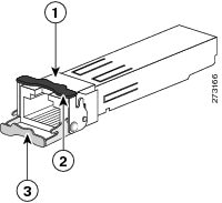
Figure B-4 shows a 1000BASE-T (copper) SFP transceiver. Figure B-5 shows a 1000BASE-X (optical) SFP transceiver. Table B-8 lists the cabling specifications for the GBIC transceivers.
Figure B-4 1000BASE-T SFP Transceiver (GLC-T)
|
|
RJ-45 connector |
|
Bale-clasp shown in the open (unlocked) position |
|
|
Bale-clasp shown in the closed (locked) position |
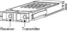
Figure B-5 1000BASE-X SFP Transceivers
|
|
|
|
|
|
|
|
|---|---|---|---|---|---|---|
1000BASE-T |
RJ-45 |
— |
Category 5, 5e, or 6 UTP/FTP |
— |
— |
328 ft (100 m) |
1000BASE-SX |
LC duplex |
850 |
MMF |
62.5 |
160 |
722 ft (220 m) |
1000BASE-LX/LH |
LC duplex |
1300 |
MMF2 |
62.5 |
500 |
1804 ft (550 m) |
1000BASE-ZX |
LC duplex |
1550 |
SMF |
G.6523 |
— |
43.4 to 62 mi (70 to 100 km)4 |
1 Cable distances are based on fiber loss. Additional factors, such as the number of splices and the optical quality of the fiber, can affect cabling distances. 2 Refer to the product bulletin for the usage of mode conditioning patch cords in 1000BASE and 10GBASE Ethernet laser-based transmissions at this URL: http://www.cisco.com/en/US/prod/collateral/modules/ps5455/product_bulletin_c25-530836.html 3 ITU-T G.652 SMF as specified by the IEEE 802.3z standard. 4 1000BASE-ZX SFP modules can reach up to 62 miles (100 km) by using dispersion-shifted SMF or low-attenuation SMF; the actual distance depends on the fiber quality, the number of splices, and the connectors. |
Table B-9 lists the fiber loss budgets for the 1-GB SFP transceivers.
Table B-10 lists the physical and environmental specifications for the 1-GB SFP transceivers.
Note ![]() You can use any combination of SFP modules that your Cisco device supports. The only restrictions are that each SFP port must match the wavelength specifications on the other end of the cable and that the cable must not exceed the stipulated cable length for reliable communications.
You can use any combination of SFP modules that your Cisco device supports. The only restrictions are that each SFP port must match the wavelength specifications on the other end of the cable and that the cable must not exceed the stipulated cable length for reliable communications.
10-GB Transceivers
The 10-GB transceiver types include the XENPAK transceiver and the X2 transceiver. The XENPAK transceivers and X2 transceivers differ in form-factor; they are not interchangeable. Table B-11 lists both 10-GB transceiver types and the modules that support them
|
|
|
|---|---|
XENPAK transceivers |
• • |
X2 transceivers |
• • • • • • |
SFP+ transceivers |
• • • |
1 Not all 10-GB transceiver versions may be supported on your module. Refer to your software release notes to determine if a specific 10-GB transceiver is supported on your module. 2 The VS-S720-10G-3C and the VS-S720-10G-3CXL supervisor engines have two 10-Gigabit transceiver uplink ports on the front panel. Normally, the ports support X2 transceivers. By using a OneX converter, the 10-Gigabit port can also support SFP+ transceivers 3 The WS-X6904-40G Ethernet module has four ports that support 40-Gigabit CFP transceivers. By installing a FourX converter in a port, that port can accept up to four SFP+ transceivers. |
XENPAK Transceivers
XENPAK transceivers are supported in the WS-X6704-10GE 10-Gigabit Ethernet module. Figure B-6 shows the form-factor of the XENPAK transceiver. Table B-12 lists the optical and the cabling distance specifications for the XENPAK transceivers.
Note ![]() The dual SC connector on the X2 transceivers support network interface cables with either Physical Contact (PC) or Ultra-Physical Contact (UPC) polished face types. The connectors do not support network interface cables with an Angle Polished Connector (APC)-polished face type.
The dual SC connector on the X2 transceivers support network interface cables with either Physical Contact (PC) or Ultra-Physical Contact (UPC) polished face types. The connectors do not support network interface cables with an Angle Polished Connector (APC)-polished face type.
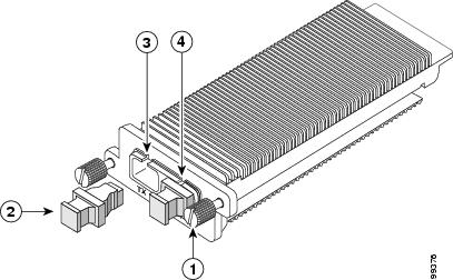
Figure B-6 10-Gigabit XENPACK Transceiver
|
|
Captive installation screw |
|
Transmit optical bore |
|
|
Optical bore dust plug |
|
Receive optical bore |
|
|
|
|
|
|
|
Distance 1 |
|---|---|---|---|---|---|---|
XENPAK-10GB-CX4 |
InfiniBand 4X |
N/A |
CX4 (copper) |
— |
— |
49 ft (15 m)2 |
XENPAK-10GB-SR |
SC duplex |
850 nm |
MMF |
62.5 62.5 50.0 50.0 50.0 |
160 200 400 500 2000 |
85.3 ft (26 m) 108.3 ft (33 m) 216.5 ft (66 m) 269.0 ft (82 m) 984.3 ft (300 m) |
XENPAK-10GB-LX4 |
SC duplex |
1310 nm |
MMF |
62.5 50.0 50.0 |
500 400 500 |
984.3 ft (300 m)3 787.4 ft (240 m) 984.3 ft (300 m) |
XENPAK-10GB-LR XENPAK-10GB-LR+ |
SC duplex |
1310 nm |
SMF |
G.6524 |
— |
6.2 mi (10 km) |
XENPAK-10GB-LRM |
SC duplex |
1310 nm |
MMF |
62.5 50.0 50.0 |
500 400 500 |
722 ft (220 m)5 328 ft (100 m) 722 ft (220 m) |
XENPAK-10GB-LW6 |
SC duplex |
1310 nm |
SMF |
G.6522 |
— |
6.21 mi (10 km) |
XENPAK-10GB-ER7 XENPAK-10GB-ER+7 |
SC duplex |
1550 nm |
SMF |
G.6524 |
— |
24.9 mi (40 km) |
XENPAK-10GB-ZR |
SC duplex |
1550 nm |
SMF |
— |
— |
50 mi (80 km) |
1 Cable distances are based on fiber loss. Additional factors, such as the number of splices and the optical quality of the fiber, can affect cabling distances. The minimum cabling distance for optical XENPAK types (LX4, SR, LR, and ER) is 6.6 ft (2 m) according to the IEEE 802.3ae standard. The minimum cabling distance for the XENPAK-10GB-LRM is 1.6 ft (0.5 m) according to IEEE 802.3aq standard. 2 The Cisco XENPAK-10GB-CX4 transceiver supports link lengths of up to 49.2 feet (15 m) on CX4 cable. Cisco offers four CX4 cables: CAB-INF-28G-1= (1 meter cable), CAB-INF-28G-5= (5 meter cable), CAB-INF-28G-10= (10 meter cable), and CAB-INF-26G-15= (15 meter cable). 3 The Cisco XENPAK-10GB-LX4 transceiver supports link lengths of 300 meters on standard Fiber Distributed Data Interface (FDDI) grade multimode fiber (MMF). To ensure that specifications are met, the transmitter output should be coupled through a mode conditioning patch cord. Cisco offers two mode conditioning patch cords: CAB-GELX-625= (mode conditioning patch cable, 62.5 microns, dual SC connectors) and CAB-MCP50-SC= (mode conditioning patch cable, 50 microns, dual SC connectors). 4 ITU-T G.652 SMF as specified by the IEEE 802.3z standard. Even though dispersion-shifted optical fiber reduces signal dispersion, which allows the signal to travel farther, signal attenuation still limits its distance. 5 The Cisco XENPAK-10GB-LRM transceiver supports link lengths of 220m on standard Fiber Distributed Data Interface (FDDI) grade multimode fiber (MMF). To ensure that specifications are met over FDDI-grade, OM1 and OM2 fibers, the transmitter should be coupled through a mode conditioning patch cord. Cisco offers two mode conditioning patch cords: CAB-GELX-625= (mode conditioning patch cable 62.5 microns, dual SC connectors) and CAB-MCP50-SC= (mode conditioning patch cable 50 microns, dual SC connectors). No mode conditioning patch cord is required for applications using OM3. 6 The XENPAK-10GB-LW (WAN PHY) supports a link length of 6.2 miles (10 km) on standard SMF (G.652). 7 Requires a 5 db 1550 nm fixed loss attenuator for cable distances less than 12.43 miles (20 km). The attenuator is available from Cisco Systems |
Table B-13 lists the fiber loss budgets for the 10-GB XENPAK transceivers.
|
|
|
|
|---|---|---|
XENPAK-10GB-SR |
-1.21 (maximum) -7.3 (minimum) |
-1 (maximum) -9.9 (minimum) |
XENPAK-10GB-LX4 |
-0.5 per lane (maximum) -6.75 per lane (minimum) |
-0.5 per lane (maximum) -14.25 per lane (minimum) |
XENPAK-10GB-LR XENPAK-10GB-LR+ |
0.5 (maximum) -8.2 (minimum) |
0.5 (maximum) -14.4 (minimum) |
XENPAK-10GB-LRM |
0.5 (maximum) -6.5 (minimum) |
0.5 (maximum) -8.4 (minimum) (in average) 6.4 (minimum) (in Optical Modulation Amplitude (OMA))2 |
XENPAK-10GB-LW |
0.5 (maximum) -8.2(minimum) |
0.5 (maximum) -14.4 (minimum) |
XENPAK-10GB-ER XENPAK-10GB-ER+ |
4.0 (maximum) -4.7 (minimum) |
-1.0 (maximum) -15.8 (minimum) |
XENPAK-10GB-ZR |
4.0 (maximum) 0 (minimum) |
-7.0 (maximum) -24.0 (minimum) |
1 The launch power shall be the lesser of the class 1 safety limit or the maximum receive power. Class 1 laser requirements are defined by IEC 60825-1: 2001. 2 Both the average and the OMA specifications must be met simultaneously. |
Table B-14 lists the physical and environmental specifications for the XENPAK transceivers.
X2 Transceivers
X2 transceivers are supported on the WS-X6708-10GE, WS-X6716-10GE, and the WS-X6848-10GE 10-Gigabit Ethernet modules. Not all X2 transceiver types are supported unconditionally by these two modules; the following caveats apply:
•![]() X2-10GB-CX4—10GBASE for CX4 (copper) cable. No restrictions for use.
X2-10GB-CX4—10GBASE for CX4 (copper) cable. No restrictions for use.
•![]() X2-10GB-ER—10GBASE-ER serial 1550-nm extended-reach, single-mode fiber (SMF), dispersion-shifted fiber (DSF). X2-10GB-ER transceivers labeled with a serial number that ends in -02 do not provide EMI compliance with the WS-X6716-10GE module. (See Figure B-7 for the serial number location.)
X2-10GB-ER—10GBASE-ER serial 1550-nm extended-reach, single-mode fiber (SMF), dispersion-shifted fiber (DSF). X2-10GB-ER transceivers labeled with a serial number that ends in -02 do not provide EMI compliance with the WS-X6716-10GE module. (See Figure B-7 for the serial number location.)
•![]() X2-10GB-LR—10GBASE-LR serial 1310-nm long-reach, single-mode fiber (SMF), dispersion-shifted fiber (DSF). X2-10GB-LR transceivers labeled with a serial number that ends in -02 do not provide EMI compliance with the WS-X6716-10GE module. (See Figure B-7 for the serial number location.)
X2-10GB-LR—10GBASE-LR serial 1310-nm long-reach, single-mode fiber (SMF), dispersion-shifted fiber (DSF). X2-10GB-LR transceivers labeled with a serial number that ends in -02 do not provide EMI compliance with the WS-X6716-10GE module. (See Figure B-7 for the serial number location.)
•![]() X2-10GB-LRM—10GBASE-LRM for FDDI-grade multimode fiber (MMF). The X2-10GB-LRM is not supported by the show idprom command.
X2-10GB-LRM—10GBASE-LRM for FDDI-grade multimode fiber (MMF). The X2-10GB-LRM is not supported by the show idprom command.
•![]() X2-10GB-LX4—10GBASE-LX4 serial 1310-nm multimode fiber (MMF). X2-10GB-LX4 transceivers that are labeled with a serial number that ends with -01, -02, or -03 do not provide EMI compliance when they are installed in the WS-X6716-10GE. (See Figure B-7 for the serial number location.)
X2-10GB-LX4—10GBASE-LX4 serial 1310-nm multimode fiber (MMF). X2-10GB-LX4 transceivers that are labeled with a serial number that ends with -01, -02, or -03 do not provide EMI compliance when they are installed in the WS-X6716-10GE. (See Figure B-7 for the serial number location.)
•![]() X2-10GB-SR—10GBASE-SR serial 850-nm short-reach multimode fiber (MMF). No restrictions for use.
X2-10GB-SR—10GBASE-SR serial 850-nm short-reach multimode fiber (MMF). No restrictions for use.
Figure B-7 X2 Transceiver Serial Number Label Locator
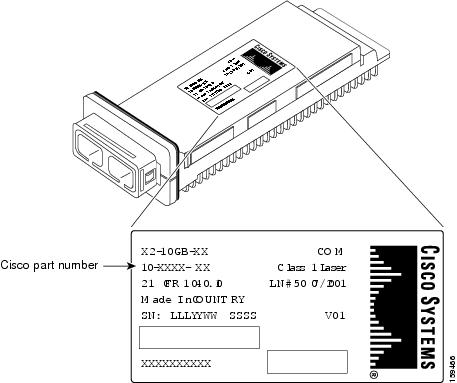
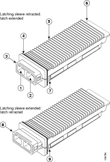
Figure B-8 shows the X2 transceivers with the major features identified. Table B-15 lists the cabling specifications for the X2 transceivers.
Figure B-8 10-GB X2 Transceiver
|
|
|
|
|
|
|
|
|---|---|---|---|---|---|---|
X2-10GB-CX4 |
InfiniBand 4X |
— |
InfiniBand (copper) |
— |
— |
49.2 ft (15 m)2 |
X2-10GB-SR |
SC duplex |
850 |
MMF |
62.5 62.5 50.0 50.0 50.0 |
160 200 400 500 2000 |
85.3 ft (26 m) 108.3 ft (33 m) 216.5 ft (66 m) 269 ft (82 m) 984.3 ft (300 m) |
X2-10GB-LX4 |
SC duplex |
1310 |
MMF |
62.5 50.0 50.0 |
500 400 500 |
984.3 ft (300 m)3 787.4 ft (240 m) 984.3 ft (300 m) |
X2-10GB-LR |
SC duplex |
1310 |
SMF |
G.652 fiber |
— |
6.21 mi (10 km) |
X2-10GB-LRM |
SC duplex |
1310 |
MMF |
62.5 50.0 50.0 |
500 400 500 |
722 ft (220 m)4 328 ft (100 m) 722 ft (220 m) |
X2-10GB-ER5 |
SC duplex |
1550 |
SMF |
G.652 fiber |
— |
24.84 mi (40 km) |
1 Cable distances are based on fiber loss. Additional factors, such as the number of splices and the optical quality of the fiber, can affect cabling distances. The minimum cabling distance for optical X2 transceiver types (LX4, SR, LR, and ER) is 6.6 ft (2 m) according to the IEEE 802.3ae standard. The minimum cabling distance for the X2-10GB-LRM is 1.6 ft (0.5 m) according to IEEE 802.3aq standard. 2 The Cisco X2-10GB-CX4 transceiver supports link lengths of up to 49.2 feet (15 m) on CX4 cable. Cisco offers four CX4 cables: CAB-INF-28G-1= (1 meter cable), CAB-INF-28G-5= (5 meter cable), CAB-INF-28G-10= (10 meter cable), and CAB-INF-26G-15= (15 meter cable). 3 The Cisco X2-10GB-LX4 transceiver supports link lengths of 300 meters on standard Fiber Distributed Data Interface (FDDI) grade multimode fiber (MMF). To ensure that specifications are met, the transmitter output should be coupled through a mode conditioning patch cord. Cisco offers two mode conditioning patch cords: CAB-GELX-625= (mode conditioning patch cable, 62.5 microns, dual SC connectors) and CAB-MCP50-SC= (mode conditioning patch cable, 50 microns, dual SC connectors). 4 The Cisco X2-10GB-LRM transceiver supports link lengths of 220 meters on standard Fiber Distributed Data Interface (FDDI) grade multimode fiber (MMF). To ensure that specifications are met over FDDI-grade, OM1 and OM2 fibers, the transmitter should be coupled through a mode conditioning patch cord. Cisco offers two mode conditioning patch cords: CAB-GELX-625= (mode conditioning patch cable 62.5 microns, dual SC connectors) and CAB-MCP50-SC= (mode conditioning patch cable 50 microns, dual SC connectors). No mode conditioning patch cord is required for applications using OM3. 5 Requires a 5 db 1550 nm fixed loss attenuator for cable distances less than 12.43 miles (20 km). The attenuator is available from Cisco Systems |
Table B-16 lists the fiber loss budgets for the 10-GB X2 transceivers.
|
|
|
|
|---|---|---|
X2-10GB-LRM |
0.5 (max) -6.5 (min) |
0.5 (max) -8.4 (min) (In average)1 -6.4 (min) (in Optical Modulation Amplitude (OMA)) |
X2-10GB-SR |
-1.2 (max)2 -7.3 (min) |
-1.0 (max) -9.9 (min) |
X2-10GB-LR |
0.5 (max) -8.2 (min) |
0.5 (max) -14.4 (min) |
X2-10GB-ER |
4.0 (max) -4.7 (min) |
-1.0 (max) -15.8 (min) |
X2-10GB-LX4 |
-0.5 per lane (max) -6.75 per lane |
-0.5 (max) -14.4 per lane |
1 Both the average and the OMA specifications must be met simultaneously. 2 The launch power shall be the lesser of the class 1 safety limit or the maximum receive power. Class 1 laser requirements are defined by IEC 60825: 2001. |
Table B-17 lists the physical and environmental specifications for the X2 transceiver.
SFP+ Transceivers
10-Gigabit SFP+ transceivers are supported by the Virtual Switching Supervisor Engine 720 (VS-S720-10G-3C and VS-S720-10G-3CXL) and the WS-X6904-40G Ethernet module (with the use of FourX converter modules). The supervisor engine has two 10-Gigabit ports on the the front panel. The two ports normally accepts X2 10-Gigabit transceivers. By installing a OneX converter module (CVR-X2-SFP10G) in the port, the port can accept a 10-Gigabit SFP+ transceiver. For general information, compatibility matrix, and installation instructions for the SFP+ transceiver, see the following publications:
•![]() For general information on the 10-Gigabit SFP+ transceiver modules including models and specifications, see the Cisco 10GBASE SFP+ Modules Data Sheet at the following URL:
For general information on the 10-Gigabit SFP+ transceiver modules including models and specifications, see the Cisco 10GBASE SFP+ Modules Data Sheet at the following URL:
http://www.cisco.com/en/US/prod/collateral/modules/ps5455/data_sheet_c78-455693.html
•![]() For details on which modules support the 10-Gigabit SFP+ transceiver module and software requirements, see the Cisco 10-Gigabit Ethernet Transceiver Modules Compatibility Matrix at the following URL:
For details on which modules support the 10-Gigabit SFP+ transceiver module and software requirements, see the Cisco 10-Gigabit Ethernet Transceiver Modules Compatibility Matrix at the following URL:
•![]() For 10-Gigabit SFP+ transceiver installation instructions, see the Cisco SFP and SFP+ Transceiver Module Installation Notes at the following URL:
For 10-Gigabit SFP+ transceiver installation instructions, see the Cisco SFP and SFP+ Transceiver Module Installation Notes at the following URL:
•![]() For general information on the OneX converter, see the Cisco OneX Converter Module data sheet at the following URL:
For general information on the OneX converter, see the Cisco OneX Converter Module data sheet at the following URL:
•![]() http://www.cisco.com/en/US/prod/collateral/modules/ps5455/data_sheet_c78-547521.html
http://www.cisco.com/en/US/prod/collateral/modules/ps5455/data_sheet_c78-547521.html
40-Gigabit Transceivers
40-Gigabit CFP transceivers are supported by the WS-X6904-40G Ethernet module. The module accepts up to four of the 40-Gigabit CFP transceivers in slots on the module front panel. For general information, compatibility matrix, and installation instructions, see the following publications:
•![]() For general information, including specifications and optical characteristics, on the 40-Gigabit CFP transceiver modules, see the Cisco 40GBASE CFP Modules Data Sheet at the following URL:
For general information, including specifications and optical characteristics, on the 40-Gigabit CFP transceiver modules, see the Cisco 40GBASE CFP Modules Data Sheet at the following URL:
http://www.cisco.com/en/US/prod/collateral/modules/ps5455/data_sheet_c78-702617.html
•![]() For 40-Gigabit CFP transceiver module compatibility information, see the Cisco 40-Gigabit Ethernet Transceiver Modules Compatibility Matrix at the following URL:
For 40-Gigabit CFP transceiver module compatibility information, see the Cisco 40-Gigabit Ethernet Transceiver Modules Compatibility Matrix at the following URL:
•![]() For 40-Gigabit CFP transceiver module installation instructions, see the Cisco 40-Gigabit and 100-Gigabit CFP transceiver Modules Installation Note at the following URL:
For 40-Gigabit CFP transceiver module installation instructions, see the Cisco 40-Gigabit and 100-Gigabit CFP transceiver Modules Installation Note at the following URL:
WDM Transceivers
The WDM transceiver modules are listed in Table B-18 along with brief descriptions of the transceiver modules and illustration references.
|
|
|
|
|
|
|---|---|---|---|---|
CWDM GBIC |
The CWDM GBIC transceivers provide 1000BASE-X full-duplex connectivity between the GBIC-compatible modules, supervisor engines, and the network. A set of eight CWDM GBICs are available for use with the CWDM Passive Optical System. The CWDM GBIC transceivers have a duplex SC connector. |
• • • • • |
||
DWDM GBIC |
DWDM GBIC transceivers are used as part of a DWDM optical network to provide high-capacity bandwidth across an fiber-optic network. There are 32 fixed-wavelength DWDM GBICs that support the International Telecommunications Union (ITU) 100-GHz wavelength grid. The DWDM GBIC transceivers have a duplex SC connector. |
• • • • • |
||
R/O WDM GBIC |
The R/O WDM GBIC receiver (WDM-GBIC-REC) operates as a pluggable receiver on any unidirectional link in a CWDM or DWDM transport network; there is no transmitter in the GBIC. The receiver can be used for all wavelengths supported by Cisco CWDM and DWDM transceivers and can be used interchangeably with 1000BASE-SX, 1000BASE-LX/LH, and 1000BASE-ZX transceivers on a port-by-port basis. The W/O WDM receiver has a single SC connector. |
• • • • • |
— |
— |
CWDM SFP |
The Coarse Wavelength Division Multiplexing (CWDM) SFPs are hot-swappable, transceiver components that you plug into SFP-compatible modules and supervisor engines. The CWDM SFP transceiver uses an LC optical connector to connect to single-mode fiber-optic (SMF) cable. You can connect the CWDM SFPs to CWDM passive optical system add/drop multiplexer (OADM) modules or multiplexer/demultiplexer plug-in modules using single-mode fiber-optic cables. |
• • |
||
DWDM XENPAK |
DWDM XENPAK transceivers are used as part of a DWDM optical network to provide high-capacity bandwidth across an fiber-optic network. There are 32 fixed-wavelength DWDM XENPAK transceivers that support the International Telecommunications Union (ITU) 100 GHz wavelength grid. The DWDM XENPAK transceivers have a duplex SC connector. |
• |
||
R/O WDM XENPAK |
The R/O WDM XENPAK receiver (WDM-XENPAK-REC) operates as a pluggable receiver on any unidirectional link in a CWDM or DWDM transport network; there is no transmitter in the XENPAK. The receiver can be used for all wavelengths supported by Cisco DWDM XENPAK transceivers. The W/O WDM receiver has a single SC connector. |
• |
— |
— |
1 Not all WDM transceivers may be supported on the modules. Refer to your software release notes for specific information on which WDM transceivers are supported and the software release level necessary to support them. |
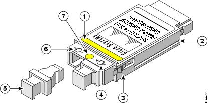
Figure B-9 CWDM GBIC Transceiver
|
|
Color arrow on label |
|
Optical bore dust plug |
|
|
Alignment groove |
|
Receive optical bore |
|
|
Spring clip |
|
Color dot |
|
|
Transmit optical bore |
Figure B-10 DWDM GBIC Transceiver Module
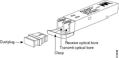
Figure B-11 CWDM SFP Transceiver
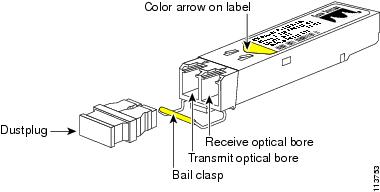
Figure B-12 DWDM XENPACK Transceiver
|
|
Captive installation screw |
|
Dustplug |
|
|
Transmit optical bore |
|
Receive optical bore |
 Feedback