Catalyst 3750-X and 3560-X Hardware Installation Guide
Bias-Free Language
The documentation set for this product strives to use bias-free language. For the purposes of this documentation set, bias-free is defined as language that does not imply discrimination based on age, disability, gender, racial identity, ethnic identity, sexual orientation, socioeconomic status, and intersectionality. Exceptions may be present in the documentation due to language that is hardcoded in the user interfaces of the product software, language used based on RFP documentation, or language that is used by a referenced third-party product. Learn more about how Cisco is using Inclusive Language.
- Updated:
- August 10, 2007
Chapter: Troubleshooting
Troubleshooting
•![]() Resetting the Switch to the Factory Default Settings
Resetting the Switch to the Factory Default Settings
•![]() Finding the Switch Serial Number
Finding the Switch Serial Number
•![]() Replacing a Failed Data Stack Member (Catalyst 3750-X Switches)
Replacing a Failed Data Stack Member (Catalyst 3750-X Switches)
Diagnosing Problems
The switch LEDs provide troubleshooting information about the switch. They show POST failures, port-connectivity problems, and overall switch performance. You can also get statistics from the device manager, the CLI, or an SNMP workstation. See the software configuration guide, the switch command reference guide on Cisco.com, or the documentation that came with your SNMP application for details.
Switch POST Results
As the switch powers on, it begins the power-on self-test (POST), a series of tests that runs automatically to ensure that the switch functions properly. It might take several minutes for the switch to complete POST.
When the switch begins POST, the Status LED turns green. The System LED blinks green, and the other LEDs stay green.
When POST completes successfully, the System LED remains green. The XPS LED is green for some time and then returns to its operating status. The other LEDs turn off and return to their operating status. If the switch fails POST, the System and Ethernet management port LEDs turn amber.

Note ![]() POST failures are usually fatal. Contact your Cisco technical support representative if your switch does not pass POST.
POST failures are usually fatal. Contact your Cisco technical support representative if your switch does not pass POST.
Switch LEDs
Look at the port LEDs for information when troubleshooting the switch. See the "LEDs" section for descriptions of the LED colors and their meanings.
Switch Connections
Bad or Damaged Cable
Always examine the cable for marginal damage or failure. A cable might be just good enough to connect at the physical layer, but it could corrupt packets as a result of subtle damage to the wiring or connectors. You can identify this situation because the port has many packet errors or the port constantly flaps (loses and regains link).
•![]() Exchange the copper or fiber-optic cable with a known good cable.
Exchange the copper or fiber-optic cable with a known good cable.
•![]() Look for broken or missing pins on cable connectors.
Look for broken or missing pins on cable connectors.
•![]() Rule out any bad patch panel connections or media convertors between the source and destination. If possible, bypass the patch panel or eliminate media convertors (fiber-optic-to-copper).
Rule out any bad patch panel connections or media convertors between the source and destination. If possible, bypass the patch panel or eliminate media convertors (fiber-optic-to-copper).
•![]() Try the cable in another port to see if the problem follows the cable.
Try the cable in another port to see if the problem follows the cable.
•![]() Catalyst 3750-X switch StackWise cable: remove and inspect the cable and StackWise port for bent pins or damaged connectors. If the StackWise cable is bad, replace it with a known good cable.
Catalyst 3750-X switch StackWise cable: remove and inspect the cable and StackWise port for bent pins or damaged connectors. If the StackWise cable is bad, replace it with a known good cable.
Ethernet and Fiber Cables
Make sure that you have the correct cable:
•![]() For Ethernet, use Category 3 copper cable for 10 Mbps UTP connections. Use either Category 5, Category 5e, or Category 6 UTP for 10/100 or 10/100/1000 Mbps connections.
For Ethernet, use Category 3 copper cable for 10 Mbps UTP connections. Use either Category 5, Category 5e, or Category 6 UTP for 10/100 or 10/100/1000 Mbps connections.
•![]() Verify that you have the correct fiber-optic cable for the distance and port type. Make sure that the connected device ports match and use the same type encoding, optical frequency, and fiber type. For more information about cabling, see the "SFP and SFP+ Module Cable Specifications" section.
Verify that you have the correct fiber-optic cable for the distance and port type. Make sure that the connected device ports match and use the same type encoding, optical frequency, and fiber type. For more information about cabling, see the "SFP and SFP+ Module Cable Specifications" section.
•![]() Determine if a copper crossover cable was used when a straight-through was required, or the reverse. Enable auto-MDIX on the switch, or replace the cable. See Table 2-3 for recommended Ethernet cables.
Determine if a copper crossover cable was used when a straight-through was required, or the reverse. Enable auto-MDIX on the switch, or replace the cable. See Table 2-3 for recommended Ethernet cables.
Link Status
Verify that both sides have link. A broken wire or a shut down port can cause one side to show link even though the other side does not have link.
A port LED that is on does not guarantee that the cable is functional. It might have encountered physical stress, causing it to function at a marginal level. If the port LED does not turn on:
•![]() Connect the cable from the switch to a known good device.
Connect the cable from the switch to a known good device.
•![]() Make sure that both ends of the cable are connected to the correct ports.
Make sure that both ends of the cable are connected to the correct ports.
•![]() Verify that both devices have power.
Verify that both devices have power.
•![]() Verify that you are using the correct cable type. See "Connector and Cable Specifications" for more information.
Verify that you are using the correct cable type. See "Connector and Cable Specifications" for more information.
•![]() Look for loose connections. Sometimes a cable appears to be seated but is not. Disconnect the cable and then reconnect it.
Look for loose connections. Sometimes a cable appears to be seated but is not. Disconnect the cable and then reconnect it.
10/100/1000 Port Connections
A port appears to malfunction:
•![]() Verify the status of all ports. See Table 1-8 for descriptions of the LEDs and their meanings.
Verify the status of all ports. See Table 1-8 for descriptions of the LEDs and their meanings.
•![]() Use the show interfaces privileged EXEC command to see if the port is error-disabled, disabled, or shut down. Re-enable the port if necessary.
Use the show interfaces privileged EXEC command to see if the port is error-disabled, disabled, or shut down. Re-enable the port if necessary.
•![]() Verify the cable type. See "Connector and Cable Specifications."
Verify the cable type. See "Connector and Cable Specifications."
PoE Port Connections
A powered device connected to a PoE port does not receive power:
•![]() Verify the status of all ports. See Table 1-9 and Table 1-13 for descriptions of the LEDs and their meanings.
Verify the status of all ports. See Table 1-9 and Table 1-13 for descriptions of the LEDs and their meanings.
•![]() Use the show interfaces privileged EXEC command to see if the port is error-disabled, disabled, or shut down. Re-enable the port if necessary.
Use the show interfaces privileged EXEC command to see if the port is error-disabled, disabled, or shut down. Re-enable the port if necessary.
•![]() Verify that the power supply installed in the switch meets the power requirements of your connected devices. See the "Power Supply Modules" section for more information.
Verify that the power supply installed in the switch meets the power requirements of your connected devices. See the "Power Supply Modules" section for more information.
•![]() Verify the cable type. Many legacy powered devices, including older Cisco IP phones and access points that do not fully support IEEE 802.3af might not support PoE when connected to the switch by a crossover cable. Replace the crossover cable with a straight-through cable.
Verify the cable type. Many legacy powered devices, including older Cisco IP phones and access points that do not fully support IEEE 802.3af might not support PoE when connected to the switch by a crossover cable. Replace the crossover cable with a straight-through cable.

Note ![]() The output of the PoE circuit has been evaluated as a limited power source (LPS) per IEC 60950.
The output of the PoE circuit has been evaluated as a limited power source (LPS) per IEC 60950.
SFP Modules
Use only Cisco network modules and SFP modules.
•![]() Inspect the network module and SFP module. Exchange the suspect module with a known good module.
Inspect the network module and SFP module. Exchange the suspect module with a known good module.
•![]() Verify that the module is supported on this platform. (The switch release notes on Cisco.com list the SFP and SFP+ modules that the switch supports.)
Verify that the module is supported on this platform. (The switch release notes on Cisco.com list the SFP and SFP+ modules that the switch supports.)
•![]() Use the show interfaces privileged EXEC command to see if the port or module is error-disabled, disabled, or shut down. Re-enable the port if needed.
Use the show interfaces privileged EXEC command to see if the port or module is error-disabled, disabled, or shut down. Re-enable the port if needed.
•![]() Make sure that all fiber connections are clean and securely connected.
Make sure that all fiber connections are clean and securely connected.
•![]() For CX1 module connections, make sure that cable routing does not violate the minimum allowed cable bend radius. See the module documentation for specific cabling requirements.
For CX1 module connections, make sure that cable routing does not violate the minimum allowed cable bend radius. See the module documentation for specific cabling requirements.
Note ![]() When ordering or using CX1 cables, ensure that the version identifier is 2 or higher.
When ordering or using CX1 cables, ensure that the version identifier is 2 or higher.
•![]() For long wave SFP+ modules, a mode conditioning patch might improve performance over maximum link distances with MMF connections.
For long wave SFP+ modules, a mode conditioning patch might improve performance over maximum link distances with MMF connections.
Interface Settings
Verify that the port or interface is not disabled or powered off. If a port or interface is manually shut down on either side of the link, it does not come up until you re-enable the interface. Use the show interfaces privileged EXEC command to see if the interface is error-disabled, disabled, or shut down on either side of the connection. If needed, re-enable the interface.
Ping End Device
Ping from the directly connected switch first, and then work your way back port by port, interface by interface, trunk by trunk, until you find the source of the connectivity issue. Make sure that each switch can identify the end device MAC address in its Content-Addressable Memory (CAM) table.
Spanning Tree Loops
STP loops can cause serious performance issues that look like port or interface problems.
A unidirectional link can cause loops. It occurs when the traffic sent by the switch is received by the neighbor, but the traffic from the neighbor is not received by the switch. A broken cable, other cabling problems, or a port issue could cause this one-way communication.
You can enable UniDirectional Link Detection (UDLD) on the switch to help identify unidirectional link problems. For information about enabling UDLD on the switch, see the "Understanding UDLD" section in the software configuration guide on Cisco.com.
Switch Performance
Speed, Duplex, and Autonegotiation
Port statistics that show a large amount of alignment errors, frame check sequence (FCS), or late-collisions errors, might mean a speed or duplex mismatch.
A common issue occurs when duplex and speed settings are mismatched between two switches, between a switch and a router, or between the switch and a workstation or server. Mismatches can happen when manually setting the speed and duplex or from autonegotiation issues between the two devices.
To maximize switch performance and to ensure a link, follow one of these guidelines when changing the duplex or the speed settings:
•![]() Let both ports autonegotiate both speed and duplex.
Let both ports autonegotiate both speed and duplex.
•![]() Manually set the speed and duplex parameters for the interfaces on both ends of the connection.
Manually set the speed and duplex parameters for the interfaces on both ends of the connection.
•![]() If a remote device does not autonegotiate, use the same duplex settings on the two ports. The speed parameter adjusts itself even if the connected port does not autonegotiate.
If a remote device does not autonegotiate, use the same duplex settings on the two ports. The speed parameter adjusts itself even if the connected port does not autonegotiate.
Autonegotiation and Network Interface Cards
Problems sometimes occur between the switch and third-party network interface cards (NICs). By default, the switch ports and interfaces autonegotiate.Laptops or other devices are commonly set to autonegotiate, yet sometimes issues occur.
To troubleshoot autonegotiation problems, try manually setting both sides of the connection. If this does not solve the problem, there could be a problem with the firmware or software on the NIC. You can resolve this by upgrading the NIC driver to the latest version.
Cabling Distance
If the port statistics show excessive FCS, late-collision, or alignment errors, verify that the cable distance from the switch to the connected device meets the recommended guidelines. See the "Cable and Adapter Specifications" section.
Resetting the Switch to the Factory Default Settings
If you have configured a new switch with a wrong IP address, or if all of the switch LEDs start blinking when you try to enter Express Setup mode, you can clear the IP address that is configured on the switch.
Note ![]() Resetting the switch deletes the configuration and reboots the switch.
Resetting the switch deletes the configuration and reboots the switch.
To reset the switch:
1. ![]() Press and hold the Mode button (Figure 1-2).
Press and hold the Mode button (Figure 1-2).
The switch LEDs begin blinking after about 2 seconds. If the LEDs above the mode button turn solid green, you can release the Mode button and run Express Setup to configure the switch. If the LEDs do not turn solid green, continue with the next step.
2. ![]() Continue holding down the Mode button. The LEDs stop blinking after an additional 8 seconds, and then the switch reboots.
Continue holding down the Mode button. The LEDs stop blinking after an additional 8 seconds, and then the switch reboots.
The switch now behaves like an unconfigured switch. You can configure the switch by using Express Setup as described in the switch getting started guide on Cisco.com.
You can also configure the switch by using the CLI setup procedure. See "Configuring the Switch with the CLI-Based Setup Program."
Finding the Switch Serial Number
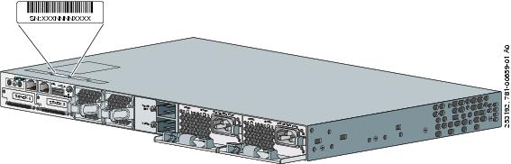
If you contact Cisco Technical Assistance, you need to know the switch serial number. Figure 4-1 shows the serial number location. You can also use the show version privileged EXEC command to see the switch serial number.
Figure 4-1 Switch Serial Number Location
Replacing a Failed Data Stack Member (Catalyst 3750-X Switches)
To replace a failed data stack member:
1. ![]() The replacement switch must be a Catalyst 3750-X switch.
The replacement switch must be a Catalyst 3750-X switch.
2. ![]() Power down the failed switch. Remove AC or DC input power, and if the switch is part of a StackPower stack, remove the StackPower cables.
Power down the failed switch. Remove AC or DC input power, and if the switch is part of a StackPower stack, remove the StackPower cables.
3. ![]() Make sure the replacement switch is powered off, and then connect it to the stack.
Make sure the replacement switch is powered off, and then connect it to the stack.
If you had manually set the member numbers for the switch stack, manually assign the member number of the failed switch to the replacement switch. To manually assign the stack member number, see the switch software configuration guide on Cisco.com.
4. ![]() Make the same Gigabit Ethernet connections on the replacement switch that were on the failed switch.
Make the same Gigabit Ethernet connections on the replacement switch that were on the failed switch.
5. ![]() Reinstall any modules and cable connections.
Reinstall any modules and cable connections.
6. ![]() Power on the replacement switch.
Power on the replacement switch.
The replacement switch will have the same configuration for all the interfaces as the failed switch and will function the same as the failed switch.
 Feedback