Downloads |
 Feedback Feedback
|
Table Of Contents
Information About Managing VDCs
Saving All VDC Configurations to the Startup Configuration
Licensing Requirements for Managing VDCs
Prerequisites for Managing VDCs
Guidelines and Limitations for Managing VDCs
Changing the Nondefault VDC Prompt Format
Allocating Interfaces to an Ethernet VDC
Applying a VDC Resource Template
Configuring the VDC Boot Order
Verifying the VDC Configuration
Configuration Examples for VDC Management
Related Documents for Managing VDCs
Feature History for Managing VDCs
Managing VDCs
This chapter describes how to manage virtual device contexts (VDCs) on Cisco NX-OS devices.
This chapter includes the following sections:
•
Information About Managing VDCs
•
•
•
•
•
•
Information About Managing VDCs
After you create a VDC, you can change the interface allocation, VDC resource limits, and the single-supervisor and dual-supervisor high availability (HA) policies. You can also save the running configuration of all VDCs on the physical device to the startup configuration.
This section includes the following topics:
•
Interface Allocation
Note
When you create a VDC, you can allocate I/O interfaces to the VDC. Later, the deployment of your physical device might change, and you can reallocate the interfaces as necessary.
Note
The following Cisco Nexus 7000 Series Ethernet modules have the following number of port groups and interfaces:
•
•
•
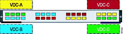
Figure 4-1 Example Interface Allocation for Port Groups on the Cisco Nexus 7000 Series 10-Gbps Ethernet Module N7K-M132XP-12
Table 4-1 shows the port numbering for the port groups.
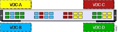
On the Cisco Nexus 7000 Series 32-port, 10-Gbps Ethernet module N7K-F132XP-15, you must allocate the interfaces on your physical device in the specified combination. This module has 16 port groups that consist of 2 ports each (2 interfaces x 16 port groups = 32 interfaces). Interfaces belonging to the same port group must belong to the same VDC (see Figure 4-2).
Note
Figure 4-2 Example Interface Allocation for Port Groups on the Cisco Nexus 7000 Series 10-Gbps Ethernet Module N7K-F132XP-15
Table 4-2 shows the port numbering for the port groups.
For more information about port groups on the Cisco Nexus 7000 Series 10-Gbps Ethernet modules, see the Cisco Nexus 7000 Series Hardware Installation and Reference Guide.
Note
When interfaces in different VDCs share the same port ASIC, reloading the VDC (with the reload vdc command) or provisioning interfaces to the VDC (with the allocate interface command) might cause short traffic disruptions (of 1 to 2 seconds) for these interfaces. If such behavior is undesirable, make sure to allocate all interfaces on the same port ASIC to the same VDC.
To see how the interfaces are mapping to the port ASIC, use this command:
slot slot_number show hardware internal dev-port-map
+--------------------------------------------------------------++-----------+++FRONT PANEL PORT TO ASIC INSTANCE MAP+++--------++--------------------------------------------------------------+FP port|PHYS |SECUR |MAC_0 |RWR_0 |L2LKP |L3LKP |QUEUE |SWICHF1 0 0 0 0 0 0 0 02 0 0 0 0 0 0 0 03 0 0 0 0 0 0 0 04 0 0 0 0 0 0 0 05 0 1 0 0 0 0 0 06 0 1 0 0 0 0 0 07 0 1 0 0 0 0 0 08 0 1 0 0 0 0 0 09 1 2 0 0 0 0 0 010 1 2 0 0 0 0 0 011 1 2 0 0 0 0 0 012 1 2 0 0 0 0 0 013 1 3 1 0 0 0 0 014 1 3 1 0 0 0 0 015 1 3 1 0 0 0 0 016 1 3 1 0 0 0 0 017 2 4 1 0 0 0 0 0The interface number is listed in the FP port column, and the port ASIC number is listed in the MAC_0 column, which means that in the above example, interfaces 1 through 12 share the same port ASIC (0).
VDC Resource Limits
You can change the resource limits for your VDC individually or by applying a VDC resource template as your needs change. You can change the following limits for the following resources:
•
•
•
•
•
•
•
•
HA Policies
The HA policy determines the action that the physical device takes when the VDC encounters an unrecoverable field. You can change the HA policy for the VDC that was specified when you created the VDC.
Note
Saving All VDC Configurations to the Startup Configuration
From the VDC, a user with the vdc-admin or network-admin role can save the VDC configuration to the startup configuration. However, you might want to save the configuration of all VDCs to the startup configuration from the default VDC.
Suspending and Resuming VDCs
Users with the network-admin role can suspend and resume a nondefault VDC. You must save the VDC running configuration to the startup configuration before suspending the VDC. Otherwise, you will lose the changes to the running configuration when you resume the VDC. You cannot remove interfaces allocated to a suspended VDC. All other resources in use by the VDC are released while the VDC is suspended.
Note
Note
Caution
VDC Reload
You can load an active nondefault VDC that is in any state. The impact of reloading a nondefault VDC is similar to reloading a physical device. The VDC reloads using the startup configuration.
Note
Caution
MAC Addresses
The default VDC has a management MAC address. Beginning with Cisco Release 5.2(1) for the Cisco Nexus 7000 Series devices, subsequent nondefault VDCs that you create are assigned MAC addresses automatically as part of the bootup process.
You will see a syslog message if there are not sufficient MAC addresses to supply all the VDCs on the device.
VDC Boot Order
You can specify the boot order for the VDCs on the Cisco NX-OS device. By default, all VDCs start in parallel with no guarantee as to which VDC completes starting first. Using the boot order value, the Cisco NX-OS software starts the VDCs in a predictable sequence. The boot order feature has the following characteristics:
•
•
•
•
•
Licensing Requirements for Managing VDCs
The following table shows the licensing requirements for this feature:
Prerequisites for Managing VDCs
VDC management has the following prerequisites:
•
•
Guidelines and Limitations for Managing VDCs
VDC management has the following configuration guidelines and limitations:
•
•
•
•
•
Managing VDCs
This section includes the following topics:
•
•
•
•
Changing the Nondefault VDC Prompt Format
You can change the format of the CLI prompt for nondefault VDCs. By default, the prompt format is a combination of the default VDC name and the nondefault VDC name. You can change the prompt to only contain the nondefault VDC name.
BEFORE YOU BEGIN
Log in to the default VDC with a username that has the network-admin user role.
SUMMARY STEPS
1.
2.
3.
Allocating Interfaces to an Ethernet VDC
Note
You can allocate one or more interfaces to a VDC. When you allocate an interface, you move it from one VDC to another VDC. The interfaces are in the down state after you move them.
Note
Note
BEFORE YOU BEGIN
Log in to the default VDC with a username that has the network-admin user role.
SUMMARY STEPS
1.
2.
3.
4.
allocate interface ethernet slot/port - last-port
allocate interface ethernet slot/port, ethernet slot/port, ...
5.
6.
7.
DETAILED STEPS
Applying a VDC Resource Template
You can change the VDC resource limits by applying a new VDC resource template. Changes to the limits take effect immediately except for the IPv4 and IPv6 route memory limits, which take effect after the next VDC reset, physical device reload, or physical device stateful switchover.
BEFORE YOU BEGIN
Log in to the default VDC with a username that has the network-admin user role.
SUMMARY STEPS
1.
2.
3.
4.
5.
6.
7.
DETAILED STEPS
Changing VDC Resource Limits
You can change the limits on the VDC resources. Changes to the limits take effect immediately except for the IPv4 and IPv6 routing table memory limits, which take effect after the next VDC reset, physical device reload, or physical device stateful switchover.
Note
Note
BEFORE YOU BEGIN
Log in to the default VDC with a username that has the network-admin user role.
SUMMARY STEPS
1.
2.
3.
4.
limit-resource m6route-mem [minimum min-value] maximum max-value
limit-resource monitor-session minimum min-value maximum {max-value | equal-to-min}
limit-resource monitor-session-erspan-dst minimum min-value maximum {max-value | equal-to-min}
limit-resource port-channel minimum min-value maximum {max-value | equal-to-min}
limit-resource u4route-mem [minimum min-value] maximum max-value
limit-resource u6route-mem [minimum min-value] maximum max-value
limit-resource vlan minimum min-value maximum {max-value | equal-to-min}
limit-resource vrf minimum min-value maximum {max-value | equal-to-min}
limit-resource linecard-type {M1 | F1}
5.
6.
7.
DETAILED STEPS
Changing the HA Policies
You can change the HA policies for a VDC. The VDC HA policies are as follows:
•
–
–
–
•
–
–
Caution
Note
–
Caution
Note
BEFORE YOU BEGIN
Log in to the default VDC with a username that has the network-admin user role.
SUMMARY STEPS
1.
2.
3.
4.
5.
6.
DETAILED STEPS
Saving VDC Configurations
You can save the configuration of all the VDCs on the physical device to the startup configuration.
BEFORE YOU BEGIN
Log in to the default VDC with a username that has the network-admin user role.
SUMMARY STEPS
1.
2.
3.
4.
DETAILED STEPS
Suspending a Nondefault VDC
You can suspend an active nondefault VDC. You must save the VDC running configuration to the startup configuration before suspending the VDC. Otherwise, you will lose the changes to the running configuration.
Note
Caution
BEFORE YOU BEGIN
Log in to the default VDC with a username that has the network-admin user role.
SUMMARY STEPS
1.
2.
3.
DETAILED STEPS
Resuming a Nondefault VDC
You can resume a nondefault VDC from the suspended state. The VDC resumes with the configuration saved in the startup configuration.
BEFORE YOU BEGIN
Log in to the default VDC with a username that has the network-admin user role.
SUMMARY STEPS
1.
2.
DETAILED STEPS
Reloading a Nondefault VDC
You can load a nondefault VDC that is in a failed state. The VDC reloads using the startup configuration.
Note
Caution
BEFORE YOU BEGIN
Log in to the nondefault VDC with a username that has the vdc-admin user role or use the switchto vdc command from the default VDC to access the nondefault VDC.
SUMMARY STEPS
1.
2.
DETAILED STEPS
Configuring the VDC Boot Order
You can configure the boot order for the VDCs on your Cisco NX-OS device.
Note
BEFORE YOU BEGIN
Log in to the default VDC with a username that has the network-admin user role.
SUMMARY STEPS
1.
2.
3.
4.
5.
6.
DETAILED STEPS
Deleting a VDC
When you delete a VDC, the ports on the VDC are moved to unallocated interfaces. To allocate the interfaces back to the VDC, see the "Allocating Interfaces to an Ethernet VDC" section.
Note
Caution
BEFORE YOU BEGIN
Log in to the default VDC with a username that has the network-admin user role.
SUMMARY STEPS
1.
2.
3.
4.
5.
DETAILED STEPS
Verifying the VDC Configuration
To display the VDC configuration, perform one of the following tasks:
For detailed information about the fields in the output from these commands, see the Cisco Nexus 7000 Series NX-OS Virtual Device Context Command Reference.
Configuration Examples for VDC Management
The following example shows how to allocate interfaces between VDCs for port groups on a Cisco Nexus 7000 Series 32-port, 10-Gbps Ethernet module as described in Figure 4-1:
Note
config thostname VDC-Avdc VDC-B! Port group 2allocate interfaces ethernet 2/2, ethernet 2/4, ethernet 2/6, ethernet 2/8! Port group 3allocate interfaces ethernet 2/9, ethernet 2/11, ethernet 2/13, ethernet 2/15vdc VDC-C! Port group 4allocate interfaces ethernet 2/10, ethernet 2/12, ethernet 2/14, ethernet 2/16! Port group 5allocate interfaces ethernet 2/17, ethernet 2/19, ethernet 2/21, ethernet 2/23vdc VDC-D! Port group 6allocate interfaces ethernet 2/18, ethernet 2/20, ethernet 2/22, ethernet 2/24! Port group 7allocate interfaces ethernet 2/25, ethernet 2/27, ethernet 2/29, ethernet 2/30Additional References
For additional information related to managing VDCs, see the following sections:
•
Related Documents for Managing VDCs
Feature History for Managing VDCs
Table 4-3 lists the release history for this feature.