Downloads |
 Feedback Feedback
|
Table Of Contents
Information About FabricPath Interfaces
STP and the FabricPath Network
Licensing Requirements for FabricPath Interfaces
Prerequisites for FabricPath Interfaces
Guidelines and Limitations for FabricPath Interfaces
Configuring FabricPath Interfaces
Configuring FabricPath Interfaces
Configuring the STP Priority with Rapid PVST+
Configuring the STP Priority with MST
(Optional) Configuring the STP Domain ID for STP Domains Connected to the Layer 2 Gateway Switch
Verifying FabricPath Interface Configuration
Displaying FabricPath Interface Statistics
FabricPath Interface Example Configuration
Feature History for Configuring FabricPath Using the CLI
FabricPath Interfaces
This chapter describes how to configure the FabricPath interfaces on the Cisco NX-OS devices.
This chapter includes the following sections:
•
Information About FabricPath Interfaces
•
•
•
•
•
•
•
•
Information About FabricPath Interfaces
This section includes the following sections:
•
•
Note
FabricPath Interfaces
After you enable FabricPath on the devices that you are using, you can configure an Ethernet interface or a port-channel interface as a FabricPath interface. If one member of the port channel is in FabricPath mode, all the other members will be in FabricPath mode. After you configure the interface as a FabricPath interface, it automatically becomes a trunk port, capable of carrying traffic for multiple VLANs. You can also configure all the ports on the F Series module as FabricPath interfaces simultaneously.
The following interface modes carry traffic for the following types of VLANs:
•
•
–
–
•
Note
The FabricPath interfaces connect only to other FabricPath interfaces within the FabricPath network. These FabricPath ports operate on the information in the FabricPath headers and Layer 2 Intermediate System-to-Intermediate System (IS-IS) only, and they do not run STP. These ports are aware only of FP VLANs; they are unaware of any CE VLANs. By default, all VLANs are allowed on a trunk port, so the FabricPath interface carries traffic for all FP VLANs.
Note
STP and the FabricPath Network
Note
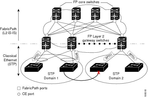
The Spanning Tree Protocol (STP) domains do not cross into the FabricPath network (see Figure 3-1).
Figure 3-1 STP Boundary Termination at FabricPath Network Border
You must configure the FabricPath Layer 2 gateway device to have the lowest STP priority of all the devices in the STP domain to which it is attached. You must also configure all the FabricPath Layer 2 gateway devices connected to one FabricPath network to have the same priority. The system assigns the bridge ID for the Layer 2 gateway devices from a pool of reserved MAC addresses.
To have a loop-free topology for the CE/FabricPath hybrid network, the FabricPath network automatically displays as a single bridge to all connected CE devices.
Note
Other than configuring the STP priority on the FabricPath Layer 2 gateway switches, you do not need to configure anything for the STP to work seamlessly with the FabricPath network. Only connected CE devices form a single STP domain. Those CE devices that are not interconnected form separate STP domains (see Figure 3-1).
All CE interfaces should be designated ports, which occurs automatically, or they are pruned from the active STP topology. If the system does prune any port, the system returns a syslog message. The system clears the port again only when that port is no longer receiving superior BPDUs.
The FabricPath Layer 2 gateway switch also propagates the Topology Change Notifications (TCNs) on all its CE interfaces.
The FabricPath Layer 2 gateway switches terminate STP. The set of FabricPath Layer 2 gateway switches that are connected by STP forms the STP domain. Because there can be many FabricPath Layer 2 gateway switches attached to a single FabricPath network, there may also be many separate STP domains (see Figure 3-1). The devices in the separate STP domains need to know the TCN information only for the domain to which they belong. You can configure a unique STP domain ID for each separate STP domain that connects to the same FabricPath network. The Layer 2 IS-IS messages carry the TCNs across the FabricPath network. Only those FabricPath Layer 2 gateway switches in the same STP domain as the TCN message need to act and propagate the message to connected CE devices.
When a FabricPath Layer 2 gateway switch receives a TCN for the STP domain it is part of, it takes the following actions:
•
•
The devices in the separate STP domains need to receive the TCN information and then flush all remote MAC addresses reachable by the STP domain that generated the TCN information.
vPC+
A virtual port channel+ (vPC+) domain allows a classical Ethernet (CE) vPC domain and a Cisco FabricPath cloud to interoperate. a vPC+ also provides a First Hop Routing Protocol (FHRP) active-active capability at the FabricPath to Layer 3 boundary.
Note
A vPC+ domain enables Cisco Nexus 7000 Series enabled with FabricPath devices to form a single vPC+, which is a unique virtual switch to the rest of the FabricPath network. You configure the same domain on each device to enable the peers to identify each other and to form the vPC+. Each vPC+ has its own virtual switch ID.
Note
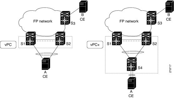
A vPC+ must still provide active-active Layer 2 paths for dual-homed CE devices or clouds, even though the FabricPath network allows only 1-to-1 mapping between the MAC address and the switch ID. vPC+ provides the solution by creating a unique virtual switch to the FabricPath network (see Figure 3-2).
Figure 3-2 vPC/vPC+
The FabricPath switch ID for the virtual switch becomes the outer source MAC address (OSA) in the FabricPath encapsulation header. Each vPC+ domain must have its own virtual switch ID.
Layer 2 multipathing is achieved by emulating a single virtual switch. Packets forwarded from host A to host B are tagged with the MAC address of the virtual switch as the transit source, and traffic from host B to host A is now load balanced.
You must have all interfaces in the vPC+ peer link as well as all the downstream vPC+ links on an F Series module with FabricPath enabled. The vPC+ downstream links will be FabricPath edge interfaces, which connect to the CE hosts.
The vPC+ virtual switch ID is used to assign the FabricPath Outer Source Address (OSA) to the FabricPath vPC+ peer devices (see Chapter 2 "Configuring FabricPath Switching", for information on FabricPath encapsulation). You must assign the same switch ID to each of the two vPC+ peer devices so the peer link can form.
The F1 Series modules have only Layer 2 interfaces. To use routing with a vPC+, you must have an M Series module inserted into the same Cisco Nexus 7000 Series chassis. The system then performs proxy routing using both the N7K-F132-15 module and the M Series modules in the chassis (see the Cisco Nexus 7000 Series NX-OS Unicast Routing Configuration Guide, Release 5.x for information on proxy routing with the F1 Series modules).
The First Hop Routing Protocols (FHRP) and the Hot Standby Routing Protocol (HSRP) interoperate with a vPC+. You should dual-attach all Layer 3 devices to both vPC+ peer devices.
Note
The primary FHRP device responds to ARP requests, even though the secondary vPC+ device also forwards the data traffic. Both the primary and secondary vPC+ devices forward traffic, but only the primary FHRP device responds to ARP requests.
To simplify initial configuration verification and vPC+/HSRP troubleshooting, you can configure the primary vPC+ peer device with the FHRP active router highest priority.
In addition, you can use the priority command in the if-hsrp configuration mode to configure failover thresholds for when a group state enabled on a vPC+ peer is in standby or in listen state. You can configure lower and upper thresholds to prevent the group state flap, if there is an interface flap (this feature is useful when there is more than one tracking object per group).
When the primary vPC+ peer device fails over to the secondary vPC+ peer device, the FHRP traffic continues to flow seamlessly.
You should configure a separate Layer 3 link for routing from the vPC+ peer devices, rather than using a VLAN network interface for this purpose.
We do not recommend that you configure the burnt-in MAC address option (use-bia) for hot standby router protocol HSRP or manually configure virtual MAC addresses for any FHRP protocol in a vPC+ environment because these configurations can adversely affect the vPC+ load balancing. The HSRP use-bia is not supported with a vPC+. When you are configuring custom MAC addresses, you must configure the same MAC address on both vPC+ peer devices.
You can configure a restore timer that delays the vPC+ coming back up until after the peer adjacency forms and the VLAN interfaces are back up. This feature allows you to avoid packet drops if the routing tables do not converge before the vPC+ is once again passing traffic.
Use the delay restore command to configure this feature.
Note
The delay option is only available with HSRP. If you use any other FHRP, traffic loss is still possible.
See the Cisco Nexus 7000 Series NX-OS Unicast Routing Configuration Guide, Release 5.x, for more information on FHRPs and routing.
High Availability
The FabricPath topologies retain their configuration through an in-service software upgrade (ISSU).
See the Cisco Nexus 7000 Series NX-OS High Availability and Redundancy Guide, Release 5.x, for more information on high availability.
Virtual Device Contexts
You must install the FabricPath feature set before you enable FabricPath on the switch. See Configuring Feature Set for FabricPath for information on installing the FabricPath feature set.
Because of the multiple forwarding engines (FEs) on the F Series modules, the following port pairs must be in the same VDC:
•
•
•
•
•
•
•
•
•
•
•
•
•
•
•
•
See the Virtual Device Context Configuration Guide, Cisco DCNM for LAN, Release 5.x, for more information on VDCs.
Licensing Requirements for FabricPath Interfaces
The following table shows the licensing requirements for this feature:
Prerequisites for FabricPath Interfaces
FabricPath interfaces have the following prerequisites:
•
•
•
•
•
•
•
Guidelines and Limitations for FabricPath Interfaces
FabricPath has the following configuration guidelines and limitations:
•
•
•
•
•
•
–
–
•
•
Configuring FabricPath Interfaces
Note
This section includes the following topics:
•
•
•
•
Note
Configuring FabricPath Interfaces
Note
You configure the interfaces for the FabricPath network to be FabricPath interfaces.
BEFORE YOU BEGIN
Ensure that you are working on an F Series module.
Ensure that you have enabled the FabricPath feature on all devices.
Ensure that you have installed the Enhanced Layer 2 license.
SUMMARY STEPS
1.
2.
3.
4.
5.
6.
7.
DETAILED STEPS
This example shows how to configure specified interfaces as FabricPath interfaces:
switch# config terminalswitch(config)# interface ethernet 2/11-15switch(config-if)# switchport mode fabricpathswitch(config-if)#Configuring the STP Priority with Rapid PVST+
All Layer 2 gateway devices must have the same bridge priority when they are in the same STP domain. Make sure that the STP priority configured for the Layer 2 gateway devices on a FabricPath network is the lowest value in the Layer 2 network. Additionally, the priorities must match.
We recommend that you configure the STP priority on all FabricPath Layer 2 gateway devices to 8192.
BEFORE YOU BEGIN
Ensure that you are working on an F Series module.
Ensure that you have enabled the FabricPath feature on all devices.
Ensure that you have installed the Enhanced Layer 2 license.
SUMMARY STEPS
1.
2.
3.
4.
5.
DETAILED STEPS
This example shows how to configure the Rapid PVST+ VLANs on the FabricPath Layer 2 gateway devices to have an STP priority of 8192:
switch# config terminalswitch(config)# spanning-tree vlan 11-20 priority 8192switch(config)#See the Cisco Nexus 7000 Series NX-OS Layer 2 Switching Command Reference for more information on this command.
Configuring the STP Priority with MST
All Layer 2 gateway devices must have the same bridge priority when they are in the same STP domain. Make sure that the STP priority configured for the Layer 2 gateway devices on a FabricPath network is the lowest value in the Layer 2 network. Additionally, the priorities must match.
You configure the STP priority for all Multiple Spanning-Tree (MST) instances on all FabricPath Layer 2 gateway devices to 8192.
BEFORE YOU BEGIN
Ensure that you are working on an F Series module.
Ensure that you have enabled the FabricPath feature on all devices.
Ensure that you have installed the Enhanced Layer 2 license.
SUMMARY STEPS
1.
2.
3.
4.
5.
DETAILED STEPS
This example shows how to configure the MST instances on the FabricPath Layer 2 gateway devices to have an STP priority of 8192:
switch# config terminalswitch(config)# spanning-tree mst 1-5 priority 8192switch(config)#See the Cisco Nexus 7000 Series NX-OS Layer 2 Switching Command Reference for more information on this command.
(Optional) Configuring the STP Domain ID for STP Domains Connected to the Layer 2 Gateway Switch
Because there can be many FabricPath Layer 2 gateway switches attached to a single FabricPath network, there are also many separate STP domains that are each connected to a Layer 2 gateway switch. You can configure a unique STP domain ID in the FabricPath network to propagate TCNs across all the STP domains that are connected to the FabricPath network. To ensure that all the MAC addresses are flushed when the system receives a TCN.
BEFORE YOU BEGIN
Ensure that you are working on an F Series module.
Ensure that you have enabled the FabricPath feature on all devices.
Ensure that you have installed the Enhanced Layer 2 license.
SUMMARY STEPS
1.
2.
3.
4.
5.
DETAILED STEPS
This example shows how to configure the STP domain ID attached to the FabricPath Layer 2 gateway device:
switch# config terminalswitch(config)# spanning-tree domain 5switch(config)# exitswitchConfiguring a vPC+ Switch ID
Note
You configure the vPC+ switch ID by using the fabricpath switch-id command.
Note
See the Cisco Nexus 7000 Series NX-OS Interfaces Configuration Guide, Release 5.x, for complete information on configuring vPCs.
BEFORE YOU BEGIN
Ensure that you are working on an F Series module.
Ensure that you have enabled the vPC feature.
Ensure that you have enabled the FabricPath feature.
Ensure that you are in the correct VDC (or use the switchto vdc command).
SUMMARY STEPS
1.
2.
3.
DETAILED STEPS
This example shows how to configure a vPC+ switch ID on each vPC+ peer device:
switch# configure terminalswitch(config)# vpc domain 1switch(config-vpc-domain)# fabricpath switch-id 1Verifying FabricPath Interface Configuration
To display FabricPath interfaces information, perform one of the following tasks:
For information on the above commands, see the Cisco Nexus 7000 Series NX-OS Interfaces Command Reference and the Cisco Nexus 7000 Series NX-OS Layer 2 Switching Command Reference.
Displaying FabricPath Interface Statistics
Use the following command to display FabricPath statistics:
•
•
•
•
FabricPath Interface Example Configuration
To configure FabricPath interfaces, perform the following tasks on each device:
•
•
•
•
•
To configure FabricPath interfaces, follow these steps:
Step 1
switch# config terminalswitch(config)# feature fabricpathswitch(config-lldp)# exitswitch(config)#Step 2
switch(config)# interface ethernet 1/2switch(config-if)# switchport mode fabricpathswitch(config-if)# exitswitch(config)#Step 3
switch# config terminalswitch(config)# spanning-tree vlan 11-20 priority 8192switch(config)#Step 4
switch# config terminalswitch(config)# spanning-tree mst 1-5 priority 8192switch(config)#Step 5
switch# config terminalswitch(config)# spanning-tree domain 5switch(config)Step 6
switch# config terminalswitch(config)# vpc domain 5switch(config-vpc-domain)# fabricpath switch-id 100switch(config-vpc-domain)# exitswitch(config)
Note
If you are configuring the vPC+ with no existing vPC+, follow these steps:
1.
2.
3.
If you are changing an existing vPC configuration to a vPC+ on an F Series module, follow these steps:
1.
2.
3.
4.
Step 7
switch(config)# save running-config startup-configswitch(config)#When you are configuring vPC+, and you see the following situations, you must enter the shutdown command and then the no shutdown command on all the peer-link interfaces:
•
•
Feature History for Configuring FabricPath Using the CLI
Table 3-1 lists the release history for this feature.
Table 3-1 Feature History for FabricPath
FabricPath Interfaces
5.1(1)
These features were introduced.