-
Cisco MDS 9000 Family Troubleshooting Guide, Release 3.x
-
Index
-
New and Changed Information
-
Preface
-
Troubleshooting Overview
-
Troubleshooting Installs, Upgrades, and Reboots
-
Managing Storage Services Modules
-
Troubleshooting Hardware
-
Troubleshooting Mixed Generation Hardware
-
Troubleshooting Licensing
-
Troubleshooting Cisco Fabric Services
-
Troubleshooting Ports
-
Troubleshooting N-Port Virtualization
-
Troubleshooting PortChannels and Trunking
-
Troubleshooting VSANs, Domains, and FSPF
-
Troubleshooting SAN Device Virtualization
-
Troubleshooting IVR
-
Troubleshooting Zones and Zone Sets
-
Troubleshooting Distributed Device Alias Services
-
Troubleshooting FICON
-
Troubleshooting RADIUS and TACACS+
-
Troubleshooting Users and Roles
-
Troubleshooting FC-SP, Port Security, and Fabric Binding
-
Troubleshooting IP Storage Services
-
Troubleshooting IP Access Lists
-
Troubleshooting IPsec
-
Troubleshooting SANTap
-
Troubleshooting Digital Certificates
-
Troubleshooting Call Home
-
Troubleshooting Fabric Manager
-
Before Contacting Technical Support
-
Troublelshooting Tools and Methodology
-
Configuration Limits for Cisco MDS SAN-OS Release 3.x
-
 Feedback
Table Of Contents
Troubleshooting Installs, Upgrades, and Reboots
Troubleshooting a Nondisruptive Upgrade on a Fabric Switch
Troubleshooting Fabric Manager Installations
Verifying Cisco SAN-OS Software Installations
Troubleshooting Cisco SAN-OS Software Upgrades and Downgrades
Software Installation Reports an Incompatibility
Diagnosing Compatibility Issues
Software Installation Ends with Error
Installing SAN-OS Software Using Fabric Manager
Installing Cisco SAN-OS Software from the CLI
Troubleshooting Cisco SAN-OS Software System Reboots
Power On or Switch Reboot Hangs
Recovery Using BIOS Setup for Supervisor-1
Recovery from the loader> Prompt on Supervisor-2 Modules
Recovery from the loader> Prompt on Supervisor-1 Modules
Recovery from the switch(boot)# Prompt
Recovery for Switches with Dual Supervisor Modules
Recovering One Supervisor Module With Corrupted Bootflash
Recovering Both Supervisor Modules With Corrupted Bootflash
Recovering the Administrator Password
Miscellaneous Software Image Issues
All Ports Down Because of System Health Failure
Switch Reboots after FCIP Reload
Cannot Create, Modify, or Delete Admin Role
FC IDs Change after Link Reset
Troubleshooting Installs, Upgrades, and Reboots
This chapter describes how to identify and resolve problems that might occur when installing, upgrading, or restarting Cisco MDS 9000 Family products.
It includes the following sections:
•
Troubleshooting a Nondisruptive Upgrade on a Fabric Switch
•
•
•
•
•
•
Overview
Each Cisco MDS 9000 switch ships with an operating system (Cisco SAN-OS) that consists of two images—the kickstart image and the system image. There is also a module image if the Storage Services Module (SSM) is present.
Installations, upgrades, and reboots are ongoing parts of SAN maintenance activities. It is important to minimize the risk of disrupting ongoing operations when performing these operations in production environments and to know how to recover quickly when something does go wrong.
Note
Guidelines
This sections lists general guidelines for performing Cisco SAN-OS software installations, image upgrade and downgrade procedures, and reboots, and it includes the following topics:
Guidelines for Installations
Follow these guidelines when installing Cisco SAN-OS software images:
•
•
•
Guidelines for Upgrading
Not all images need to be updated during an upgrade. Use the following checklist to prepare for an upgrade:
After you have completed the checklist, you are ready to upgrade the switches in your fabric.
Note
Follow these guidelines when upgrading or downgrading Cisco SAN-OS software images:
•
http://cisco.com/en/US/products/ps5989/prod_release_notes_list.html
•
•
–
–
•
–
–
•
•
•
–
–
–
Do you want to continue (y/n) [n] :y–
–
–
–
For example, if a switching module fails to be updated for any reason (for example, due to an unstable fabric state), then the command sequence disruptively updates that module and ends. In such cases, you can verify the problem on the affected switching module and upgrade the other switching modules.
•
Guidelines for Reboots
Cisco SAN-OS allows for three different types of system restarts:
•
•
•
Schedule the reboot to avoid possible disruption of services during critical business hours.
Note
Disruptive Module Upgrades
Software upgrades for the SSM, MPS-14/2, MSM-18/4 module, or the IP Storage (IPS) services modules are disruptive. These modules use a rolling upgrade install mechanism where the modules are upgraded in sequence. After the first module upgrade finishes, and before the next module upgrade begins, Cisco SAN-OS introduces a time delay to ensure that all applications in the module reach a steady state. The IPS modules require a five-minute delay before the next IPS module upgrade can guarantee a stable state.
SSM supports nondisruptive upgrades for the Layer 1 and Layer 2 protocols under the following conditions:
•
•
•
Troubleshooting a Nondisruptive Upgrade on a Fabric Switch
When a nondisruptive upgrade begins, the system notifies all services that an upgrade is about to start, and finds out whether or not the upgrade can proceed. If a service cannot allow the upgrade to proceed at this time (for example, FSPF timers are not configured to the default value, or a CFS operation is in progress), then the service will abort the upgrade. If this occurs, you will be prompted to enter the show install all failure-reason command to determine the reason why the upgrade cannot proceed.
...Do you want to continue with the installation (y/n)? [n] yInstall is in progress, please wait.Notifying services about the upgrade.[# ] 0% -- FAIL. Return code 0x401E0066 (request timed out).Please issue "show install all failure-reason" to find the cause of the failure.<---system prompt to enter the show all failure-reason command.Install has failed. Return code 0x401E0066 (request timed out).Please identify the cause of the failure, and try 'install all' again.switch# show install all failure-reasonService: "cfs" failed to respond within the given time period.switch#If there are any failures for whatever reason (a save runtime state failure or linecard upgrade failure) once the upgrade is already in progress, then the switch will be rebooted disruptively because the changes cannot be rolled back. In such cases the upgrade has failed; you are not prompted to enter the show install all failure-reason command, and entering it will not yield any useful information.
If you need additional assistance to determine why an upgrade is unsuccessful, collect the details from the show tech-support command output and the console output from the installation, if available.
Troubleshooting Fabric Manager Installations
This section describes possible problems and solutions for a Fabric Manager installation failure. Fabric Manager requires that the appropriate version of Sun JAVA JRE be installed, based on the Fabric Manager release. Table 2-1 shows the recommended JRE for Fabric Manager 2.x and later releases.
Table 2-1 Fabric Manager and Recommended JRE Version
2.0(1b) through 2.1(1b)
1.4.2_05
2.1(2) through 3.3(1)1
1.5.x
1 Release 3.3(1) includes support for JRE version 1.6.
Fabric Manager and Device Manager do not operate properly with JRE 1.4.2_03 on Windows 2003.
Symptom Fabric Manager or Device Manager will not start.
Verifying Cisco SAN-OS Software Installations
In Fabric Manager you can watch the progress of your software installation using the Software Install Wizard. From the CLI you can use the show install all status command to watch the progress of your software installation.
You can also use the show install all status CLI command to view the on-going install all command or the log of the last installed install all command from a console, SSH, or Telnet session.
This command presents the install all output on both the active and standby supervisor module even if you are not connected to the console terminal. It only displays the status of an install all command that is issued from the CLI (not the GUI). See Example 2-1.
Example 2-1 install all Command Output
switch# show install all statusThere is an on-going installation... <---------------------- in progress installationEnter Ctrl-C to go back to the prompt.Verifying image bootflash:/b-1.3.0.104-- SUCCESSVerifying image bootflash:/i-1.3.0.104-- SUCCESSExtracting "system" version from image bootflash:/i-1.3.0.104.-- SUCCESSExtracting "kickstart" version from image bootflash:/b-1.3.0.104.-- SUCCESSExtracting "loader" version from image bootflash:/b-1.3.0.104.-- SUCCESSswitch# show install all statusThis is the log of last installation. <----------------- log of last installVerifying image bootflash:/b-1.3.0.104-- SUCCESSVerifying image bootflash:/i-1.3.0.104-- SUCCESSExtracting "system" version from image bootflash:/i-1.3.0.104.-- SUCCESSExtracting "kickstart" version from image bootflash:/b-1.3.0.104.-- SUCCESSExtracting "loader" version from image bootflash:/b-1.3.0.104.-- SUCCESSTroubleshooting Cisco SAN-OS Software Upgrades and Downgrades
This section discusses possible causes and solutions for a software installation upgrade or downgrade failure. It includes the following symptoms:
•
•
Software Installation Reports an Incompatibility
Symptom The software installation reports an incompatibility.
Table 2-3 Software Installation Report Incompatibility
The software installation reports an incompatibility.
The running image may have a feature enabled that is not compatible with the proposed new image.
Review the incompatibility issues displayed by either the Fabric Manager Software Install Wizard or the install all CLI command. Correct any problems and retry the installation. See the "Diagnosing Compatibility Issues" section.
Verify which features are enabled on your switch and disable any features that may not be compatible with your new image. Refer to the appropriate release notes for both images.
Diagnosing Compatibility Issues
To view the results of a dynamic compatibility check, use the show incompatibility system bootflash:filename CLI command.
Use the show incompatibility CLI command for diagnosis when the install all CLI command warns of compatibility issues.
During an attempted upgrade, the install all CLI command may return the following warning:
Warning: The startup config contains commands not supported by the system image; as a
result, some resources might become unavailable after an install.
Do you wish to continue? (y/ n) [y]: nUse the show incompatibility CLI command to identify the problem.
Message 1 indicates that the remote SPAN (RSPAN) feature is in use, but it is not supported by the image that was installed. The incompatibility is strict because continuing the upgrade might cause the switch to move into an inconsistent state—that is, configured features might stop working.
switch# show incompatibility system bootflash:new-imageThe following configurations on active are incompatible with the system image1) Feature Index : 67 , Capability : CAP_FEATURE_SPAN_FC_TUNNEL_CFGDescription : SPAN - Remote SPAN feature using fc-tunnelsCapability requirement : STRICTMessage 2 indicates that the Fibre Channel tunnel feature is not supported in the new image. The RSPAN feature uses Fibre Channel tunnels.
2) Feature Index : 119 , Capability : CAP_FEATURE_FC_TUNNEL_CFGDescription : fc-tunnel is enabledCapability requirement : STRICTSoftware Installation Ends with Error
Symptom The software installation ends with an error.
Table 2-4 Software Installation Ends with Error
The installation ends with an error.
The standby supervisor module bootflash: file system does not have sufficient space to accept the updated image.
Remove unnecessary files from the filesystem. In Device Manager, choose Admin > Flash Files and delete unnecessary files. From the CLI, use the delete command.
The specified system and kickstart images are not compatible.
Check the output of the installation process for details on the incompatibility. Possibly update the kickstart image before updating the system image.
The install all command is issued on the standby supervisor module.
Issue the command on the active supervisor module only.
A module was inserted while the upgrade was in progress.
Restart the installation. See the "Installing SAN-OS Software Using Fabric Manager" section or the "Installing Cisco SAN-OS Software from the CLI" section.
The fabric or switch was configured while the upgrade was in progress.
Wait until the upgrade is complete before configuring the switch. In Device Manager, choose Admin > CFS or from the CLI, use the show cfs lock command to check that there are no CFS commit operations in progress.
The switch experienced a power disruption while the upgrade was in progress.
Restart the installation. See the "Installing SAN-OS Software Using Fabric Manager" section or the "Installing Cisco SAN-OS Software from the CLI" section.
Incorrect software image path specified.
Specify the entire path for the remote location accurately.
Another installation is already in progress.
Verify the state of the switch at every stage and restart the installation after 10 seconds. If you restart the installation within the 10-second span, the command is rejected with an error message indicating that an installation is currently in progress.
Module failed to upgrade.
Restart the installation. See the "Installing SAN-OS Software Using Fabric Manager" section or the "Installing Cisco SAN-OS Software from the CLI" section.
Or, use the install module CLI command to upgrade the failed module.
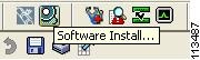
Installing SAN-OS Software Using Fabric Manager
To use the Software Install Wizard to install a new software image using Fabric Manager, follow these steps:
Step 1
Figure 2-1 Software Install Wizard Icon
You see the Software Install Wizard.
Step 2
Step 3
Step 4
Step 5
This screen shows the active (and standby, if applicable) bootflash: memory space on each switch, and shows the status (whether there is enough space for the new images). If any switch has insufficient space, you cannot proceed. Deselect the switch without enough bootflash: memory by going back to the first screen and unchecking the check box for that switch.
Step 6
Step 7
Note
Step 8
Step 9
Note
Note
Installing Cisco SAN-OS Software from the CLI
To perform an automated software upgrade on any switch from the CLI, follow these steps:
Step 1
Step 2
Step 3
The example below demonstrates upgrading from SAN-OS 2.0(2b) to 2.1(1a) using the install all command with the source images located on a SCP server.
Tip
ca-9506# install all system scp://testuser@dino/tftpboot/rel/qa/2_1_1a/final/m9500-sf1ek9-mz.2.1.1a.bin kickstart scp://testuser@dino/tftpboot/rel/qa/2_1_1a/final/m9500-sf1ek9-kickstart-mz.2.1.1a.binFor scp://testuser@dino, please enter password:For scp://testuser@dino, please enter password:Copying image from scp://testuser@dino/tftpboot/rel/qa/2_1_1a/final/m9500-sf1ek9-kickstart-mz.2.1.1a.bin to bootflash:///m9500-sf1ek9-kickstart-mz.2.1.1a.bin.[####################] 100% -- SUCCESSCopying image from scp://testuser@dino/tftpboot/rel/qa/2_1_1a/final/m9500-sf1ek9-mz.2.1.1a.bin to bootflash:///m9500-sf1ek9-mz.2.1.1a.bin.[####################] 100% -- SUCCESSVerifying image bootflash:///m9500-sf1ek9-kickstart-mz.2.1.1a.bin[####################] 100% -- SUCCESSVerifying image bootflash:///m9500-sf1ek9-mz.2.1.1a.bin[####################] 100% -- SUCCESSExtracting "slc" version from image bootflash:///m9500-sf1ek9-mz.2.1.1a.bin.[####################] 100% -- SUCCESSExtracting "ips" version from image bootflash:///m9500-sf1ek9-mz.2.1.1a.bin.[####################] 100% -- SUCCESSExtracting "svclc" version from image bootflash:///m9500-sf1ek9-mz.2.1.1a.bin.[####################] 100% -- SUCCESSExtracting "system" version from image bootflash:///m9500-sf1ek9-mz.2.1.1a.bin.[####################] 100% -- SUCCESSExtracting "kickstart" version from image bootflash:///m9500-sf1ek9-kickstart-mz.2.1.1a.bin.[####################] 100% -- SUCCESSExtracting "loader" version from image bootflash:///m9500-sf1ek9-kickstart-mz.2.1.1a.bin.[####################] 100% -- SUCCESSCompatibility check is done:Module bootable Impact Install-type Reason------ -------- -------------- ------------ ------1 yes non-disruptive rolling2 yes non-disruptive rolling3 yes disruptive rolling Hitless upgrade is not supported4 yes disruptive rolling Hitless upgrade is not supported5 yes non-disruptive reset6 yes non-disruptive resetImages will be upgraded according to following table:Module Image Running-Version New-Version Upg-Required------ ---------- -------------------- -------------------- ------------1 slc 2.0(2b) 2.1(1a) yes1 bios v1.1.0(10/24/03) v1.1.0(10/24/03) no2 slc 2.0(2b) 2.1(1a) yes2 bios v1.1.0(10/24/03) v1.1.0(10/24/03) no3 ips 2.0(2b) 2.1(1a) yes3 bios v1.1.0(10/24/03) v1.1.0(10/24/03) no4 svclc 2.0(2b) 2.1(1a) yes4 svcsb 1.3(5m) 1.3(5m) no4 svcsb 1.3(5m) 1.3(5m) no4 bios v1.1.0(10/24/03) v1.1.0(10/24/03) no5 system 2.0(2b) 2.1(1a) yes5 kickstart 2.0(2b) 2.1(1a) yes5 bios v1.1.0(10/24/03) v1.1.0(10/24/03) no5 loader 1.2(2) 1.2(2) no6 system 2.0(2b) 2.1(1a) yes6 kickstart 2.0(2b) 2.1(1a) yes6 bios v1.1.0(10/24/03) v1.1.0(10/24/03) no6 loader 1.2(2) 1.2(2) noDo you want to continue with the installation (y/n)? [n] yInstall is in progress, please wait.Syncing image bootflash:///m9500-sf1ek9-kickstart-mz.2.1.1a.bin to standby.[####################] 100% -- SUCCESSSyncing image bootflash:///m9500-sf1ek9-mz.2.1.1a.bin to standby.[####################] 100% -- SUCCESSSetting boot variables.[####################] 100% -- SUCCESSPerforming configuration copy.[####################] 100% -- SUCCESSModule 5: Waiting for module online.2005 May 20 15:46:03 ca-9506 %KERN-2-SYSTEM_MSG: mts: HA communication with standby terminated. Please check the standby supervisor.-- SUCCESS"Switching over onto standby".Step 4
If the configuration meets all guidelines when the install all command is issued, all modules (supervisor and switching) are upgraded.
Troubleshooting Cisco SAN-OS Software System Reboots
This section lists possible problems and solutions for software reboots and includes the following topics:
•
•
•
•
•
•
Power On or Switch Reboot Hangs
Symptom Power on or switch reboot hangs.
Table 2-5 Power-on or Switch Reboot Hangs
Power on or switch reboot hangs for dual supervisor configuration.
The bootflash is corrupted.
See the "Recovery for Switches with Dual Supervisor Modules" section.
Power on or switch reboot hangs for single supervisor configuration.
The loader is corrupted.
Interrupt the boot process and reconfigure the BIOS through the console port to load a new kickstart image that updates to BIOS image. See the "Recovery Using BIOS Setup for Supervisor-1" section.
The BIOS is corrupted.
Replace this module. Contact your customer support representative to return the failed module.
The kickstart image is corrupted.
Interrupt the boot process at the >loader prompt. Update the kickstart image. See the "Recovery from the loader> Prompt on Supervisor-2 Modules" section.
Boot parameters are incorrect.
Verify and correct the boot parameters and reboot.
The system image is corrupted.
Interrupt the boot process at the switch#boot prompt. Update the system image. See the "Recovery from the switch(boot)# Prompt" section.
Corrupted Bootflash Recovery
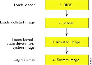
All switch configurations reside in the internal bootflash. If you have a corrupted internal bootflash you could potentially lose your configuration. Be sure to save and back up your configuration files periodically. The regular switch boot goes through the following sequence (see Figure 2-2):
1.
2.
3.
4.
Figure 2-2 Regular Boot Sequence
If the images on your switch are corrupted and you cannot proceed (error state), you can interrupt the switch boot sequence and recover the image by entering the BIOS configuration utility described in the following section. Access this utility only when needed to recover a corrupted internal disk.
Caution
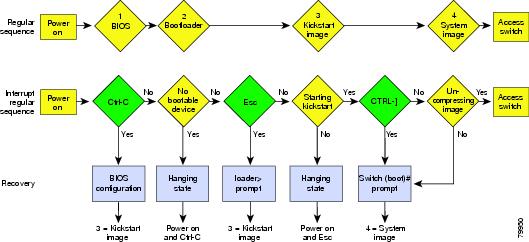
Recovery procedures require the regular sequence to be interrupted. The internal switch sequence goes through four phases between the time you turn on the switch and the time the switch prompt appears on your terminal—BIOS, boot loader, kickstart, and system. (See Table 2-6 and Figure 2-3.)
Table 2-6 Recovery Interruption
BIOS
loader>
No bootable device
The BIOS begins the power-on self test, memory test, and other operating system applications. While the test is in progress, press Ctrl-C to enter the BIOS configuration utility and use the netboot option.
Boot loader
Starting kickstart
loader>
The boot loader uncompresses loaded software to boot an image using its file name as reference. These images are made available through bootflash. When the memory test is over, press Esc to enter the boot loader prompt.
Kickstart
Uncompressing system
switch(boot)#
When the boot loader phase is over, press Ctrl-]3 (Control key plus right bracket key) to enter the switch(boot)# prompt. If the corruption causes the console to stop at this prompt, copy the system image and reboot the switch.
System
Login:
—
The system image loads the configuration file of the last saved running configuration and returns a switch login prompt.
1 This prompt or message appears at the end of each phase.
2 This prompt or message appears when the switch cannot progress to the next phase.
3 Depending on your Telnet client, these keys may be reserved, and you need to remap the keystroke. Refer to the documentation provided by your Telnet client.
Figure 2-3 Regular and Recovery Sequence
Recovery Using BIOS Setup for Supervisor-1
Note
Caution
To recover a corrupted bootflash: device (no bootable device found message) for a switch with a single supervisor-1 module, follow these steps:
Step 1
Step 2
Step 3
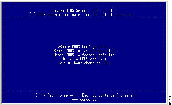
You see the netboot BIOS Setup Utility screen. (See Figure 2-4.)
Figure 2-4 BIOS Setup Utility
Note
Tab = Jump to next field
Ctrl-E = Down arrow
Ctrl-X = Up arrow
Ctrl-H = Erase (Backspace might not work if your terminal is not configured properly.)Step 4
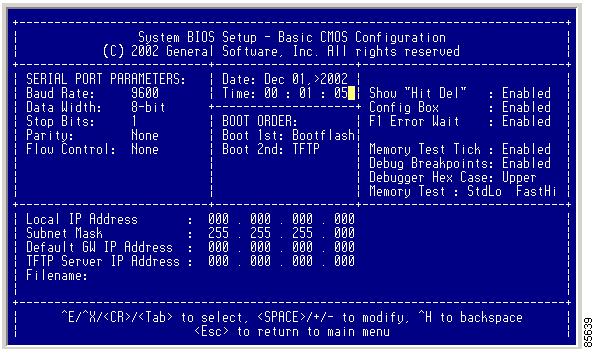
You see the System BIOS Setup - Basic CMOS Configuration screen. (See Figure 2-5.)
Figure 2-5 BIOS Setup Configuration (CMOS)
Step 5
Step 6
Step 7
Step 8
Step 9
Step 10
Step 11
Caution
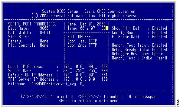
You see the configured changes. (See Figure 2-6.)
Figure 2-6 BIOS Setup Configuration (CMOS) Changes
Step 12
Step 13
Note
Caution
You see the following prompt:
switch(boot)#Step 14
switch(boot)# init system
Note
Caution
Step 15
Recovery from the loader> Prompt on Supervisor-2 Modules
Caution
The loader> prompt is different from the regular switch# prompt.
•
•
•
Tip
To recover a corrupted kickstart image (system error state) for a switch with a single supervisor module, follow these steps:
Step 1
loader> net --ip=172.16.1.2Step 2
loader> net --nm= 255.255.255.0Step 3
loader> net --gw=172.16.1.1Step 4
loader> boot tftp://172.16.10.100/m9500-kickstart-3.0.binIn this example, 172.16.10.100 is the IP address of the TFTP server, and m9500-kickstart-3.0.bin is the name of the kickstart image file that exists on that server.
The switch(boot)# prompt indicates that you have a usable Kickstart image.
Step 5
switch(boot)# init system
Caution
Step 6
Recovery from the loader> Prompt on Supervisor-1 Modules
Caution
The loader> prompt is different from the regular switch# prompt.
•
•
•
Tip
To recover a corrupted kickstart image (system error state) for a switch with a single supervisor module, follow these steps:
Step 1
loader> ip address 172.16.1.2 255.255.255.0Found Intel EtherExpressPro100 82559ER at 0xe800, ROM address 0xc000Probing...[Intel EtherExpressPro100 82559ER]Ethernet addr: 00:05:30:00:52:27Address: 172.16.1.2Netmask: 255.255.255.0Server: 0.0.0.0Gateway: 0.0.0.0Step 2
loader> ip default-gateway 172.16.1.1Address: 172.16.1.2Netmask: 255.255.255.0Server: 0.0.0.0Gateway: 172.16.1.1Step 3
loader> boot tftp://172.16.10.100/kickstart-image1Address: 172.16.1.2Netmask: 255.255.255.0Server: 172.16.10.100Gateway: 172.16.1.1Booting: /kick-282 console=ttyS0,9600n8nn quiet loader_ver= "2.1(2)"................................................Image verification OKStarting kernel...INIT: version 2.78 bootingChecking all filesystems..... done.Loading system softwareINIT: Sending processes the TERM signalSending all processes the TERM signal... done.Sending all processes the KILL signal... done.Entering single-user mode...INIT: Going single userINIT: Sending processes the TERM signalswitch(boot)#The switch(boot)# prompt indicates that you have a usable Kickstart image.
Step 4
switch(boot)# init system
Caution
Step 5
Recovery from the switch(boot)# Prompt
To recover a system image using the kickstart image for a switch with a single supervisor module, follow these steps:
Step 1
switch(boot)#config tswitch(boot)(config)#Step 2
a.
switch(boot)(config)#ip default-gateway 209.165.200.226b.
switch(boot)(config)#interface mgmt 0switch(boot)(config-if)#ip address 209.165.200.227 255.255.255.0Step 3
switch(boot)(config-mgmt0)# no shutdownStep 4
switch(boot)(config-mgmt0)# endStep 5
switch(boot)# init system check-filesytemStep 6
switch(boot)# copy tftp://172.16.10.100/system-image1 bootflash:system-image1Step 7
switch(boot)# copy tftp://172.16.10.100/kickstart-image1 bootflash:kickstart-image1Step 8
switch(boot)# dir bootflash:46080 Nov 11 21:48:55 2008 lost+found/14753280 Nov 11 21:39:49 2008 kickstart-image178473925 Nov 11 21:37:12 2008 system-image1Usage for bootflash://sup-local107465728 bytes used78619648 bytes free186085376 bytes totalStep 9
switch(boot)# load bootflash:system-image1Uncompressing system image: bootflash:/system-image1CCCCCCCCCCCCCCCCCCCCCCCCCCCCCCCCCCCCCCCCCCCCCCCCCWould you like to enter the initial configuration mode? (yes/no): yes
Note
Step 10
switch login:adminPassword:Cisco Storage Area Networking Operating System (SAN-OS) SoftwareTAC support: http://www.cisco.com/tacCopyright (c) 2002-2008, Cisco Systems, Inc. All rights reserved.The copyrights to certain works contained herein are owned byother third parties and are used and distributed under license.Some parts of this software may be covered under the GNU PublicLicense or the GNU Lesser General Public License. A copy ofeach such license is available athttp://www.gnu.org/licenses/gpl.html andhttp://www.gnu.org/licenses/lgpl.htmlswitch#Step 11
switch #config tswitch(config)#boot kickstart bootflash:kickstart-image1switch(config)#boot system bootflash:system-image1switch(config)#endswitch#Step 12
switch# copy running-config startup-config[########################################] 100%switch#
Recovery for Switches with Dual Supervisor Modules
This section describes how to recover when one or both supervisor modules in a dual supervisor switch have corrupted bootflash.
Recovering One Supervisor Module With Corrupted Bootflash
If one supervisor module has functioning bootflash and the other has corrupted bootflash, follow these steps:
Step 1
Step 2
The supervisor module with the corrupted bootflash performs a netboot and checks the bootflash for corruption. When the bootup scripts discover that the bootflash is corrupted, it generates an init system command, which fixes the corrupt bootflash. The supervisor boots as the HA Standby.
Caution
Recovering Both Supervisor Modules With Corrupted Bootflash
If both supervisor modules have corrupted bootflash, follow these steps:
Step 1
Note
00000589K Low Memory Passed
00000000K Ext Memory Passed
Hit ^C if you want to run SETUP....
Wait.....
If you wait too long, you will skip the boot loader phase and enter the kickstart phase.You see the loader> prompt.
Caution
Tip
Step 2
loader> ip address 172.16.1.2 255.255.255.0Found Intel EtherExpressPro100 82559ER at 0xe800, ROM address 0xc000Probing...[Intel EtherExpressPro100 82559ER]Ethernet addr: 00:05:30:00:52:27Address: 172.16.1.2Netmask: 255.255.255.0Server: 0.0.0.0Gateway: 0.0.0.0Step 3
loader> ip default-gateway 172.16.1.1Address: 172.16.1.2Netmask: 255.255.255.0Server: 0.0.0.0Gateway: 172.16.1.1Step 4
loader> boot tftp://172.16.10.100/kickstart-latestAddress: 172.16.1.2Netmask: 255.255.255.0Server: 172.16.10.100Gateway: 172.16.1.1Booting: /kick-282 console=ttyS0,9600n8nn quiet loader_ver= "2.1(2)"................................................Image verification OKStarting kernel...INIT: version 2.78 bootingChecking all filesystems..... done.Loading system softwareINIT: Sending processes the TERM signalSending all processes the TERM signal... done.Sending all processes the KILL signal... done.Entering single-user mode...INIT: Going single userINIT: Sending processes the TERM signalswitch(boot)#The switch(boot)# prompt indicates that you have a usable Kickstart image.
Step 5
Step 6
Step 7
Note
Recognizing Error States
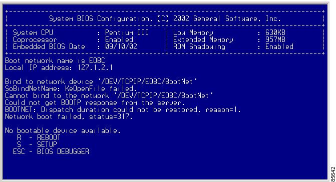
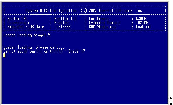
If you see one or both of the error messages displayed in Figure 2-7 or Figure 2-8, follow the procedure specified in the "Recovery Using BIOS Setup for Supervisor-1" section.
Figure 2-7 Error State if Powered On and Ctrl-C Is Entered
Figure 2-8 Error State if Powered On and Esc Is Pressed
Switch or Process Resets
When a recoverable or nonrecoverable error occurs, the switch or a process on the switch may reset.
Symptom The switch or a process on the switch reset.
Table 2-7 Switch or Process Resets
The switch or a process on the switch resets.
A recoverable error occurred on the system or on a process in the system.
Cisco SAN-OS automatically recovered from the problem. See the "Recoverable System Restarts" section and the "Switch or Process Resets" section.
A nonrecoverable error occurred on the system.
Cisco SAN-OS cannot recover automatically from the problem. See the "Unrecoverable System Restarts" section to determine the cause.
A clock module failed.
Verify that a clock module failed. See the "Troubleshooting Clock Module Issues" section on page 4-12. Replace the failed clock module during the next maintenance window.
Recoverable System Restarts
Every process restart generates a syslog message and a Call Home event. Even if the event does not affect service, you should identify and resolve the condition immediately because future occurrences could cause service interruption.
To respond to a recoverable system restart, follow these steps:
Step 1
switch# show log logfile | include errorFor information about the meaning of each message, refer to the Cisco MDS 9000 Family System Messages Reference.
The system output looks like the following example:
Sep 10 23:31:31 dot-6 % LOG_SYSMGR-3-SERVICE_TERMINATED: Service "sensor" (PID 704) has
finished with error code SYSMGR_EXITCODE_SY.
switch# show logging logfile | include failJan 27 04:08:42 88 %LOG_DAEMON-3-SYSTEM_MSG: bind() fd 4, family 2, port 123, addr 0.0.0.0, in_classd=0 flags=1 fails: Address already in useJan 27 04:08:42 88 %LOG_DAEMON-3-SYSTEM_MSG: bind() fd 4, family 2, port 123, addr 127.0.0.1, in_classd=0 flags=0 fails: Address already in useJan 27 04:08:42 88 %LOG_DAEMON-3-SYSTEM_MSG: bind() fd 4, family 2, port 123, addr 127.1.1.1, in_classd=0 flags=1 fails: Address already in useJan 27 04:08:42 88 %LOG_DAEMON-3-SYSTEM_MSG: bind() fd 4, family 2, port 123, addr 172.22.93.88, in_classd=0 flags=1 fails: Address already in useJan 27 23:18:59 88 % LOG_PORT-5-IF_DOWN: Interface fc1/13 is down (Link failureor not-connected)Jan 27 23:18:59 88 % LOG_PORT-5-IF_DOWN: Interface fc1/14 is down (Link failureor not-connected)Jan 28 00:55:12 88 % LOG_PORT-5-IF_DOWN: Interface fc1/1 is down (Link failure or not-connected)Jan 28 00:58:06 88 % LOG_ZONE-2-ZS_MERGE_FAILED: Zone merge failure, Isolating port fc1/1 (VSAN 100)Jan 28 00:58:44 88 % LOG_ZONE-2-ZS_MERGE_FAILED: Zone merge failure, Isolating port fc1/1 (VSAN 100)Jan 28 03:26:38 88 % LOG_ZONE-2-ZS_MERGE_FAILED: Zone merge failure, Isolating port fc1/1 (VSAN 100)Jan 29 19:01:34 88 % LOG_PORT-5-IF_DOWN: Interface fc1/1 is down (Link failure or not-connected)switch#Step 2
switch# show processesThe following codes are used in the system output for the State (process state):
•
•
•
•
•
•
•
Note
The system output looks like the following example. (The output has been abbreviated to be more concise.)
PID State PC Start_cnt TTY Process----- ----- -------- ----------- ---- -------------1 S 2ab8e33e 1 - init2 S 0 1 - keventd3 S 0 1 - ksoftirqd_CPU04 S 0 1 - kswapd5 S 0 1 - bdflush6 S 0 1 - kupdated71 S 0 1 - kjournald136 S 0 1 - kjournald140 S 0 1 - kjournald431 S 2abe333e 1 - httpd443 S 2abfd33e 1 - xinetd446 S 2ac1e33e 1 - sysmgr452 S 2abe91a2 1 - httpd453 S 2abe91a2 1 - httpd456 S 2ac73419 1 S0 vsh469 S 2abe91a2 1 - httpd470 S 2abe91a2 1 - httpdStep 3
switch# show process logProcess PID Normal-exit Stack-trace Core Log-create-time---------------- ------ ----------- ----------- ------- ---------------ntp 919 N N N Jan 27 04:08snsm 972 N Y N Jan 24 20:50Step 4
switch# show processes log pid 898Service: idehsdDescription: ide hotswap handler DaemonStarted at Mon Sep 16 14:56:04 2002 (390923 us)Stopped at Thu Sep 19 14:18:42 2002 (639239 us)Uptime: 2 days 23 hours 22 minutes 22 secondsStart type: SRV_OPTION_RESTART_STATELESS (23)Death reason: SYSMGR_DEATH_REASON_FAILURE_SIGTERM (3)Exit code: signal 15 (no core)CWD: /var/sysmgr/workVirtual Memory:CODE 08048000 - 0804D660DATA 0804E660 - 0804E824BRK 0804E9A0 - 08050000STACK 7FFFFD10Register Set:EBX 00000003 ECX 0804E994 EDX 00000008ESI 00000005 EDI 7FFFFC9C EBP 7FFFFCACEAX 00000008 XDS 0000002B XES 0000002BEAX 00000003 (orig) EIP 2ABF5EF4 XCS 00000023EFL 00000246 ESP 7FFFFC5C XSS 0000002BStack: 128 bytes. ESP 7FFFFC5C, TOP 7FFFFD100x7FFFFC5C: 0804F990 0804C416 00000003 0804E994 ................0x7FFFFC6C: 00000008 0804BF95 2AC451E0 2AAC24A4 .........Q.*.$.*0x7FFFFC7C: 7FFFFD14 2AC2C581 0804E6BC 7FFFFCA8 .......*........0x7FFFFC8C: 7FFFFC94 00000003 00000001 00000003 ................0x7FFFFC9C: 00000001 00000000 00000068 00000000 ........h.......0x7FFFFCAC: 7FFFFCE8 2AB4F819 00000001 7FFFFD14 .......*........0x7FFFFCBC: 7FFFFD1C 0804C470 00000000 7FFFFCE8 ....p...........0x7FFFFCCC: 2AB4F7E9 2AAC1F00 00000001 08048A2C ...*...*....,...PID: 898SAP: 0UUID: 0switch#Step 5
switch# show system uptimeStart Time: Fri Sep 13 12:38:39 2002Up Time: 0 days, 1 hours, 16 minutes, 22 secondsTo determine if the restart is repetitive or a one-time occurrence, compare the length of time that the system has been up with the timestamp of each restart.
Step 6
switch# show coresModule-num Process-name PID Core-create-time---------- ------------ --- ----------------5 fspf 1524 Jan 9 03:116 fcc 919 Jan 9 03:098 acltcam 285 Jan 9 03:098 fib 283 Jan 9 03:08The output shows all cores that are presently available for upload from the active supervisor. The module-num column shows the slot number on which the core was generated. In the previous example, an FSPF core was generated on the active supervisor module in slot 5. An FCC core was generated on the standby supervisory module in slot 6. Core dumps generated on the module in slot 8 include ACLTCAM and FIB.
To copy the FSPF core dump in this example to a TFTP server with the IP address 1.1.1.1, enter the following command:
switch# copy core://5/1524 tftp::/1.1.1.1/abcdThe following command displays the file named zone_server_log.889 in the log directory:
switch# show pro log pid 1473======================================================Service: ipsDescription: IPS ManagerStarted at Tue Jan 8 17:07:42 1980 (757583 us)Stopped at Thu Jan 10 06:16:45 1980 (83451 us)Uptime: 1 days 13 hours 9 minutes 9 secondsStart type: SRV_OPTION_RESTART_STATELESS (23)Death reason: SYSMGR_DEATH_REASON_FAILURE_SIGNAL (2)Exit code: signal 6 (core dumped)CWD: /var/sysmgr/workVirtual Memory:CODE 08048000 - 080FB060DATA 080FC060 - 080FCBA8BRK 081795C0 - 081EC000STACK 7FFFFCF0TOTAL 20952 KBRegister Set:EBX 000005C1 ECX 00000006 EDX 2AD721E0ESI 2AD701A8 EDI 08109308 EBP 7FFFF2ECEAX 00000000 XDS 0000002B XES 0000002BEAX 00000025 (orig) EIP 2AC8CC71 XCS 00000023EFL 00000207 ESP 7FFFF2C0 XSS 0000002BStack: 2608 bytes. ESP 7FFFF2C0, TOP 7FFFFCF00x7FFFF2C0: 2AC8C944 000005C1 00000006 2AC735E2 D..*.........5.*0x7FFFF2D0: 2AC8C92C 2AD721E0 2AAB76F0 00000000 ,..*.!.*.v.*....0x7FFFF2E0: 7FFFF320 2AC8C920 2AC513F8 7FFFF42C ... ..*...*,...0x7FFFF2F0: 2AC8E0BB 00000006 7FFFF320 00000000 ...*.... .......0x7FFFF300: 2AC8DFF8 2AD721E0 08109308 2AC65AFC ...*.!.*.....Z.*0x7FFFF310: 00000393 2AC6A49C 2AC621CC 2AC513F8 .......*.!.*...*0x7FFFF320: 00000020 00000000 00000000 00000000 ...............0x7FFFF330: 00000000 00000000 00000000 00000000 ................0x7FFFF340: 00000000 00000000 00000000 00000000 ................0x7FFFF350: 00000000 00000000 00000000 00000000 ................0x7FFFF360: 00000000 00000000 00000000 00000000 ................0x7FFFF370: 00000000 00000000 00000000 00000000 ................0x7FFFF380: 00000000 00000000 00000000 00000000 ................0x7FFFF390: 00000000 00000000 00000000 00000000 ................0x7FFFF3A0: 00000002 7FFFF3F4 2AAB752D 2AC5154C .... output abbreviated ...Stack: 128 bytes. ESP 7FFFF830, TOP 7FFFFCD0Step 7
system cores tftp:[//servername][/path]
This command causes the switch to enable the automatic copy of core files to a TFTP server. For example, the following command sends the core files to the TFTP server with the IP address 10.1.1.1:
switch(config)# system cores tftp://10.1.1.1/coresThe following conditions apply:
•
•
copy core://module#/pid# tftp://tftp_ip_address/file_name.•
•
Step 8
See also the "Troubleshooting Supervisor Issues" section on page 4-14 or the "Troubleshooting Switching and Services Modules" section on page 4-21.
Unrecoverable System Restarts
An unrecoverable system restart might occur in the following cases:
•
•
•
The effect of a process reset is determined by the policy configured for each process. Unrecoverable reset may cause loss of functionality, restart of the active supervisor, a supervisor switchover, or restart of the switch.
To respond to an unrecoverable reset, see the "Troubleshooting Cisco SAN-OS Software System Reboots" section.
The show system reset-reason CLI command displays the following information:
•
•
•
•
•
•
•
•
Example 2-2 show system reason-reset Command Output
switch# show system reset-reason module 5----- reset reason for module 5 -----1) At 224801 usecs after Fri Jan 21 16:36:40 2005Reason: Reset Requested by CLI command reloadService:Version: 2.1(2)2) At 922828 usecs after Fri Jan 21 16:02:48 2005Reason: Reset Requested by CLI command reloadService:Version: 2.1(2)3) At 318034 usecs after Fri Jan 21 14:03:36 2005Reason: Reset Requested by CLI command reloadService:Version:2.1(2)4) At 255842 usecs after Wed Jan 19 00:07:49 2005Reason: Reset Requested by CLI command reloadService:Version: 2.1(2)Recovering the Administrator Password
You can access the switch if you forget the administrator password by following the directions in Table 2-8.
Symptom You forgot the administrator password for accessing a switch.
Table 2-8 Recovering Administrator Password
You forgot the administrator password for accessing a Cisco MDS 9000 Family switch.
You can recover the password using a local console connection. For the latest instructions on password recovery, refer to the Cisco MDS 9000 CLI Family Configuration Guide at the following website:
http://cisco.com/en/US/products/ps5989/products_installation_and_configuration_guides_list.html
If you can access Device Manager, recover the administrator password by following these steps:
Step 1
"username admin password 0 admin123"Step 2
Note
Step 3
Step 4
Miscellaneous Software Image Issues
This section includes software image issues reported by the relevant release notes and includes the following topics:
•
•
•
•
All Ports Down Because of System Health Failure
Symptom Console reports all ports on a module are down because of a system health failure.
Switch Reboots after FCIP Reload
Symptom Switch rebooted after FCIP module was reloaded, upgraded, or downgraded.
FCIP Link Fails to Come Up
Symptom A newly configured FCIP link may fail to come up when running on an MPS-14/2 module.
Cannot Create, Modify, or Delete Admin Role
Symptom Cannot create, modify, or delete the admin role.
FC IDs Change after Link Reset
Symptom FC IDs change after a link resets.
Switch Displays Wrong User
Symptom Switch displays the wrong user with the show running-config CLI command.