Initial Configuration

Table Of Contents

Initial Configuration

Starting a Switch in the Cisco MDS 9000 Family

Initial Setup Routine

Preparing to Configure the Switch

Default Login

Setup Options

Assigning Setup Information

Configuring Out-of-Band Management

Configuring In-Band Management

Using the setup Command

Accessing the Switch

Assigning a Switch Name

Where Do You Go Next?

Verifying the Module Status

Configuring Date, Time, and Time Zone

Configuring the Time Zone

Adjusting for Daylight Saving Time or Summer Time

NTP Configuration

About NTP

NTP Configuration Guidelines

Configuring NTP

NTP CFS Distribution

Enabling NTP Distribution

Committing NTP Configuration Changes

Discarding NTP Configuration Changes

Releasing Fabric Session Lock

Database Merge Guidelines

NTP Session Status Verification

Management Interface Configuration

Obtaining Remote Management Access

Using the force Option During Shutdown

Default Gateway Configuration

Configuring the Default Gateway

Telnet Server Connection

Disabling a Telnet Connection

Configuring Console Port Settings

Verifying Console Port Settings

Configuring COM1 Port Settings

Verifying COM1 Port Settings

Configuring Modem Connections

Guidelines to Configure Modems

Enabling Modem Connections

Configuring the Initialization String

Configuring the Default Initialization String

Configuring a User-Specified Initialization String

Initializing a Modem in a Powered-On Switch

Verifying the Modem Connection Configuration

Configuring CDP

Clearing CDP Counters and Tables

Displaying CDP Information


Initial Configuration


This chapter includes the following sections:

Starting a Switch in the Cisco MDS 9000 Family

Initial Setup Routine

Accessing the Switch

Assigning a Switch Name

Where Do You Go Next?

Verifying the Module Status

Configuring Date, Time, and Time Zone

NTP Configuration

Management Interface Configuration

Default Gateway Configuration

Telnet Server Connection

Configuring Console Port Settings

Configuring COM1 Port Settings

Configuring Modem Connections

Configuring CDP

Starting a Switch in the Cisco MDS 9000 Family

The following procedure is a review of the tasks you should have completed during hardware installation, including starting up the switch. These tasks must be completed before you can configure the switch.

Before you can configure a switch, follow these steps:


Step 1 Verify the following physical connections for the new Cisco MDS 9000 Family switch:

The console port is physically connected to a computer terminal (or terminal server).

The management 10/100/1000 Ethernet port (mgmt0) is connected to an external hub, switch, or router.

Refer to the Cisco MDS 9000 Family Hardware Installation Guide (for the required product) for more information.


Tip Save the host ID information for future use (for example, to enable licensed features). The host ID information is provided in the Proof of Purchase document that accompanies the switch.


Step 2 Verify that the default console port parameters are identical to those of the computer terminal (or terminal server) attached to the switch console port:

9600 baud

8 data bits

1 stop bit

No parity


Note On Cisco terminal servers, issue the following commands starting in EXEC mode:
switch# config t
switch(config)# line 1
switch(config)# no flush-at-activation
switch(config)# line 1
switch(config)# exit
switch# copy running-config startup-config
This configuration ensures that the MDS switch does not receive random characters that might cause it to hang.


Step 3 Power on the switch. The switch boots automatically and the switch# prompt appears in your terminal window.


Initial Setup Routine

The first time that you access a switch in the Cisco MDS 9000 Family, it runs a setup program that prompts you for the IP address and other configuration information necessary for the switch to communicate over the supervisor module Ethernet interface. This information is required to configure and manage the switch.


Note The IP address can only be configured from the CLI. When you power up the switch for the first time assign the IP address. After you perform this step, the Cisco MDS 9000 Family Fabric Manager can reach the switch through the console port.


Preparing to Configure the Switch

Before you configure a switch in the Cisco MDS 9000 Family for the first time, you need the following information:

Administrator password, including:

Creating a password for the administrator (required).

Creating an additional login account and password (optional).


Note If a password is trivial (short, easy-to-decipher), your password configuration is rejected. Be sure to configure a strong password. You must configure a password that meets the requirements listed in the "Characteristics of Strong Passwords" section on page 39-11.


IPv4 address or IPv6 address for the switch management interface—The management interface can be an out-of-band Ethernet interface or an in-band Fibre Channel interface (recommended).

If you are using an IPv4 address for the management interface, you need the following information:

IPv4 subnet mask for the switch's management interface (optional).

Destination IPv4 prefix, destination IPv4 prefix subnet mask, and next hop IPv4 address, if you want to enable IP routing.

IPv4 address of the default gateway (optional).

SSH service on the switch—To enable this optional service, select the type of SSH key (dsa/rsa/rsa1) and number of key bits (768 to 2048).

DNS IPv4 address or IPv6 address (optional).

Default domain name (optional).

NTP server IPv4 address or IPv6 address (optional).

SNMP community string (optional).

Switch name—This is your switch prompt (optional).


Note If you are using IPv4, be sure to configure the IPv4 route, the IPv4 default network address, and the IPv4 default gateway address to enable SNMP access. If IP routing is enabled, the switch uses the IPv4 route and the default network IPv4 address. If IP routing is disabled, the switch uses the default gateway IPv4 address.


Default Login

All Cisco MDS 9000 Family switches have the network administrator as a default user (admin). You cannot change the default user at any time (see the "Role-Based Authorization" section on page 39-1).

There is no default password so you must explicitly configure a strong password. If a password is trivial (short, easy-to-decipher), your password configuration is rejected. Be sure to configure a strong password (see the ). If you configure and subsequently forget this new password, you have the option to recover this password (see the "Recovering the Administrator Password" section on page 39-19).


Note The Cisco Fabric Switch for IBM BladeCenter does not use admin as the default user. Rather, the default user is USERID because there is no console access to the switch. You cannot delete the user USERID on this switch. The password for this default user is PASSW0RD, where the "0" is a zero. You can change this password; however, a write erase operation restores the default password. There is no initial setup menu.

Also note that you should not bring up the loader> prompt; the only way to fix this condition is to RMA the switch.

The following commands are not allowed on the Cisco Fabric Switch for IBM BladeCenter: write erase boot and init system; nor can you boot variables manually.


Note If you issue a write erase command and reload the switch, you must reconfigure the default user (admin) password using the setup procedure.


Setup Options

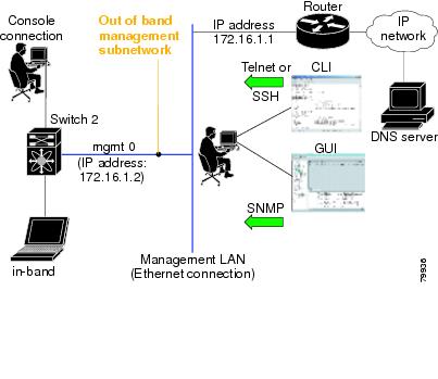
The setup scenario differs based on the subnet to which you are adding the new switch. You must configure a Cisco MDS 9000 Family switch with an IP address to enable management connections from outside of the switch.


Note Some concepts such as out-of-band management and in-band management are briefly explained here. These concepts are explained in more detail in subsequent chapters.


Out-of-band management—This feature provides a connection to the network through a supervisor module front panel Ethernet port (see Figure 5-1).

In-band management—This feature provides IP over Fibre Channel (IPFC) to manage the switches. The in-band management feature is transparent to the network management system (NMS). Instead of conventional Ethernet physical media, switches in the Cisco MDS 9000 Family use IPFC as the transport mechanism (see Figure 5-1 and Chapter 43, "Configuring IP Services").

Figure 5-1 Management Access to Switches

Assigning Setup Information

This section describes how to initially configure the switch for both out-of-band and in-band management.


Note Press Ctrl-C at any prompt to skip the remaining configuration options and proceed with what is configured until that point. Entering the new password for the administrator is a requirement and cannot be skipped. See the "Characteristics of Strong Passwords" section on page 39-11.


Tip If you do not wish to answer a previously configured question, or if you wish to skip answers to any questions, press Enter. If a default answer is not available (for example, switch name), the switch uses what was previously configured and skips to the next question.


Note The setup script only supports IPv4 for the management interface. For information on configuring IPv6 on the management interface, see the Chapter 46, "Configuring IPv6 for Gigabit Ethernet Interfaces."


Configuring Out-of-Band Management


Note You can configure both in-band and out-of-band configuration together by entering Yes in both Step 11c and Step 11d in the following procedure.


To configure the switch for first time out-of-band access, follow these steps:


Step 1 Power on the switch. Switches in the Cisco MDS 9000 Family boot automatically.

Step 2 Enter the new password for the administrator.

Enter the password for admin: 2004AsdfLkjh18 

Tip If a password is trivial (short, easy-to-decipher), your password configuration is rejected. Be sure to configure a strong password as shown in the sample configuration. Passwords are case-sensitive. You must explicitly configure a password that meets the requirements listed in the "Characteristics of Strong Passwords" section on page 39-11.


Step 3 Enter yes to enter the setup mode.

This setup utility will guide you through the basic configuration of the system. Setup 
configures only enough connectivity for management of the system.

Please register Cisco MDS 9000 Family devices promptly with your supplier. Failure to 
register may affect response times for initial service calls. MDS devices must be 
registered to receive entitled support services.

Press Enter incase you want to skip any dialog. Use ctrl-c at anytime to skip away 
remaining dialogs.

Would you like to enter the basic configuration dialog (yes/no): yes

The setup utility guides you through the basic configuration process. Press Ctrl-C at any prompt to end the configuration process.

Step 4 Enter the new password for the administrator (admin is the default).

Enter the password for admin: admin 

Step 5 Enter yes (no is the default) to create additional accounts.

Create another login account (yes/no) [n]: yes

While configuring your initial setup, you can create an additional user account (in the network-admin role) besides the administrator's account. See the "Role-Based Authorization" section on page 39-1 for information on default roles and permissions.


Note User login IDs must contain non-numeric characters.


a. Enter the user login ID.

Enter the user login ID: user_name

b. Enter the user password.

Enter the password for user_name: user-password

Step 6 Enter yes (yes is the default) to create an SNMPv3 account.

Configure SNMPv3 Management parameters (yes/no) [y]: yes

a. Enter the user name (admin is the default).

SNMPv3 user name [admin]: admin

b. Enter the SNMPv3 password (minimum of eight characters). The default is admin123.

SNMPv3 user authentication password: admin_pass


Note By default, if the admin password is at least eight characters, then the SNMP authentication password is the same as the admin password (at least eight characters). If the admin password is less than eight characters, then you need to provide a new password for SNMP. The admin password can have a minimum of one character, but the SNMP authentication password must have a minimum of eight characters.


Step 7 Enter yes (no is the default) to configure the read-only or read-write SNMP community string.

Configure read-only SNMP community string (yes/no) [n]: yes

a. Enter the SNMP community string.

SNMP community string: snmp_community

Step 8 Enter a name for the switch.


Note The switch name is limited to 32 alphanumeric characters. The default is switch.


Enter the switch name: switch_name

Step 9 Enter yes (yes is the default) to configure out-of-band management.

Continue with Out-of-band (mgmt0) management configuration? [yes/no]: yes

a. Enter the mgmt0 IPv4 address.

Mgmt0 IPv4 address: ip_address

b. Enter the mgmt0 IPv4 subnet mask.

Mgmt0 IPv4 netmask: subnet_mask

Step 10 Enter yes (yes is the default) to configure the IPv4 default gateway (recommended).

Configure the default-gateway: (yes/no) [y]: yes 

a. Enter the default gateway IPv4 address.

IPv4 address of the default-gateway: default_gateway

Step 11 Enter yes (no is the default) to configure advanced IP options such as in-band management, static routes, default network, DNS, and domain name.

Configure Advanced IP options (yes/no)? [n]: yes

a. Enter no (no is the default) at the in-band management configuration prompt.

Continue with in-band (VSAN1) management configuration? (yes/no) [no]: no

b. Enter yes (yes is the default) to enable IPv4 routing capabilities.

Enable the ip routing? (yes/no) [y]: yes 

c. Enter yes (yes is the default) to configure a static route (recommended).

Configure static route: (yes/no) [y]: yes 

Enter the destination prefix.

Destination prefix: dest_prefix 

Type the destination prefix mask.

Destination prefix mask: dest_mask 

Type the next hop IP address.

Next hop ip address: next_hop_address 


Note Be sure to configure the IP route, the default network IP address, and the default gateway IP address to enable SNMP access. If IP routing is enabled, the switch uses the IP route and the default network IP address. If IP routing is disabled, the switch uses the default gateway IP address.


d. Enter yes (yes is the default) to configure the default network (recommended).

Configure the default network: (yes/no) [y]: yes 

Enter the default network IPv4 address.


Note The default network IPv4 address is the destination prefix provided in Step 11c .


Default network IP address [dest_prefix]: dest_prefix 

e. Enter yes (yes is the default) to configure the DNS IPv4 address.

Configure the DNS IP address? (yes/no) [y]: yes

Enter the DNS IP address.

DNS IP address: name_server

f. Enter yes (default is no) to configure the default domain name.

Configure the default domain name? (yes/no) [n]: yes

Enter the default domain name.

Default domain name: domain_name

Step 12 Enter yes (yes is the default) to enable the Telnet service.

Enable the telnet service? (yes/no) [y]: yes

Step 13 Enter yes (no is the default) to enable the SSH service.

Enabled SSH service? (yes/no) [n]: yes

Step 14 Enter the SSH key type (see the "Overwriting a Generated Key-Pair" section on page 39-16) that you would like to generate.

Type the SSH key you would like to generate (dsa/rsa/rsa1)? dsa

Step 15 Enter the number of key bits within the specified range.

Enter the number of key bits? (768 to 2048): 768

Step 16 Enter yes (no is the default) to configure the NTP server.

Configure NTP server? (yes/no) [n]: yes

a. Enter the NTP server IPv4 address.

NTP server IP address: ntp_server_IP_address

Step 17 Enter shut (shut is the default) to configure the default switch port interface to the shut (disabled) state.

Configure default switchport interface state (shut/noshut) [shut]: shut


Note The management ethernet interface is not shut down at this point—only the Fibre Channel, iSCSI, FCIP, and Gigabit Ethernet interfaces are shut down.


Step 18 Enter on (on is the default) to configure the switch port trunk mode.

Configure default switchport trunk mode (on/off/auto) [on]: on

Step 19 Enter yes (yes is the default) to configure the switchport mode F.

Configure default switchport mode F (yes/no) [n]: y

Step 20 Enter on (off is the default) to configure the PortChannel auto-create state.

Configure default port-channel auto-create state (on/off) [off]: on

Step 21 Enter permit (deny is the default) to deny a default zone policy configuration.

Configure default zone policy (permit/deny) [deny]: permit

Permits traffic flow to all members of the default zone.


Note If you are executing the setup script after issuing a write erase command, you explicitly must change the default zone policy to permit for VSAN 1 after finishing the script using the following commands:
switch# config t
switch(config)# zone default-zone permit vsan 1


Step 22 Enter yes (no is the default) to enable a full zone set distribution (see the "Zone Set Distribution" section on page 23-13).

Enable full zoneset distribution (yes/no) [n]: yes 

Overrides the switch-wide default for the full zone set distribution feature.

You see the new configuration. Review and edit the configuration that you have just entered.

Step 23 Enter no (no is the default) if you are satisfied with the configuration.

The following configuration will be applied:
  username admin password admin_pass role network-admin
  username user_name password user_pass role network-admin
  snmp-server community snmp_community ro
  switchname switch
  interface mgmt0
    ip address ip_address subnet_mask
    no shutdown
  ip routing
  ip route dest_prefix dest_mask dest_address
  ip default-network dest_prefix
  ip default-gateway default_gateway
  ip name-server name_server
  ip domain-name domain_name
  telnet server enable
  ssh key dsa 768 force
  ssh server enable
  ntp server ipaddr ntp_server
  system default switchport shutdown
  system default switchport trunk mode on
  system default switchport mode F
  system default port-channel auto-create
  zone default-zone permit vsan 1-4093
  zoneset distribute full vsan 1-4093
Would you like to edit the configuration? (yes/no) [n]: no

Step 24 Enter yes (yes is default) to use and save this configuration:

Use this configuration and save it? (yes/no) [y]: yes


Caution If you do not save the configuration at this point, none of your changes are updated the next time the switch is rebooted. Type yes to save the new configuration. This ensures that the kickstart and system images are also automatically configured (see Chapter 7, "Software Images").

Configuring In-Band Management

The in-band management logical interface is VSAN 1. This management interface uses the Fibre Channel infrastructure to transport IP traffic. An interface for VSAN 1 is created on every switch in the fabric. Each switch should have its VSAN 1 interface configured with either an IPv4 address or an IPv6 address in the same subnetwork. A default route that points to the switch providing access to the IP network should be configured on every switch in the Fibre Channel fabric (see Chapter 19, "Configuring and Managing VSANs").


Note You can configure both in-band and out-of-band configuration together by entering Yes in both Step 9c and Step 9d in the following procedure.


To configure a switch for first time in-band access, follow these steps:


Step 1 Power on the switch. Switches in the Cisco MDS 9000 Family boot automatically.

Step 2 Enter the new password for the administrator.

Enter the password for admin: 2004asdf*lkjh18 


Tip If a password is trivial (short, easy-to-decipher), your password configuration is rejected. Be sure to configure a strong password as shown in the sample configuration. Passwords are case-sensitive. You must explicitly configure a password that meets the requirements listed in the "Characteristics of Strong Passwords" section on page 39-11.


Step 3 Enter yes to enter the setup mode.

This setup utility will guide you through the basic configuration of the system. Setup 
configures only enough connectivity for management of the system.

Please register Cisco MDS 9000 Family devices promptly with your supplier. Failure to 
register may affect response times for initial service calls. MDS devices must be 
registered to receive entitled support services.

Press Enter incase you want to skip any dialog. Use ctrl-c at anytime to skip away 
remaining dialogs.

Would you like to enter the basic configuration dialog (yes/no): yes

The setup utility guides you through the basic configuration process. Press Ctrl-C at any prompt to end the configuration process.

Step 4 Enter no (no is the default) if you do not wish to create additional accounts.

Create another login account (yes/no) [no]: no

Step 5 Configure the read-only or read-write SNMP community string.

a. Enter no (no is the default) to avoid configuring the read-only SNMP community string.

Configure read-only SNMP community string (yes/no) [n]: no

b. Enter no (no is the default) to configure the read-only SNMP community string.

Configure read-only SNMP community string (yes/no) [n]: yes

c. Enter the SNMP community string.

SNMP community string: snmp_community

Step 6 Enter a name for the switch.


Note The switch name is limited to 32 alphanumeric characters. The default is switch.


Enter the switch name: switch_name

Step 7 Enter no (yes is the default) at the configuration prompt to configure out-of-band management.

Continue with Out-of-band (mgmt0) management configuration? [yes/no]: no

Step 8 Enter yes (yes is the default) to configure the default gateway.

Configure the default-gateway: (yes/no) [y]: yes 

a. Enter the default gateway IP address.

IP address of the default gateway: default_gateway

Step 9 Enter yes (no is the default) to configure advanced IP options such as in-band management, static routes, default network, DNS, and domain name.

Configure Advanced IP options (yes/no)? [n]: yes

a. Enter yes (no is the default) at the in-band management configuration prompt.

Continue with in-band (VSAN1) management configuration? (yes/no) [no]: yes

Enter the VSAN 1 IPv4 address.

VSAN1 IPv4 address: ip_address

Enter the IPv4 subnet mask.

VSAN1 IPv4 net mask: subnet_mask

b. Enter no (yes is the default) to enable IPv4 routing capabilities.

Enable ip routing capabilities? (yes/no) [y]: no

c. Enter no (yes is the default) to configure a static route.

Configure static route: (yes/no) [y]: no 

d. Enter no (yes is the default) to configure the default network.

Configure the default-network: (yes/no) [y]: no 

e. Enter no (yes is the default) to configure the DNS IPv4 address.

Configure the DNS IP address? (yes/no) [y]: no

f. Enter no (no is the default) to skip the default domain name configuration.

Configure the default domain name? (yes/no) [n]: no

Step 10 Enter no (yes is the default) to disable the Telnet service.

Enable the telnet service? (yes/no) [y]: no

Step 11 Enter yes (no is the default) to enable the SSH service.

Enabled SSH service? (yes/no) [n]: yes

Step 12 Enter the SSH key type (see the "Overwriting a Generated Key Pair" section on page 39-17that you would like to generate.

Type the SSH key you would like to generate (dsa/rsa/rsa1)? rsa

Step 13 Enter the number of key bits within the specified range.

Enter the number of key bits? (768 to 1024): 1024

Step 14 Enter no (no is the default) to configure the NTP server.

Configure NTP server? (yes/no) [n]: no

Step 15 Enter shut (shut is the default) to configure the default switch port interface to the shut (disabled) state.

Configure default switchport interface state (shut/noshut) [shut]: shut


Note The management Ethernet interface is not shut down at this point—only the Fibre Channel, iSCSI, FCIP, and Gigabit Ethernet interfaces are shut down.


Step 16 Enter auto (off is the default) to configure the switch port trunk mode.

Configure default switchport trunk mode (on/off/auto) [off]: auto

Step 17 Enter yes (yes is the default) to configure the switchport mode F.

Configure default switchport mode F (yes/no) [n]: y

Step 18 Enter off (off is the default) to configure the PortChannel auto-create state.

Configure default port-channel auto-create state (on/off) [off]: off

Step 19 Enter deny (deny is the default) to deny a default zone policy configuration.

Configure default zone policy (permit/deny) [deny]: deny

Denies traffic flow to all members of the default zone.

Step 20 Enter no (no is the default) to disable a full zone set distribution (see the "Zone Set Distribution" section on page 23-13).

Enable full zoneset distribution (yes/no) [n]: no 

Disables the switch-wide default for the full zone set distribution feature.

You see the new configuration. Review and edit the configuration that you have just entered.

Step 21 Enter no (no is the default) if you are satisfied with the configuration.

The following configuration will be applied:
  username admin password admin_pass role network-admin
  snmp-server community snmp_community rw
  switchname switch
  interface vsan1
    ip address ip_address subnet_mask
    no shutdown
  ip default-gateway default_gateway
  no telnet server enable
  ssh key rsa 1024 force
  ssh server enable
  system default switchport shutdown
  system default switchport trunk mode auto
  system default switchport mode F
  no zone default-zone permit vsan 1-4093
  no zoneset distribute full vsan 1-4093
Would you like to edit the configuration? (yes/no) [n]: no

Step 22 Enter yes (yes is default) to use and save this configuration.

Use this configuration and save it? (yes/no) [y]: yes


Caution If you do not save the configuration at this point, none of your changes are updated the next time the switch is rebooted. Type yes to save the new configuration. This ensures that the kickstart and system images are also automatically configured (see Chapter 7, "Software Images").

Using the setup Command

To make changes to the initial configuration at a later time, you can issue the setup command in EXEC mode.

switch# setup
---- Basic System Configuration Dialog ----
This setup utility will guide you through the basic configuration of
the system. Setup configures only enough connectivity for management
of the system.
*Note: setup always assumes a predefined defaults irrespective
of the current system configuration when invoked from CLI.

Press Enter incase you want to skip any dialog. Use ctrl-c at anytime
to skip away remaining dialogs.

Would you like to enter the basic configuration dialog (yes/no): yes

The setup utility guides you through the basic configuration process.

Accessing the Switch

After initial configuration, you can access the switch in one of three ways (see Figure 5-2):

Serial console access—You can use a serial port connection to access the CLI.

In-band IP (IPFC) access—You can use Telnet or SSH to access a switch in the Cisco MDS 9000 Family or use SNMP to connect to a Cisco MDS 9000 Fabric Manager application.

Out-of-band (10/100/1000 BASE-T Ethernet) access—You can use Telnet or SSH to access a switch in the Cisco MDS 9000 Family or use SNMP to connect to a Cisco MDS 9000 Fabric Manager application. Supervisor-1 modules support 10/100 BASE-T Ethernet and Supervisor-2 modules support 10/100/1000 BASE-T Ethernet.


Note To use the Cisco Fabric Manager, refer to the Cisco MDS 9000 Family Fabric Manager Configuration Guide.


Figure 5-2 Switch Access Options

Assigning a Switch Name

Each switch in the fabric requires a unique name. You can assign names to easily identify the switch by its physical location, its SAN association, or the organization to which it is deployed. The assigned name is displayed in the command-line prompt. The switch name is limited to 20 alphanumeric characters.


Note This guide refers to a switch in the Cisco MDS 9000 Family as switch, and it uses the switch# prompt.


To change the name of the switch, follow these steps:

 
Command
Purpose

Step 1 

switch# config t

Enters configuration mode.

Step 2 

switch(config)# switchname myswitch1

myswitch1(config)#

Changes the switch name prompt as specified (myswitch1).

Step 3 

myswitch1(config)# no switchname

switch(config)#

Reverts the switch name prompt to its default (switch#).

Where Do You Go Next?

After reviewing the default configuration, you can change it or perform other configuration or management tasks. The initial setup can only be performed at the CLI. However, you can continue to configure other software features, or access the switch after initial configuration by using either the CLI or the Device Manager and Fabric Manager applications.

To use the Cisco Fabric Manager, refer to the Cisco MDS 9000 Family Fabric Manager Configuration Guide.

Verifying the Module Status

Before you begin configuring the switch, you need to ensure that the modules in the chassis are functioning as designed.

To verify the status of a module at any time, issue the show module command in EXEC mode. A sample output of the show module command follows:

switch# show module
Mod  Ports  Module-Type                     Model              Status
---  -----  ------------------------------- ------------------ ------------
2    8      IP Storage Services Module      DS-X9308-SMIP      ok
5    0      Supervisor/Fabric-1             DS-X9530-SF1-K9    active *
6    0      Supervisor/Fabric-1             DS-X9530-SF1-K9    ha-standby
8    0      Caching Services Module         DS-X9560-SMAP      ok
9    32     1/2 Gbps FC Module              DS-X9032           ok

Mod  Sw           Hw      World-Wide-Name(s) (WWN)
---  -----------  ------  --------------------------------------------------
2    1.3(0.106a)  0.206   20:41:00:05:30:00:00:00 to 20:48:00:05:30:00:00:00
5    1.3(0.106a)  0.602   --
6    1.3(0.106a)) 0.602   -- 
8    1.3(0.106a)  0.702   --
9    1.3(0.106a)  0.3     22:01:00:05:30:00:00:00 to 22:20:00:05:30:00:00:00


Mod  MAC-Address(es)                         Serial-Num
---  --------------------------------------  ----------
2    00-05-30-00-9d-d2 to 00-05-30-00-9d-de  JAB064605a2
5    00-05-30-00-64-be to 00-05-30-00-64-c2  JAB06350B1R
6    00-d0-97-38-b3-f9 to 00-d0-97-38-b3-fd  JAB06350B1R
8    00-05-30-01-37-7a to 00-05-30-01-37-fe  JAB072705ja
9    00-05-30-00-2d-e2 to 00-05-30-00-2d-e6  JAB06280ae9

* this terminal session

If the status is OK or active, you can continue with your configuration (see Chapter 11, "Managing Modules").


Configuring Date, Time, and Time Zone

Switches in the Cisco MDS 9000 Family use Universal Coordinated Time (UTC), which is the same as Greenwich Mean Time (GMT).

To change the default time on the switch, issue the clock command from EXEC mode.

switch# clock set <HH:MM:SS> <DD> <Month in words> <YYYY>

For example:

switch# clock set 15:58:09 23 September 2002 
Mon Sep 23 15:58:09 UTC 2002

Where HH represents hours in military format (15 for 3 p.m.), MM is minutes (58), SS is seconds (09), DD is the date (23), Month is the month in words (September), and YYYY is the year (2002).


Note The date and time changes are saved across system resets.


Configuring the Time Zone

You can specify a time zone for the switch.

To specify the local time without the daylight saving time feature, follow these steps:

 
Command
Purpose

Step 1 

switch# config t

Enters configuration mode.

Step 2 

switch(config)# clock timezone <timezone name> <-23 to 23 hours offset from UTC time> <0 to 50 minutes offset from UTC>


Example:

switch(config)# clock timezone PST -8 0

Sets the time zone with a specified name, specified hours, and specified minutes.

This example sets the time zone to Pacific Standard Time (PST) and offsets the UTC time by negative eight hours and 0 minutes.

Step 3 

switch(config)# exit

switch#

Returns to EXEC mode.

Step 4 

switch# show clock

Verifies the time zone configuration.

Step 5 

switch# show run

Displays changes made to the time zone configuration along with other configuration information.

Adjusting for Daylight Saving Time or Summer Time

You can configure your switch to adjust for daylight saving time (or summer time). By default, MDS SAN-OS does not automatically adjust for daylight saving time. You must manually configure the switch to adjust to the daylight saving time.

For example, following U.S. standards, you can have the switch advance the clock one hour at 2:00 a.m. on the first Sunday in April and move back the clock one hour at 2:00 a.m. on the last Sunday in October. You can also explicitly specify the start and end dates and times and whether or not the time adjustment recurs every year.


Note To enable the daylight saving time clock adjustment, follow these steps:

 
Command
Purpose

Step 1 

switch# config t

switch(config)#

Enters configuration mode.

Step 2 

switch(config)# clock timezone timezone_name hour_offset_from_UTC minute_offset_from_UTC


Example:

switch(config)# clock timezone PST -8 0

Offsets the time zone as specified.


This example sets the U.S. Pacific standard offset time as negative 8 hours and 0 minutes.

switch(config)# no clock timezone

Disables the time zone adjustment feature.

Step 3 

switch(config)# clock summer-time daylight_timezone_name start_week start_day start_month start_time end_week end_day end_month end_time daylight_offset_inminutes


Example:

switch(config)# clock summer-time PDT 2 Sunday March 02:00 1 Sunday November 02:00 60

switch(config)#

Sets the daylight savings time for a specified time zone.

The start and end values are as follows:

Week ranging from 1 through 5

Day ranging from Sunday through Saturday

Month ranging from January through December

The daylight offset ranges from 1 through 1440 minutes, which are added to the start time and deleted time from the end time.

This example adjusts the daylight savings time for the U.S. Pacific daylight time by 60 minutes starting the second Sunday in March at 2 a.m. and ending the first Sunday in November at 2 a.m.

switch(config)# no clock summer-time

Disables the daylight saving time adjustment feature.

Step 4 

switch(config)# exit

switch#

Returns to EXEC mode.

Step 5 

switch# show running-config | include summer-time

Verifies the time zone configuration. If summer-time is not part of the running configuration, then the switch is not configured for daylight savings time.

In 2007, the U. S. the daylight saving time adjustment occurs on the second Sunday in March and end on the first Sunday in November. You can update the configuration of your switch to accommodate this change using the following command:

switch(config)# clock summer-time daylight_timezone_name 2 Sunday March 02:00 1 Sunday November 02:00 60


Note CFS does not support daylight savings time because a single fabric can span multiple time zones; every switch must be configured individually.


If you want to configure daylight savings time on multiple switches simultaneously, see the RUN CLI command feature in the Cisco MDS 9000 Family Fabric Manager Configuration Guide.

NTP Configuration

A Network Time Protocol (NTP) server provides a precise time source (radio clock or atomic clock) to synchronize the system clocks of network devices. NTP is transported over User Datagram Protocol UDP/IP. All NTP communications use Universal Time Coordinated (UTC). An NTP server receives its time from a reference time source, such as a radio clock or atomic clock, attached to the time. NTP distributes this time across the network.

This section includes the following sections:

About NTP

NTP Configuration Guidelines

Configuring NTP

NTP CFS Distribution

About NTP

In a large enterprise network, having one time standard for all network devices is critical for management reporting and event logging functions when trying to correlate interacting events logged across multiple devices. Many enterprise customers with extremely mission-critical networks maintain their own stratum-1 NTP source.

Time synchronization happens when several frames are exchanged between clients and servers. The switches in client mode know the address of one or more NTP servers. The servers act as the time source and receive client synchronization requests.

By configuring an IP address as a peer, the switch will obtain and provide time as required. The peer is capable of providing time on its own and is capable of having a server configured. If both these instances point to different time servers, your NTP service is more reliable. Thus, even if the active server link is lost, you can still maintain the right time due to the presence of the peer.


Tip If an active server fails, a configured peer helps in providing the NTP time. Provide a direct NTP server association and configure a peer to ensure backup support if the active server fails.


If you only configure a peer, the most accurate peer takes on the role of the NTP server and the other peer(s) acts as a peer(s). Both machines end at the right time if they have the right time source or if they point to the right NTP source.

NTP Configuration Guidelines

The following guidelines apply to all NTP configurations:

You should have a peer association with another switch only when you are sure that your clock is reliable (which means that you are a client of a reliable NTP server).

A peer configured alone takes on the role of a server and should be used as backup. If you have two servers, then you can have several switches point to one server, and the remaining switches to the other server. Then you would configure peer association between these two sets. This forces the clock to be more reliable.

If you only have one server, it's better for all the switches to have a client association with that server.

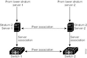
Not even a server down time will affect well-configured switches in the network. Figure 5-3 displays a network with two NTP stratum 2 servers and two switches.

Figure 5-3 NTP Peer and Server Association  

In this configuration, the switches were configured as follows:

Stratum 2 Server 1

IPv4 address-10.10.10.10

Stratum-2 Server-2

IPv4 address-10.10.10.9

Switch 1 IPv4 address-10.10.10.1

Switch 1 NTP configuration

NTP server 10.10.10.10

NTP peer 10.10.10.2

Switch 2 IPv4 address-10.10.10.2

Switch 2 NTP configuration

NTP server 10.10.10.9

NTP peer 10.10.10.1

Configuring NTP

You can configure NTP using either IPv4 addresses, IPv6 addresses, or DNS names.

To configure NTP in a server association using IPv4 addresses, follow these steps:

 
Command
Purpose

Step 1 

switch# config t

Enters configuration mode.

Step 2 

switch(config)# ntp server 10.10.10.10

Forms a server association with a server.

Step 3 

switch(config)# ntp peer 10.20.10.0

Forms a peer association with a peer. You can specify multiple associations.

Step 4 

switch(config)# exit

switch#

Returns to EXEC mode.

Step 5 

switch# copy running-config startup-config

Saves your configuration changes to NVRAM.

Tip This is one instance where you can save the configuration as a result of an NTP configuration change. You can issue this command at any time.

Step 6 

switch# show ntp peers

--------------------------------------------

Peer IP Address Serv/Peer

--------------------------------------------

10.20.10.0 Peer (configured)

10.10.10.10 Server (configured)

Displays the configured server and peer associations.

Note A domain name is resolved only when you have a DNS server configured.

To configure NTP in a server association using IPv6 addresses, follow these steps:

 
Command
Purpose

Step 1 

switch# config t

Enters configuration mode.

Step 2 

switch(config)# ntp server 2001:db8:800:200c::4101

Forms a server association with a server.

Step 3 

switch(config)# ntp peer 2001:db8:800:200c::417a

Forms a peer association with a peer. You can specify multiple associations.

Step 4 

switch(config)# exit

switch#

Returns to EXEC mode.

Step 5 

switch# copy running-config startup-config

Saves your configuration changes to NVRAM.

Tip This is one instance where you can save the configuration as a result of an NTP configuration change. You can issue this command at any time.

Step 6 

switch# show ntp peers

-----------------------------------------------

Peer IP Address Serv/Peer

-----------------------------------------------

2001:db8:800:200c::417a Peer (configured)

2001:db8:800:200c::4101 Server (configured)

Displays the configured server and peer associations.

Note A domain name is resolved only when you have a DNS server configured.

To configure NTP in a server association using DNS names, follow these steps:

 
Command
Purpose

Step 1 

switch# config t

Enters configuration mode.

Step 2 

switch(config)# ntp server NtpServer

Forms a server association with a server.

Step 3 

switch(config)# ntp peer NtpPeer

Forms a peer association with a peer. You can specify multiple associations.

Step 4 

switch(config)# exit

switch#

Returns to EXEC mode.

Step 5 

switch# copy running-config startup-config

Saves your configuration changes to NVRAM.

Tip This is one instance where you can save the configuration as a result of an NTP configuration change. You can issue this command at any time.

Step 6 

switch# show ntp peers

--------------------------------------------

Peer IP Address Serv/Peer

--------------------------------------------

NtpPeer Peer (configured)

NtpServer Server (configured)

Displays the configured server and peer associations.

NTP CFS Distribution

You can enable NTP fabric distribution for all Cisco MDS switches in the fabric. When you perform NTP configurations, and distribution is enabled, the entire server/peer configuration is distributed to all the switches in the fabric.

You automatically acquire a fabric-wide lock when you issue the first configuration command after you enabled distribution in a switch. The NTP application uses the effective and pending database model to store or commit the commands based on your configuration.

See to Chapter 6, "Using the CFS Infrastructure," for more information on the CFS application.

This section includes the following sections:

Enabling NTP Distribution

Committing NTP Configuration Changes

Releasing Fabric Session Lock

Database Merge Guidelines

NTP Session Status Verification

Enabling NTP Distribution

To enable NTP configuration fabric distribution, follow these steps:

 
Command
Purpose

Step 1 

switch# config t

Enters configuration mode.

Step 2 

switch(config)# ntp distribute

Enables NTP configuration distribution to all switches in the fabric. Acquires a fabric lock and stores all future configuration changes in the pending database.

switch(config)# no ntp distribute

Disables (default) NTP configuration distribution to all switches in the fabric.

Committing NTP Configuration Changes

When you commit the NTP configuration changes, the effective database is overwritten by the configuration changes in the pending database and all the switches in the fabric receive the same configuration. When you commit the NTP configuration changes without implementing the session feature, the NTP configurations are distributed to all the switches in the fabric.

To commit the NTP configuration changes, follow these steps:

 
Command
Purpose

Step 1 

switch# config t

Enters configuration mode.

Step 2 

switch(config)# ntp commit

Distributes the NTP configuration changes to all switches in the fabric and releases the lock. Overwrites the effective database with the changes made to the pending database.

Discarding NTP Configuration Changes

After making the configuration changes, you can choose to discard the changes or to commit them. In either case, the lock is released.

To discard NTP configuration changes, follow these steps:

 
Command
Purpose

Step 1 

switch# config t

Enters configuration mode.

Step 2 

switch(config)# ntp abort

Discards the NTP configuration changes in the pending database and releases the fabric lock.

Releasing Fabric Session Lock

If you have performed an NTP fabric task and have forgotten to release the lock by either committing or discarding the changes, an administrator can release the lock from any switch in the fabric. If the administrator performs this task, your changes to the pending database are discarded and the fabric lock is released.


Tip The changes are only available in the volatile directory and are subject to being discarded if the switch is restarted.


To use administrative privileges and release a locked NTP session, use the clear ntp session command.

switch# clear ntp session

Database Merge Guidelines

When merging two fabrics, follow these guidelines:

Be aware that the merge is a union of the existing and the received database in each switch in the fabric.

Do not configure an IP address as a server on one switch and as a peer on another switch. The merge can fail if this configuration exists.

Verify that the union of the databases does not exceed the maximum limit of 64.

See to the "CFS Merge Support" section on page 6-8 for detailed concepts.

NTP Session Status Verification

To verify the status of the NTP session, use the show ntp session-status command.

switch# show ntp session-status
last-action : Distribution Enable    Result : Success

Management Interface Configuration

The management interface on the switch allows multiple simultaneous Telnet or SNMP sessions. You can remotely configure the switch through the management interface (mgmt0), but first you must configure some IP parameters so that the switch is reachable. You can manually configure the management interface from the CLI. You can configure the mgmt 0 interface with either IPv4 address parameters or an IPv6 address.

On director class switches, a single IP address is used to manage the switch. The active supervisor module's mgmt0 interface uses this IP address. The mgmt0 interface on the standby supervisor module remains in an inactive state and cannot be accessed until a switchover happens. After a switchover, the mgmt0 interface on the standby supervisor module becomes active and assumes the same IP address as the previously active supervisor module.

The management port (mgmt0) is autosensing and operates in full duplex mode at a speed of 10/100/1000 Mbps (1000 Mbps is only available on the Supervisor-2 module). Autosensing supports both the speed and the duplex mode. On a Supervisor-1 module, the default speed is 100 Mbps and the default duplex mode is auto. On a Supervisor-2 module, the default speed is auto and the default duplex mode is auto.


Note Before you begin to configure the management interface manually, obtain the switch's IPv4 address and IPv4 subnet mask or the IPv6 address. Also make sure the console cable is connected to the console port.


Obtaining Remote Management Access

In some cases, a switch interface might be administratively shut down. You can check the status of an interface at any time by using the show interface mgmt 0 command.

To obtain remote management access using IPv4 addressing parameters, follow these steps:

 
Command
Command

Step 1 

switch# config terminal

switch(config)#

Enters configuration mode. You can also abbreviate the command to config t.

Step 2 

switch(config)# interface mgmt 0

switch(config-if)#

Enters the interface configuration mode on the specified interface (mgmt0).

You can use the console interface on the switch to configure the management Ethernet interface.

Step 3 

switch(config-if)# ip address 1.1.1.0 255.255.255.0

Specifies the IPv4 address and IPv4 subnet mask.

Step 4 

switch(config-if)# switchport speed 100

Configures the port speed in Mbps. Valid values are 10, 100, and 1000 (Supervisor-2 module only).

Step 5 

switch(config-if)# no shutdown

Enables the interface.

Step 6 

switch(config-if)# exit

Returns to configuration mode.

Step 7 

switch(config)# ip default-gateway 1.1.1.1

Configures the IPv4 default gateway address.

To obtain remote management access using IPv6 addressing parameters, follow these steps:

 
Command
Command

Step 1 

switch# config terminal

switch(config)#

Enters configuration mode. You can also abbreviate the command to config t.

Step 2 

switch(config)# interface mgmt 0

switch(config-if)#

Enters the interface configuration mode on the specified interface (mgmt0).

You can use the console interface on the switch to configure the management Ethernet interface.

Step 3 

switch(config-if)# ipv6 address 2001:0DB8:800:200C::417A/64

Specifies the IPv6 address and prefix length.

switch(config-if)# ipv6 address autoconfig

Specifies IPv6 autoconfiguration.

Step 4 

switch(config-if)# switchport speed 100

Configures the port speed in Mbps. Valid values are 10, 100, and 1000 (Supervisor-2 module only).

Step 5 

switch(config-if)# no shutdown

Enables the interface.

Step 6 

switch(config-if)# exit

switch(config)#

Returns to configuration mode.

Using the force Option During Shutdown

When you try to shut down a management interface (mgmt0), a follow-up message confirms your action before performing the operation. You can use the force option to bypass this confirmation. The following example shuts down the interface without using the force option:

switch# config t
switch(config)# interface mgmt 0
switch(config-if)# shutdown
Shutting down this interface will drop all telnet sessions.
Do you wish to continue (y/n)? y

The following example shuts down the interface using the force option:

switch# config t
switch(config)# interface mgmt 0
switch(config-if)# shutdown force


Note You need to explicitly configure a default gateway to connect to the switch and send IP packets or add a route for each subnet.


Default Gateway Configuration

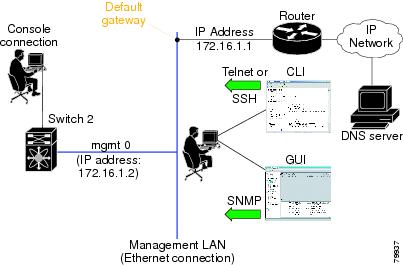
The supervisor module sends IP packets with unresolved destination IPv4 addresses to the default gateway (see Figure 5-4).

Figure 5-4 Default Gateway

Configuring the Default Gateway

To configure the IPv4 address of the default gateway, follow these steps:

 
Command
Purpose

Step 1 

switch# config t

Enters configuration mode.

Step 2 

switch(config)# ip default-gateway 172.16.1.1

Configures the 172.16.1.1 IPv4 address.

Telnet Server Connection

The Telnet server is enabled by default on all switches in the Cisco MDS 9000 Family. If you require a secure SSH connection, you need to disable the default Telnet connection and then enable the SSH connection (see the "Generating the SSH Server Key Pair" section on page 39-16).


Note For information on connecting a terminal to the supervisor module console port, refer to the Cisco MDS 9200 Series Hardware Installation Guide or the Cisco MDS 9500 Series Hardware Installation Guide.


Tip A maximum of 16 sessions are allowed in any switch in the Cisco MDS 9500 Series or the Cisco MDS 9200 Series.


Make sure the terminal is connected to the switch and that the switch and terminal are both powered on.

Disabling a Telnet Connection

To disable Telnet connections to the switch, follow these steps:

 
Command
Purpose

Step 1 

switch# config t

Enters configuration mode.

Step 2 

switch(config)# no telnet server enable

updated

Disables the Telnet server.

switch(config)# telnet server enable

updated

Enables (default) the Telnet server to return a Telnet connection from a secure SSH connection.

Configuring Console Port Settings

The console port is an asynchronous serial port that enables switches in the Cisco MDS 9000 Family to be set up for initial configuration through a standard RS-232 port with an RJ-45 connector. Any device connected to this port must be capable of asynchronous transmission. Connection to a terminal requires a terminal emulator to be configured as 9600 baud, 8 data bits, 1 stop bit, no parity.


Caution The console baud rate automatically reverts to the default rate (9600) after any BIOS upgrade.

To configure the console port parameters from the console terminal, follow these steps:

 
Command
Command

Step 1 

switch# config terminal

switch(config)#

Enters configuration mode.

Step 2 

switch(config)# line console

switch(config-console)#

Enters the line console configuration mode.

Step 3 

switch(config-console)# speed 9600

Configures the port speed for the serial console. The default console baud rate is 9600 baud. The valid values for Supervisor-1 modules are between 110 and 115200 bps (110, 150, 300, 600, 1200, 2400, 4800, 9600, 19200, 28800, 38400, 57600, 115200). The valid values for Supervisor-2 modules are 9600, 19200, 38400, and 115200. Be sure to specify one of these exact values.

Step 4 

switch(config-console)# databits 8

Configures the data bits for the console connection. The default is 8 data bits and the valid range is between 5 and 8 data bits.

Step 5 

switch(config-console)# stopbits 1

Configures the stop bits for the console connection. The default is 1 stop bit and the valid values are 1 or 2 stop bits.

Step 6 

switch(config-console)# parity none

Configures the parity for the console connection. The default is no parity and the valid values are even or odd parity.

Verifying Console Port Settings

Use the show line console command to verify the configured console settings. This command also displays problems that may have occurred along with the other registration statistics.

The following example displays output from an MDS switch with a Supervisor-1 module.

switch# show line console
line Console:
    Speed:        9600 bauds
    Databits:     8 bits per byte
    Stopbits:     1 bit(s)
    Parity:       none
    Modem In: Enable
    Modem Init-String -
        default : ATQ0V1H0S0=1\015
    Statistics:  tx:12842     rx:366     Register Bits:RTS|CTS|DTR|DSR|CD|RI

The following example displays output from an MDS switch with a Supervisor-2 module.

switch# show line console
line Console:
    Speed:        9600 bauds
    Databits:     8 bits per byte
    Stopbits:     1 bit(s)
    Parity:       none
    Modem In: Enable
    Modem Init-String -
        default : ATE0Q0V1&D0&C0S0=1\015
    Statistics:  tx:12842     rx:366     Register Bits:RTS|CTS|DTR|DSR|CD|RI

Configuring COM1 Port Settings

A COM1 port is an RS-232 port with a DB-9 interface that enables you to connect to an external serial communication device such as a modem. Connection to a terminal requires the terminal emulator to be configured as 9600 baud, 8 data bits, 1 stop bit, no parity.

To configure the COM1 port settings, follow these steps:

 
Command
Description

Step 1 

switch# config terminal

switch(config)#

Enters configuration mode.

Step 2 

switch(config)# line com1

switch(config-com1)#

Enters the COM1 port configuration mode.

Step 3 

switch(config-com1)# speed 9600

Configures the port speed for the COM1 connection. The default console baud rate is 9600 baud. The valid range is between 110 and 115,200 bps (110, 150, 300, 600, 1200, 2400, 4800, 9600, 19200, 28800, 38400, 57600, 115200). Be sure to specify one of these exact values.

Note This configuration depends on the incoming speed of the modem connected to COM1.

Step 4 

switch(config-com1)# databits 8

Configures the data bits for the COM1 connection. The default is 8 data bits and the valid range is between 5 and 8 data bits.

Step 5 

switch(config-com1)# stopbits 1

Configures the stop bits for the COM1 connection. The default is 1 stop bits and the valid values are 1 or 2 stop bits.

Step 6 

switch(config-com1)# parity none

Configures the parity for the COM1 connection. The default is no parity and the valid values are even or odd parity.

Step 7 

switch(config-com1)# no flowcontrol hardware

Disables hardware flow control. By default, hardware flow control is enabled on all switches in the Cisco 9000 Family. When enabled, this option is useful in protecting data loss at higher baud rates.

Note This option is only available through the COM1 port.

Verifying COM1 Port Settings

Use the show line com1 command to verify the configured COM1 settings. This command also displays problems that may have occurred along with the other registration statistics.

The following example displays output from an MDS switch with a Supervisor-1 module.

switch# show line com1
line Aux:
    Speed:        9600 bauds
    Databits:     8 bits per byte
    Stopbits:     1 bit(s)
    Parity:       none
    Modem In: Enable
    Modem Init-String -
        default : ATQ0V1H0S0=1\015
    Statistics:  tx:17     rx:0     Register Bits:RTS|DTR

The following example displays output from an MDS switch with a Supervisor-2 module.

switch# show line com1
line Aux:
    Speed:        9600 bauds
    Databits:     8 bits per byte
    Stopbits:     1 bit(s)
    Parity:       none
    Modem In: Enable
    Modem Init-String -
        default : ATE0Q0V1&D0&C0S0=1\015
    Statistics:  tx:17     rx:0     Register Bits:RTS|DTR

Configuring Modem Connections

Modems can only be configured if you are connected to the console or COM1 ports. A modem connection to a switch in the Cisco MDS 9000 Family does not affect switch functionality.


Note If you plan on connecting a modem to the console port or the COM1 port of a switch in the Cisco MDS 9000 Family, refer to the Cisco MDS 9500 Series Hardware Installation Guide or the Cisco MDS 9200 Series Hardware Installation Guide. COM1 ports are not available on switches in the Cisco MDS 9100 Series. Refer to the Cisco MDS 9100 Series Hardware Installation Guide.


Guidelines to Configure Modems


Tip We recommend you use the COM1 port to connect the modem from any director in the Cisco MDS 9500 Series or any switch in the Cisco MDS 9200 Series.


The following guidelines apply to modem configurations:

The following modems were tested to work in the Cisco SAN-OS environment using Supervisor-1 modules:

MultiTech MT2834BA (http://www.multitech.com/PRODUCTS/Families/MultiModemII/)

Hayes Accura V.92 (http://www.hayesmicro.com/Products/accura-prod-v92.htm)

The following modems were tested to work in the Cisco SAN-OS environment using Supervisor-2 modules:

Hayes Accura V.92 (http://www.hayesmicro.com/Products/accura-prod-v92.htm)

Zoom/FaxModem 56K Dualmode Model 2949 (http://www.zoom.com/products/dial_up_external_serial.html)

Multitech MT2834 BA 33.6K (http://www.multitech.com/PRODUCTS/Families/CC1600-Series/)


Note On the Multitech MT2834 BA 33.6K set the DIP switch1 (pin1), also known as the DTR-pin, to the DOWN position to enable the DTR signal (or set it to ON). You must connect the modem before attempting to configure it.


USRobotics Model 5686 V.92 (http://www.usr.com/products/home/home-product.asp?sku=USR5686E)


Note On the USRobotics Model 5686 V.92 set the DIP switch1 (pin1), also known as the DTR-pin, to the DOWN position to enable the DTR signal (or set it to ON). You must connect the modem before attempting to configure it.


Do not connect a modem to the console port while the system is booting.

Follow the procedure specified in the "Initializing a Modem in a Powered-On Switch" section.

Enabling Modem Connections

To configure a modem connection through the COM1 port, follow these steps:

 
Command
Command

Step 1 

switch# config t

switch(config)#

Enters configuration mode.

Step 2 

switch(config)# line com1

switch(config-com1)#

Enters the COM1 port configuration mode.

Step 3 

switch(config-com1)# modem in

Enables the COM1 port to only connect to a modem.

switch(config-com1)# no modem in

Disables (default) the current modem from executing its functions.

To configure a modem connection through the console port, follow these steps:

 
Command
Command

Step 1 

switch# config t

switch(config)#

Enters configuration mode.

Step 2 

switch(config)# line console

switch(config-console)#

Enters the console port configuration mode.

Step 3 

switch(config-console)# modem in

Enables the console port to only connect to a modem.

switch(config-console)# no modem in

Disables (default) the current modem from executing its functions.

Configuring the Initialization String

Switches in the Cisco MDS 9500 Series and the Cisco MDS 9200 Series have a default initialization string (ATE0Q1&D2&C1S0=1\015) to detect connected modems. The default string detects connected modems supported by Cisco Systems. The default string contents for Supervisor-1 modules are as follows:

AT—Attention

E0 (required)—No echo

Q1—Result code on

&D2—Normal data terminal ready (DTR) option

&C1—Enable tracking the state of the data carrier

S0=1—Pick up after one ring

\015 (required)—Carriage return in octal

The default string contents for Supervisor-2 modules are as follows:

AT—Attention

E0 (required)—No echo

Q0—Result code on

V1—Display result codes as text

&D0—Data terminal ready (DTR) on

&C0—Data carrier detect (DCD) on

S0=1—Pick up after one ring

You may retain the default string or change it to another string (80 character limit) using the user-input option. This option is provided if you prefer to use a modem that is not supported or tested by Cisco systems. If you change the string, the changes you make are permanent and remain in effect unless you change them again. Rebooting the system or restarting the CLI does not change the modem initialization string. The switch is not affected even if the modem is not functioning.


Tip We recommend you use the default initialization string. If the required options are not provided in the user-input string, the initialization string is not processed.


The modem initialization string usage depends on the modem state when the switch boots:

If the modem is already attached to the switch during boot-up, the default initialization string is written to the modem (see the "Configuring the Default Initialization String" section).

If the modem is not attached to the switch during boot-up, then attach the modem as outlined in the Cisco MDS 9000 Family Hardware Installation Guide (depending on the product), and follow the procedure provided in this section (see the "Configuring a User-Specified Initialization String" section).


Note You can perform the configuration specified in this section only if you are connected to the console port or the COM1 port.


Configuring the Default Initialization String

To configure the default initialization string through the COM1 port, follow these steps:

 
Command
Command

Step 1 

switch# config t

switch(config)#

Enters configuration mode.

Step 2 

switch(config)# line com1

switch(config-com1)#

Enters the COM1 port configuration mode.

Step 3 

switch(config-com1)# modem init-string default

Writes the default initialization string to the modem.

To configure the default initialization string through the console port, follow these steps:

 
Command
Command

Step 1 

switch# config t

switch(config)#

Enters configuration mode.

Step 2 

switch(config)# line com1

switch(config-console)#

Enters the console port configuration mode.

Step 3 

switch(config-console)# modem init-string default

Writes the default initialization string to the modem.

Configuring a User-Specified Initialization String

To configure a user-specified initialization string through the COM1 port, follow these steps:

 
Command
Command

Step 1 

switch# config terminal

switch(config)#

Enters configuration mode.

Step 2 

switch(config)# line com1

switch(config-com1)#

Enters the COM1 port configuration mode.

Step 3 

switch(config-com1)# modem set-string user-input ATE0Q1&D2&C1S0=3\015

Assigns the user-specified initialization string for a Supervisor-1 module to its corresponding profile.

Note You must first set the user-input string before initializing the string.

switch(config-com1)# modem set-string user-input ATE0Q0V1&D0&C0S0=1

Assigns the user-specified initialization string for a Supervisor-2 module to its corresponding profile.

switch(config-com1)# no modem set-string

Reverts the configured initialization string to the factory default string.

Step 4 

switch(config-com1)# modem init-string user-input

Writes the user-specified initialization string to the modem.

To configure a user-specified initialization string through the console port, follow these steps:

 
Command
Command

Step 1 

switch# config terminal

switch(config)#

Enters configuration mode.

Step 2 

switch(config)# line com1

switch(config-console)#

Enters the console port configuration mode.

Step 3 

switch(config-console)# modem set-string user-input ATE0Q1&D2&C1S0=3\015

Assigns the user-specified initialization string to its corresponding profile.

Note You must first set the user-input string before initializing the string.

switch(config-com1)# modem set-string user-input ATE0Q0V1&D0&C0S0=1

Assigns the user-specified initialization string for a Supervisor-2 module to its corresponding profile.

switch(config-com1)# no modem set-string

Reverts the configured initialization string to the factory default string.

Step 4 

switch(config-console)# modem init-string user-input

Writes the user-specified initialization string to the modem.

Initializing a Modem in a Powered-On Switch

When a switch is already powered-on and the modem is later connected to either the console port or the COM1 port, you can initialize the modem using the modem connect line command in EXEC mode. You can specify the com1 option if the modem is connected to the COM1 port, or the console option if the modem is connected to the console.

To connect a modem to a switch that is already powered on, follow these steps.


Step 1 Wait until the system has completed the boot sequence and the system image is running.

Step 2 Connect the modem to the switch as specified in the Cisco MDS 9500 Series Hardware Guide or the Cisco MDS 9200 Series Hardware Installation Guide.

Step 3 Initialize the modem using the modem connect line command in EXEC mode.


Verifying the Modem Connection Configuration

Use the show line command to verify the configured modem settings.

The following example displays output from an MDS switch with a Supervisor-1 module.

switch# show line 
line Console:
    Speed:        9600 bauds
    Databits:     8 bits per byte
    Stopbits:     1 bit(s)
    Parity:       none
    Modem In: Enable
    Modem Init-String -
        default : ATE0Q1&D2&C1S0=1\015
    Statistics:  tx:12842     rx:366     Register Bits:RTS|CTS|DTR|DSR|CD|RI
line Aux:
    Speed:        9600 bauds
    Databits:     8 bits per byte
    Stopbits:     1 bit(s)
    Parity:       none
    Modem In: Enable
    Modem Init-String -
        default : ATE0Q1&D2&C1S0=1\015
    Statistics:  tx:17     rx:0     Register Bits:RTS|DTR

The following example displays output from an MDS switch with a Supervisor-2 module.

switch# show line 
line Console:
    Speed:        9600 bauds
    Databits:     8 bits per byte
    Stopbits:     1 bit(s)
    Parity:       none
    Modem In: Enable
    Modem Init-String -
        default : ATE0Q0V1&D0&C0S0=1
    Statistics:  tx:12842     rx:366     Register Bits:RTS|CTS|DTR|DSR|CD|RI
line Aux:
    Speed:        9600 bauds
    Databits:     8 bits per byte
    Stopbits:     1 bit(s)
    Parity:       none
    Modem In: Enable
    Modem Init-String -
        default : ATE0Q0V1&D0&C0S0=1
    Statistics:  tx:17     rx:0     Register Bits:RTS|DTR

Configuring CDP

The Cisco Discovery Protocol (CDP) is an advertisement protocol used by Cisco devices to advertise itself to other Cisco devices in the same network. CDP runs on the data link layer and is independent of Layer 3 protocols. Cisco devices that receive the CDP packets cache the information to make it is accessible through the CLI and SNMP.

CDP is supported on the management Ethernet interface on the supervisor module and the Gigabit Ethernet interfaces on the IPS and MPS-14/2 modules. The CDP daemon is restartable and switchable. The running and startup configurations are available across restarts and switchovers.

CDP version 1 (v1) and version 2 (v2) are supported in Cisco MDS 9000 Family switches. CDP packets with any other version number are silently discarded when received.

When the interface link is established, CDP is enabled by default and three CDP packets are sent at one-second intervals. Following this, the CDP frames are sent at the globally configured refresh interval.

To globally disable the CDP, follow these steps:

 
Command
Command

Step 1 

switch# config terminal

switch(config)#

Enters configuration mode.

Step 2 

switch(config)# no cdp enable

Operation in progress. Please check global parameters

switch(config-console)#

Disables the CDP protocol on the switch. When CDP is disabled on an interface, one packet is sent to clear out the switch state with each of the receiving devices.

switch(config)# cdp enable

Operation in progress. Please check global parameters

switch(config)#

Enables (default) the CDP protocol on the switch. When CDP is enabled on an interface, one packet is sent immediately. Subsequent packets are sent at the configured refresh time.

To disable the CDP protocol on a specific interface, follow these steps:

 
Command
Command

Step 1 

switch# config terminal

switch(config)#

Enters configuration mode.

Step 2 

switch(config)# interface gigbitethernet 3/8

switch(config-if)#

Configures the Gigabit Ethernet interface for the module in slot 3 port 8.

Step 3 

switch(config-if)# no cdp enable

Operation in progress. Please check interface parameters

switch(config-console)#

Disables the CDP protocol on the selected interface. When CDP is disabled on an interface, one packet is sent to clear out the switch state with each of the receiving devices.

switch(config-if)# cdp enable

Operation in progress. Please check interface parameters

switch(config)#

Enables (default) the CDP protocol on the selected interface. When CDP is enabled on an interface, one packet is sent immediately. Subsequent packets are sent at the configured refresh time.

To globally configure the refresh time interval for the CDP protocol, follow these steps:

 
Command
Command

Step 1 

switch# config terminal

switch(config)#

Enters configuration mode.

Step 2 

switch(config)# cdp timer 100

switch(config)#

Sets the refresh time interval in seconds. The default is 60 seconds and the valid range is from 5 to 255 seconds.

switch(config)# no cdp timer 100

switch(config)#

Reverts the refresh time interval to the factory default of 60 seconds.

To globally configure the hold time advertised in CDP packets, follow these steps:

 
Command
Command

Step 1 

switch# config terminal

switch(config)#

Enters configuration mode.

Step 2 

switch(config)# cdp holdtime 200

Sets the hold time advertised in CDP packets in seconds. The default is 180 seconds and the valid range is from 10 to 255 seconds.

switch(config)# no cdp holdtime 200

Reverts the hold time to the factory default of 180 seconds.

To globally configure the CDP version, follow these steps:

 
Command
Command

Step 1 

switch# config terminal

switch(config)#

Enters configuration mode.

Step 2 

switch(config)# cdp advertise v1

Sets the CDP version to be used. The default is version 2 (v2). The valid options are v1 and v2.

switch(config)# no advertise v1

Reverts the version to the factory default of v2.

Clearing CDP Counters and Tables

Use the clear cdp counters command to clear CDP traffic counters for all interfaces. You can issue this command for a specified interface or for all interfaces (management and Gigabit Ethernet interfaces).

switch# clear cdp counters

Use the clear cdp table command to clear neighboring CDP entries for all interfaces. You can issue this command for a specified interface or for all interfaces (management and Gigabit Ethernet interfaces).

switch# clear cdp table interface gigabitethernet 4/1

Displaying CDP Information

Use the show cdp command to display CDP entries. See Examples 5-1 to 5-11.

Example 5-1 Displays All CDP Capable Interfaces and Parameters

switch# show cdp all
GigabitEthernet4/1 is up
    CDP enabled on interface
    Sending CDP packets every 60 seconds
    Holdtime is 180 seconds
GigabitEthernet4/8 is down
    CDP enabled on interface
    Sending CDP packets every 60 seconds
    Holdtime is 180 seconds
mgmt0 is up
    CDP enabled on interface
    Sending CDP packets every 100 seconds
    Holdtime is 200 seconds

Example 5-2 Displays All CDP Neighbor Entries

switch# show cdp entry all
----------------------------------------
Device ID:069038747(Kiowa3)
Entry address(es):
    IP Address: 172.22.92.5
Platform: WS-C5500, Capabilities: Trans-Bridge Switch
Interface: mgmt0, Port ID (outgoing port): 5/22
Holdtime: 136 sec

Version:
WS-C5500 Software, Version McpSW: 2.4(3) NmpSW: 2.4(3)
Copyright (c) 1995-1997 by Cisco Systems

Advertisement Version: 1

Example 5-3 Displays the Specified CDP Neighbor

switch# show cdp entry name 0
----------------------------------------
Device ID:0
Entry address(es):
    IP Address: 0.0.0.0
Platform: DS-X9530-SF1-K9, Capabilities: Host
Interface: GigabitEthernet4/1, Port ID (outgoing port): GigabitEthernet4/1
Holdtime: 144 sec

Version:
1.1(0.144)

Advertisement Version: 2
Duplex: full

Example 5-4 Displays Global CDP Parameters

switch# show cdp global
Global CDP information:
    CDP enabled globally
    Sending CDP packets every 60 seconds
    Sending a holdtime value of 180 seconds
    Sending CDPv2 advertisements is enabled

Example 5-5 Displays CDP Parameters for the Management Interface

switch# show cdp interface mgmt 0
mgmt0 is up
    CDP enabled on interface
    Sending CDP packets every 60 seconds
    Holdtime is 180 seconds

Example 5-6 Displays CDP Parameters for the Gigabit Ethernet Interface

switch# show cdp interface gigabitethernet 4/1
GigabitEthernet4/1 is up
    CDP enabled on interface
    Sending CDP packets every 80 seconds
    Holdtime is 200 seconds

Example 5-7 Displays CDP Neighbors (in brief)

switch# show cdp neighbors
Capability Codes: R - Router, T - Trans-Bridge, B - Source-Route-Bridge
                  S - Switch, H - Host, I - IGMP, r - Repeater

Device ID        Local Intrfce   Hldtme  Capability  Platform      Port ID
0                Gig4/1          135     H           DS-X9530-SF1- Gig4/1
069038732(Kiowa2 mgmt0           132     T S         WS-C5500      3/3/11
069038747(Kiowa3 mgmt0           156     T S         WS-C5500      6/20
069038747(Kiowa3 mgmt0           158     T S         WS-C5500      5/22

Example 5-8 Displays CDP Neighbors (in detail)

switch# show CDP neighbor detail
----------------------------------------
Device ID:0
Entry address(es):
    IP Address: 0.0.0.0
Platform: DS-X9530-SF1-K9, Capabilities: Host
Interface: GigabitEthernet4/1, Port ID (outgoing port): GigabitEthernet4/1
Holdtime: 162 sec

Version:
1.1(0.144)

Advertisement Version: 2
Duplex: full
----------------------------------------
Device ID:069038732(Kiowa2)
Entry address(es):
    IP Address: 172.22.91.5
Platform: WS-C5500, Capabilities: Trans-Bridge Switch
Interface: mgmt0, Port ID (outgoing port): 3/11
Holdtime: 132 sec

Version:
WS-C5500 Software, Version McpSW: 2.4(3) NmpSW: 2.4(3)
Copyright (c) 1995-1997 by Cisco Systems
Advertisement Version: 1

Example 5-9 Displays the Specified CDP Neighbor (in detail)

switch# show CDP neighbors interface gigabitethernet 4/1 detail
----------------------------------------
Device ID:0
Entry address(es):
    IP Address: 0.0.0.0
Platform: DS-X9530-SF1-K9, Capabilities: Host
Interface: GigabitEthernet4/1, Port ID (outgoing port): GigabitEthernet4/1
Holdtime: 144 sec

Version:
1.1(0.144)

Advertisement Version: 2
Duplex: full

Example 5-10 Displays CDP Traffic Statistics for the Management Interface

switch# show cdp traffic interface mgmt 0
----------------------------------------
Traffic statistics for mgmt0
Input Statistics:
    Total Packets: 1148
    Valid CDP Packets: 1148
        CDP v1 Packets: 1148
        CDP v2 Packets: 0
    Invalid CDP Packets: 0
        Unsupported Version: 0
        Checksum Errors: 0
        Malformed Packets: 0
Output Statistics:
    Total Packets: 2329
        CDP v1 Packets: 1164
        CDP v2 Packets: 1165
    Send Errors: 0

Example 5-11 Displays CDP Traffic Statistics for the Gigabit Ethernet Interface

switch# show cdp traffic interface gigabitethernet 4/1
----------------------------------------
Traffic statistics for GigabitEthernet4/1
Input Statistics:
    Total Packets: 674
    Valid CDP Packets: 674
        CDP v1 Packets: 0
        CDP v2 Packets: 674
    Invalid CDP Packets: 0
        Unsupported Version: 0
        Checksum Errors: 0
        Malformed Packets: 0

Output Statistics:
    Total Packets: 674
        CDP v1 Packets: 0
        CDP v2 Packets: 674
    Send Errors: 0