Table Of Contents
Dynamic Frequency Selection (DFS) and 802.11h Requirements of the APs
Dynamic Transmit Power Control
Interference Sources Local to the User
VoWLAN Design Recommendations
This chapter provides design considerations when deploying voice over WLAN (VoWLAN) solutions. WLAN configuration specifics may vary depending on the VoWLAN devices being used and the WLAN design. This chapter provides more details about key RF and site survey considerations that are generally applicable to VoWLAN deployments, which were introduced in Chapter 3, "WLAN Radio Frequency Design Considerations."
Antenna Considerations
The more demanding network requirements of VoWAN impacts WLAN planning at all levels, down to the choice of antenna. Key antenna considerations are as follows:
•
Access point (AP) antenna selection
•
•
AP Antenna Selection
Cisco recommends a diversity ceiling-mount antenna for voice applications. Ceiling mounted antennas offer a quick and easy installation. More importantly, they place the radiating portion of the antenna in open space, which allows the most efficient signal propagation and reception. Cisco recommends that all antennas be placed 1 to 2 wavelengths from highly reflective surfaces such as metal. The 2.4 GHz wave is 4.92 inches (12.5 cm) and the 5 GHz is 2.36 inches (6 cm). The wavelength separation between the antenna and reflective surfaces allows the AP radio a better opportunity to receive a transmission, and reduces the creation of nulls when the AP radio transmits. Orthogonal frequency-division multiplexing (OFDM) used by 11g and 11a helps to mitigate problems with reflections, nulls, and multipath; however, good antenna types and placement provide a superior solution. The ceiling tile itself is a good absorber of signals transmitted into the area above the ceiling and reflected back into the coverage area.
Antennas come in many types and enclosures; no single type or module of antenna is best for all applications and locations. For additional information on the performance of various antenna types, and the part numbers of Cisco Aironet antennas, see the Cisco Aironet antenna guide at the following URL: http://www.cisco.com/en/US/products/hw/wireless/ps469/products_data_sheet09186a008008883b.html.
When attaching antennas to an AP, Cisco recommends using the Cisco AIR-ANT5959 for 2.4 GHz and AIR-ANT5145V-5 for 5 GHz for indoor voice applications. These two antennas provide the following advantages:
•
•
•
Higher gain antennas spread the signal on the horizontal plane, which creates a larger cell that also picks up more noise. This results in a smaller signal-to-noise ratio (SNR), which increases the packet error ratio. SNR is defined by the following two criteria:
•
•
The larger the difference in energy between the protocol packet and the background noise, the better the reception of the protocol packet and the lower the packet error rate and bit error rate. Coverage area design involves using channels to create the lowest possible packet error rate while maintaining a high call capacity.
Higher gain antennas can also reduce the number of calls on a WiFi channel because of the increased coverage area. The Cisco AP1130 Series provides the same type of antenna design concept. For voice, a ceiling-mounted antenna is preferred over a wall-mounted patch because the human head and body attenuate 5 dB of the signal (see Figure 11-1). Most floors attenuate 7 dB of the signal.
Figure 11-1 Head and Hand Attenuation
Antenna Positioning
A ceiling down signal has a more direct path to a phone. The recommended coverage cell size takes into consideration the signal loss because of the attenuation of the head and other obstacles. It is important to understand that the gain of antennas is reciprocal: gain applies equally to reception and transmission. Antenna gain is not an increase in transmitted power; the radio produces the transmitted power, and the antenna is a passive device. Gain is derived from focusing the signal of the radio into a direction, and plane and beam width.
For a further discussion of WLAN RF planning, see Chapter 3, "WLAN Radio Frequency Design Considerations."
Handset Antennas
The Cisco Unified Wireless IP Phone 7920 and 7921 have antennas that extend from the main body of the phone. The way they are held in the hand does not influence possible signal attenuation from the hand.
For phones that have the antenna inside the body of the phone, the way the phone is held in the human hand can influence signal attenuation by 4 dB. In some cases, a phone held against the head with the hand covering the antenna can result in a signal drop of 9 dB. The general rule for indoor deployments is that every 9 dB of signal loss reduces the coverage area in half. Figure 11-1 shows an example of the difference in radiating power from a handset when held to the head.
Handsets using the 2.4 GHz spectrum generally do not have diversity antennas for the 2.4 GHz spectrum because the 2.4 GHz wave is nearly five inches, and no combination of diversity antenna options improve signal reception. Therefore, the only improvement in link quality is at the AP. To provide the best quality of link between the phone and the AP, the AP needs to be in its default configuration of diversity-enabled and have diversity antenna support.
Note that 802.11a handsets such as the Cisco 7921 may have a diversity antenna solution for the 11a radio.
Channel Utilization
The 802.11, 802.11b, and 802.11g use the same 2.4 GHz band. The existing WiFi protocols in the 2.4 GHz band need to interoperate with each other, which brings additional overhead, reducing channel throughput. Many sites already have products using the WiFi 2.4 GHz band. In addition, many other products use the same 2.4 GHz frequencies used by WiFi. Other products include Bluetooth, wireless handsets, video game controllers, surveillance cameras, and microwave ovens. Because of the existing use of the channel-limited 2.4 GHz bands, the crowding in the 2.4 GHz spectrum and the constraints in a channel allocation mean that you should consider the 5 GHz WiFi band for new VoWLAN deployments. The channels available in 5 GHz are generally free of use at most sites (see Figure 11-2). Use of the UNII-2 channels for VoWLAN traffic requires the absence of radar. Cisco therefore recommends that there should be extra testing at a new site to see whether any channel in UNII-2 should be blocked out by configuration. The reason for this is if an AP detects radar during normal use, it must leave the channel within ten seconds.
Figure 11-2 Typical Office Channel Utilization for 2.4 GHz and 5 GHz
Before the installation of the Cisco Unified Wireless Network, a site can be tested for channel interference and utilization with tools from AirMagnet, Wild Packets, Cognio, and others. The Wireless Control System (WCS) AP On-Demand Statistics Display report provides a spectrum review of the following:
•
•
•
•
•
An example of these statistics can be found in Chapter 8, "Cisco Unified Wireless Control System." Individual client statistics of client RSSI history, client SNR history, and bytes sent and received in Kbps and per second are illustrated in Appendix E, "Sample Monitor > Devices > Access Points Reports."
Dynamic Frequency Selection (DFS) and 802.11h Requirements of the APs
The Federal Communications Commission (FCC) of the United States, the European Telecommunications Standards Institute (ETSI), and other regulatory agencies have requirements regarding the use of radio frequencies. Portions of the 5 GHz band have been and are currently being used for radar, such as weather radar. Although most 5 GHz radar systems generally use high frequencies with shorter wavelengths, there are still systems in place that overlap with some WiFi UNII-2 bands. In 2006, the FCC opened the frequencies in the 5470-5725 MHz to unlicensed use. With these additional frequencies came the requirement of maintaining an interference-free AP configuration.
The AP must constantly monitor for radar pulses (typically from military, satellite, and weather stations), and must automatically switch to a "clean" channel if radar is detected. When radar is detected, the system must do the following:
•
•
•
•
Because of the radar requirements in the UNII-2, you should conduct a test for radar before going live with voice applications, because the behavior required when radar is detected may impact voice call quality. WCS reporting of detected radar signals is shown in Chapter 8, "Cisco Unified Wireless Control System.". Cognio Spectrum is also an excellent tool to test for radar. If radar is detected during such a test, the APs can then be configured to not use those channels.
Channels in the 5 GHz Band
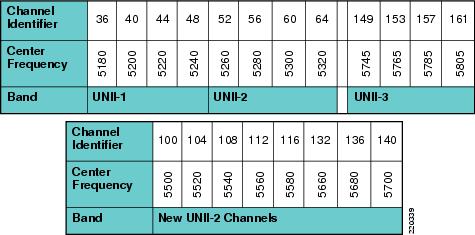
Figure 11-3 shows the FCC 802.11a channel assignments. The DFS requirement includes the four original UNNI-2 channels (52-64) and the new eight channels (100-116 and 132-140). The 5 GHz band now has 20 channels. These are non-overlapping channels, which means that they can all be co-located. 2.4 GHz has only three non-overlapping channels. A design allowing co-located channels in a coverage area aggregates the number calls obtainable in a coverage area.
Figure 11-3 802.11a Channel Allocation
Note
The coverage design based on channels may be done to a single floor, as shown in Figure 11-4. In a multi-floor site, the channels can be separated between floors to reduce the possibility of co-channel interference.
Figure 11-4 Single Floor Channel Design
Figure 11-5 illustrates the vertical channel separation.
Figure 11-5 Vertical Channel Separation
Call Capacity
The number of calls on a WiFi channel is limited by a number of factors. First, the media used by the AP and VoWLAN clients is the RF spectrum. RF spectrum cannot be shielded from interference like shielded twisted-pair CAT 5 cable or fiber. The closest WiFi comes to segmentation is channel separation. This open shared media creates the possibility for high packet loss in 802.11. Most of this packet loss is addressed through retransmission of 802.11 frames, which in turn causes jitter. Figure 11-6 illustrates the packet loss relationship as a mean opinion score (MOS).
Figure 11-6 Effective Packet Loss Graphic
In 802.11a as well as 802.11g, the highest coverage range is achieved by the lowest data rate, which is 6 Mbps. The lowest packet error rate is also at 6 Mbps, for the same given power level. Note that in 802.11b, the lowest data rate is 5.5 Mbps; and in 802.11, the lowest rate is 1 Mbps.
A successful coverage area for voice is an area that maintains a packet error rate of 5 percent or less. The MOS scores are ranked as follows:
•
•
•
Figure 11-6 shows that a packet error rate of 5 percent reduces the MOS to a level of "some users satisfied" quality of speech.
The coverage area edge for a phone is where the coverage area drops to a "very satisfied" MOS. This coverage area edge is referred to as the cell edge in this chapter. A cell edge with a 1 percent packet error rate at survey is needed for voice because of the likelihood of multiple phones clients, data clients, co-channel interference, and other un-accounted for interferers. Cell edge and coverage design are defined in detail in other sections of this chapter.
If 802.11 and 802.11b are not required to support legacy 2.4 GHz WiFi clients, Cisco recommends disabling the rates of 1, 2, 5.5, and 11. If those rates are disabled, one or more 802.11g data rates must be set to "required". The data rate of 6 is generally the recommended data rate to be set to "required", but this depends on the cell size design requirements, which may require using a higher bit rate. If possible, an 802.11g-only network is recommended rather than a 802.11b/g network.
Most data clients and phone clients recognize the data rates advertised by the AP in its beacons and probe response. Therefore, the clients send their management, control, multicast, and broadcast packets at the "required" data rates as advertised by the AP. The clients can send their unicast packets at any of the data rates advertised by the AP. Generally, those unicast packets are sent at a data rate that provides the highest reliable data rate for the link between the AP and client. The AP is capable of sending unicast packets at a data rate that is unique to each client link.
SNR is an important consideration for packet reception. The receiving radio is either the AP radio or the phone radio. The SNR is not likely to be the same at both radios of the link. SNR and multipath interference must be considered at the AP and at the coverage area edge. Path loss can be assumed to be the same at both ends of the link.
Cisco recommends for voice applications that the cell edge be determined by using the actually phone at the desired data rate. The voice packets sent between the AP and the phone in WiFi applications are generally unicast RTP G711 packets with a typical size of 236 bytes. The Real-Time Transport Protocol (RTP) packet is based on UDP and IP protocols, and therefore RTP is connectionless. The signal strength, SNR, data rate, and error rates of the phone call can be seen from the AP statistics, either on the autonomous AP or the Lightweight Access Point Protocol (LWAPP) controller. A sample of a phone client's cell edge dBm values for 11g and 11a are shown in Figure 11-7 and Figure 11-8. The call stream statistics are shown in Figure 11-9. The stream metrics can be viewed on the WCS after the voice metrics are enabled. The path to enable the metrics is Configure > Controller > ipaddress > 802.11bg > Voice Parameters > Enable Voice Metrics.
Figure 11-7 11g Client Statistics
Figure 11-8 11a Client Statistics
Figure 11-9 WLC Call Metrics
A decoded RTP packet is shown in Figure 11-10. The packet is originated at a 7960 phone. The over-the-air QoS marking is changed from the AVVID marking to a user priority of 6 following the 802.11e specification. Call statistics on the Cisco 7920 and 7921 phones can be viewed on the phone or by browsing into the phone using the IP address of the phone. After that cell edge is determined from the testing of the actual phone, those numbers can then be adapted to more automated tools to complete the coverage design for the site.
Figure 11-10 Sample VoWLAN Capture
When there is multipath interference at the location where dBm measurements are being taken, it is quite likely that the reported dBm values will be different from packet to packet. A packet may be as much as 5dB higher or lower than the previous packet. It may take several minutes to get an average of the signal value at that measuring spot.
AP Call Capacity
A key part of the planning process for a VoWLAN deployment is to plan the number of simultaneous voice streams per AP. When planning the voice stream capacity of the AP, consider the following points:
Note
•
•
•
•
Various handsets have different WLAN QoS features and capabilities that impact the features that are enabled in the WLAN deployment, and ultimately determine the per-AP call capacity of the AP. Most VoWLAN handsets provide guidance on the number of calls per AP supported by that phone; this should be considered a best case figure where the handset is able to use its optimal QoS features and has full access to the channel capacity.
The actual number of voice streams a channel supports is highly dependent on a number of issues, including environmental factors and client compliance to WMM and CCX specifications. The CCX specifications that are most beneficial to call quality and channel capacity are shown in the table in Figure 11-11. Simulations indicate that a 5 GHz channel can support 14-18 calls. This means a coverage cell can include 20 APs on different channels, with each channel supporting 14 voice streams. The coverage cell can support 280 calls. The number of voice streams supported on a channel with 11b clients is seven; therefore, the coverage cell with three APs on the three non-overlapping channels supports 21 voice streams.
Figure 11-11 CCX VoWLAN Features
Figure 11-11 shows the following:
•
•
•
•
•
•
Several to the CCX features have more than one benefit.
The amount of buffer memory, CPU speed, and radio quality are key factors of the performance of an AP radio. QoS features prioritize the voice and data traffic in the channel. For a further discussion of QoS, see Chapter 5, "Cisco Unified Wireless QoS."
The 802.11e, WMM, and CCX specifications help balance and prevent the overloading of a cell with voice streams. CAC determines whether there is enough channel capacity to start a call; if not, the phone may scan for another channel. The primary benefit of U-ASPD is the saving of WLAN client power by allowing the transmission of frames from the WLAN client to trigger the forwarding of data frames for a client that has been buffered at the AP for power saving purposes. The Neighbor List option provides the phone a list that includes the channel numbers and channel capacity of neighboring APs. This is done to improve call quality, provide faster roams, and improve battery life.
For a further discussion of U-APSD and CAC, see Chapter 3, "WLAN Radio Frequency Design Considerations."
Cell Edge Design
Guidelines for deploying 802.11b VoWLAN handsets have recommended a design with a minimum power of -67 dBm on the cell boundary (see Figure 11-12). These cells are smaller cells than those used in data WLANs of the past.
The -67 dBm is a general measurement. Achieving a packet error of one percent also requires an SNR value of 25 dB or more. Therefore, when determining the likely channel coverage area for a particular phone type, both signal strength of the phone and the noise must be checked on the AP. See Figure 11-8 and Figure 11-11 for determining these values on the autonomous and LWAPP APs.
The -67 dBm measurement has been used for years for 11b phone clients from many vendors. Tests indicate that this same rule of thumb measurement works well for 11g and 11a phone clients.
Figure 11-12 Cell Edge Measurements
For 5 GHz cells, there is less concern about same channel separation because of the number of channels. There are 20 channels, so a two-channel separation is almost always possible. However, in the 2.4 GHz band, only three channels do not overlay in frequency.
For both 5 GHz and 2.4 GHz, the cell needs to be at the floor location where a packet error rate of 1 percent is maintained at the highest data rate desired for a given channel. In the case of 11b, that data rate is 11 Mbps. Thus, from the center (the AP location) to a point on the floor where the phone signal is seen by the AP, the cell edge is -67 dBm.
802.11g and 802.11a phone clients may be capable of rates up to 54 Mbps. Current chip sets support 54 Mbps, but transmit powers do differ. Cisco highly recommends that all links between phone clients and APs be created with matching transmit powers (see Dynamic Transmit Power Control).
Coverage cells can be created for specific data rates. For a high density deployment or a deployment where a large number of calls are required in a small floor space, 11a is recommended because of the number of channels and the 54 Mbps data rate. The lower data rates in 11a can be disabled, the 24 Mbps data rate can be set to "required", and the rates of 36 to 54 can be left enabled.
After using the model of cell edge set to -67 dBm, determine where the error rate of 1 percent is, and then examine the SNR value.
Create the phone test to find the -67dB edge by doing the following:
•
•
•
•
Carefully examine the data sheets of the particular phone device to determine the transmit powers and data rates supported by the phone device in a particular WiFi band. The data sheets for Cisco Unified Wireless IP Phones can be found on http://www.cisco.com. For phones from other vendors, check the website of the vendor.
The 11a maximum transmit powers vary on different channels and with different AP models. The 11g maximum transmit powers vary by model. Cisco Aironet AP data sheets should be carefully examined to determine which AP model supports which data rates. Figure 11-13 shows an example of the maximum 11a transmit power in dBm by channel.
Figure 11-13 Channel Power Assignment
There is a variance of 6 dB from the maximum transmit powers across the 5 GHz band. This means that when using the maximum allowed transmit power throughout a site that allows all channels, there is not equal cell coverage on all channels. It also means that if dynamic channel selection is used, the cell coverage edge may change based on the channel number. However, dynamic channel selection can be tuned (see Chapter 3, "WLAN Radio Frequency Design Considerations.") The default mode of dynamic channel selection accounts for the difference of maximum transmit powers by channel.
Cell transmit power on all APs should not exceed the maximum or desired transmit power of the phone. If the phones maximum or set transmit power is 13 dBm, Cisco recommends that all APs have a maximum transmit power of 13 dBm. Next, the maximum transmit power on the AP should be set to an equal transmit power or the next higher transmit power. Equal transmit power is recommended to avoid one-way audio. The AP generally has better receiver sensitivity and diversity support than the phone, so it should be able to receive the slightly lower strength phone signal. See Dynamic Transmit Power Control for more information on equal transmit powers.
Dual Band Coverage Cells
Chapter 3, "WLAN Radio Frequency Design Considerations," illustrates 2.4 GHz and 5 GHz band channel coverage design. For a dual mode AP to provide equal cell coverage on both the 2.4 GHz channel and the 5 GHz channel, the 2.4 GHz channel must have an equal (or more likely lower) transmit power than the 5 GHz channel.
At most sites, the noise level in the SNR formula will be lower by perhaps 10 dB. The receiver sensitivity of 11g radios is generally 2 dBm better than the same data rate on the 11a radio. As an example, the data sheet for the 7921 has the receive sensitivity of -78 dBm at the data rate of 36 Mbps for 11g, and -76 dBm for 11a. Therefore, given the anticipated better noise floor of 10 dB, the 11a cell can do better by 8 dBm. Other details such as the difference in path loss between 11g and 11a keep this from being a direct ratio. However, if the same coverage cells are desired, reducing the 11g network by one or two power levels from the 11a network should accomplish this goal.
Dynamic Transmit Power Control
Cisco Aironet APs by default have DTPC enabled. DTPC is automatic with the LWAPP controllers and is configurable on the autonomous APs. Clients need CCX version 2 capabilities to use DTPC. DTPC accomplishes the following:
•
•
•
DTPC allows the phone to automatically adjust its transmit power to that of the APs. In the example shown in Figure 11-14, this means that the phone changes its transmit from 5 mW to 100 mW.
Figure 11-14 Client and AP Power Matching
802.11g and 802.11a clients do not have 100 mW transmit powers. Cisco highly recommends that the maximum configured transmit power on the access be no higher than the client phone devices hardware supports. A phone with a slightly lower transmit power than the AP is better than the AP using less power than the phone. Having matching transmit powers lessens the likelihood of one-way audio (the typical user experience of "can you hear me.... I can't hear you").
Interference Sources Local to the User
Interference can be local to the user, but is also likely to affect nearby users. Bluetooth (BT) is a popular RF protocol used in personal area networks that interferes with WiFi 2.4 GHz channels. Figure 11-15 shows that the actual BT signal does span all the 2.4 GHz channels used by 802.11b/g clients. This graphic is from a 802.11g call with a BT headset attached to the phone. Figure 11-15 also shows the jitter caused by the BT headset.
Figure 11-15 Bluetooth (BT) Signal Pattern in the 802.11b/g 2.4 GHz Spectrum of a Typical BT Earpiece
The PINK is the Max Hold line, or the line that shows the maximum transmit power that was reached during the test. The YELLOW shows the maximum transmit power in the last sample period of ten seconds. The TURQUOISE shows the average transmit power over the period of the test. The vertical dashed lines separate the three non-overlapping 802.11b/g channels Ch1, Ch6, and Ch11. The charting is from 2.400 GHz on the left to 2.500 GHz on the right. From the right edge of the Ch11 vertical blue line is the part of the 802.11 spectrum used in Europe and Japan. This capture was done with an AP and clients configured for the North American regulator domain. This graph shows that the BT earpiece was easily transmitting outside of FCC regulations.
Notice that the BT signal is very narrow. BT transmits data on a single MHz of frequency, stops the transmission, moves to another frequency in the 802.11 2.4 GHz band, and then transmits data. This is repeated continually. The 802.11b and 802.11g signals are sent with a combined 22 MHz of frequency. The radio remains on that 22 MHz of frequency. This grouping of 22 MHz is referred to as the channel. The Max Hold line shows how strong the BT is while in search mode. The signal level is above that of a 50 mW (17 dBm) OFDM 802.11g radio. A signal of this strength and duration causes 802.11b/g phones to drop the VoWLAN call. Lesser strength BT signals cause jitter, resulting in a lower MOS value.
Figure 11-16 shows an example of an Ethereal jitter analysis of three simultaneous phone calls, each using a BT earpiece.
Figure 11-16 Jitter Analysis Example
All three calls were on the same AP, and were calls to other phones on this AP.