Table Of Contents
Wireless QoS Deployment Schemes
QoS Advanced Features for WLAN Infrastructure
Setting the Admission Control Parameters
Impact of TSpec Admission Control
802.11e, 802.1p, and DSCP Mapping
Deploying QoS Features Cisco on LWAPP-based APs
Guidelines for Deploying Wireless QoS
Traffic Shaping, Over the Air QoS and WMM Clients
Cisco Unified Wireless QoS
Introduction
This chapter describes quality of service (QoS) in the context of WLAN implementations. This chapter describes WLAN QoS in general, but does not provide in-depth coverage on topics such as security, segmentation, and voice over WLAN (VoWLAN), although these topics have a QoS component. This chapter also provides information on the features of the Cisco Centralized WLAN Architecture.
This chapter is intended for those who are tasked with designing and implementing enterprise WLAN deployments using the Cisco Unified Wireless technology.
QoS Overview
QoS refers to the capability of a network to provide better service to selected network traffic over various network technologies. QoS technologies provide the following benefits:
•
Provides building blocks for business multimedia and voice applications used in campus, WAN, and service provider networks
•
•
•
With QoS, bandwidth can be managed more efficiently across LANs, including WLANs and WANs. QoS provides enhanced and reliable network service by:
•
•
•
•
•
Wireless QoS Deployment Schemes
In the past, WLANs were mainly used to transport low-bandwidth, data-application traffic. Currently, with the expansion of WLANs into vertical (such as retail, finance, and education) and enterprise environments, WLANs are used to transport high-bandwidth data applications, in conjunction with time-sensitive, multimedia applications. This requirement led to the necessity for wireless QoS.
Several vendors, including Cisco, support proprietary wireless QoS schemes for voice applications. To speed up the rate of QoS adoption and to support multi-vendor time-sensitive applications, a unified approach to wireless QoS is necessary. The IEEE 802.11e working group within the IEEE 802.11 standards committee has completed the standard definition, but adoption of the 802.11e standard is in its early stages, and as with many standards there are many optional components. Just as occurred with 802.11 security in 802.11i, industry groups such as the WiFi Alliance and industry leaders such as Cisco are defining the key requirements in WLAN QoS through their WMM and CCX programs, ensuring the delivery of key features and interoperation through their certification programs.
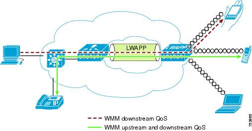
Cisco Unified Wireless Products support Wi-Fi MultiMedia (WMM), a QoS system based on the IEEE 802.11e draft that has been published by the Wi-Fi Alliance. An example deployment of wireless QoS based on Cisco Unified Wireless technology features is shown in Figure 5-1.
Figure 5-1 Wireless QoS Deployment Example
QoS Parameters
QoS is defined as the measure of performance for a transmission system that reflects its transmission quality and service availability. Service availability is a crucial element of QoS. Before QoS can be successfully implemented, the network infrastructure must be highly available. The network transmission quality is determined by latency, jitter, and loss, as shown in Table 5-1.
Upstream and Downstream QoS
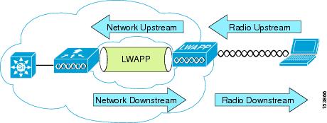
Figure 5-2 illustrates the definition of QoS radio upstream and downstream.
The notations in Figure 5-2 refer to the following:
•
•
•
•
Figure 5-2 Upstream and Downstream QoS
QoS and Network Performance
The application of QoS features might not be easily detected on a lightly loaded network. If latency, jitter, and loss are noticeable when the media is lightly loaded, it indicates a system fault, poor network design, or that the latency, jitter, and loss requirements of the application are not a good match for the network.
QoS features start to impact application performance as the load on the network increases. QoS works to keep latency, jitter, and loss for selected traffic types within acceptable boundaries.
When providing only radio downstream QoS from the AP, radio upstream client traffic is treated as best-effort. A client must compete with other clients for upstream transmission as well as competing with best-effort transmission from the AP. Under certain load conditions, a client can experience upstream congestion and the performance of QoS-sensitive applications might be unacceptable despite the QoS features on the AP.
Ideally upstream and downstream QoS can be operated either by using WMM on both the AP and WLAN client, or by using WMM and a client's proprietary implementation.
Note
Note
802.11 DCF
Data frames in 802.11 are sent using the Distributed Coordination Function (DCF), which is composed of two main components:
•
•
DCF is used in 802.11 networks to manage access to the RF medium. A baseline understanding of DCF is necessary to deploy 802.11e-based enhanced distributed channel access (EDCA). See the IEEE 802.11 specification for more information on DCF at the following URL: http://ieeexplore.ieee.org/xpl/standardstoc.jsp?isnumber=14251&isYear=1997
Interframe Spaces
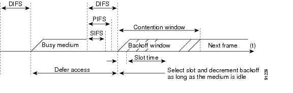
802.11 currently defines three interframe spaces, as shown in Figure 5-3:
•
•
•
The interframe spaces, SIFS, PIFS, and DIFS allow 802.11 to control which traffic gets first access to the channel after carrier sense declares the channel to be free.
Figure 5-3 Interframe Spaces (IFS)
Random Backoff
When a data frame using Distributed Coordination Function (DCF), shown in Figure 5-4, is ready to be sent, it goes through the following steps:
1.
2.
3.
4.
5.
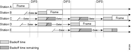
Figure 5-4 shows a simplified example of how the DCF process works. In this simplified DCF process, no acknowledgements are shown and no fragmentation occurs.
Figure 5-4 Distributed Coordination Function Example
The DCF steps illustrated in Figure 5-4 are as follows:
1.
2.
3.
4.
5.
6.
7.
CWmin, CWmax, and Retries
DCF uses a contention window (CW) to control the size of the random backoff. The contention window is defined by two parameters:
•
•
The random number used in the random backoff is initially a number between 0 and aCWmin. If the initial random backoff expires without successfully sending the frame, the station or AP increments the retry counter, and doubles the value random backoff window size. This doubling in size continues until the size equals aCWmax. The retries continue until the maximum retries or time to live (TTL) is reached. This process of doubling the backoff window is often referred to as a binary exponential backoff, and is illustrated in Figure 5-5.
Figure 5-5 Growth in Random Backoff Range with Retries
Wi-Fi Multimedia
This section describes three Wi-Fi Multimedia (WMM) implementations:
•
•
•
WMM Access
WMM is a Wi-Fi Alliance certification of support for a set of features from the 802.11e draft. This certification is for both clients and APs, and certifies the operation of WMM. WMM is primarily the implementation of the EDCA component of 802.11e. Additional Wi-Fi certifications are planned to address other components of the 802.11e.
Figure 5-6 shows the principle behind EDCF, where different interframe spacing and CWmin and CwMax values are applied per traffic classification. Different traffic types can wait different interface spaces before counting down their random backoff, and the CW value used to generate the random backoff number also depends on the traffic classification. High priority traffic has small interframe space and a small CWmin value, giving as short random backoff, whereas best-effort traffic has a longer interframe space and large CWmin value that on average gives a large random backoff number.
Figure 5-6 Access Category Timing
WMM Classification
WMM uses the 802.1p classification scheme developed by the IEEE (which is now a part of the 802.1D specification).
This classification scheme has eight priorities, which WMM maps to four access categories: AC_BK, AC_BE, AC_VI, and AC_VO. These access categories map to the four queues required by a WMM device, as shown in Table 5-2.
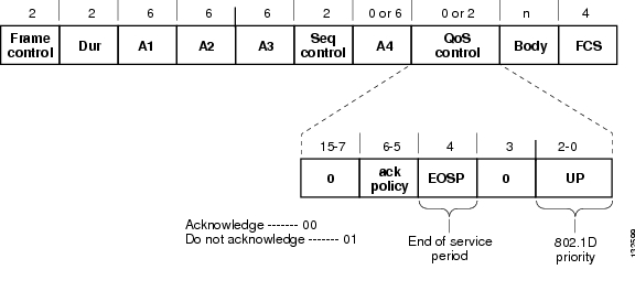
Figure 5-7 shows the WMM data frame format. Note that even though WMM maps the eight 802.1p classifications to four access categories, the 802.11D classification is sent in the frame.
Note
Figure 5-7 WMM Frame Format
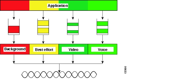
WMM Queues
Figure 5-8 shows the queuing performed on a WMM client or AP. There are four separate queues, one for each of the access categories. Each of these queues contends for the wireless channel in a similar manner to the DCF mechanism described previously, with each of the queues using different interframe space, CWmin, and CWmax values. If more than one frame from different access categories collide internally, the frame with the higher priority is sent, and the lower priority frame adjusts its backoff parameters as though it had collided with a frame external to the queuing mechanism. This system is called enhanced distributed channel access (EDCA).
Figure 5-8 WMM Queues
EDCA
The EDCA process is illustrated in Figure 5-9, using data from Figure 5-10, and follows this sequence:
1.
2.
3.
4.
5.
6.
7.
Note
Figure 5-9 EDCA Example
The overall impact of the different AIFS, CWmin, and CWmax values is difficult to illustrate in timing diagrams because their impact is more statistical in nature. It is easier to compare the AIFS and the size of the random backoff windows, as shown in Figure 5-10.
Figure 5-10 AIFS and CWmin for Different Access Categories
When comparing voice and background frames as examples, these traffic categories have CWmin values of 3 (7) and 5 (31), and AIFS of 2 and 7, respectively. This an average delay of 5 slot times before sending a voice frame, and an average of 22 slot times for background frame. Therefore, voice frames are statistically much more likely to be sent before background frames.
U-APSD
Unscheduled automatic power-save delivery (U-APSD) is a feature that has two key benefits:
•
The client remains listening to the AP until it receives a frame from the AP with an end of service period (EOSP) bit set. This tells the client that it can now go back into its power save mode. This triggering mechanism is considered a more efficient use of client power than the regular listening for beacons method, at a period controlled by the delivery traffic indication message (DTIM) interval, as the latency and jitter requirements of voice are such that a WVoIP client would either not save power during a call, resulting in reduced talk times, or use a short DTIM interval, resulting in reduced standby times. The use of U-APSD allows the use of long DTIM intervals to maximize standby time without sacrificing call quality. The U-APSD feature can be applied across access categories; U-APSD can be applied to the voice ACs in the AP, but the other ACs can still use the standard power save feature.
•
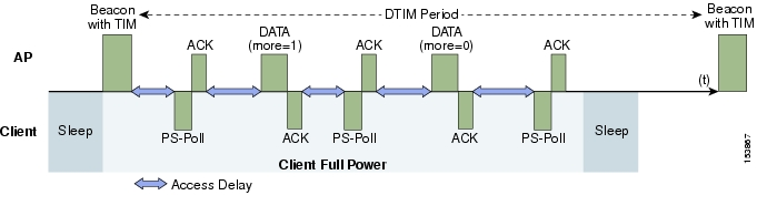
Figure 5-11 shows an example frame exchange for the standard 802.11 power save delivery process. The client in power save mode first detects that there is data waiting for it at the AP via the presence of the TIM in the AP beacon. The client must power-save poll (PS-Poll) the AP to retrieve that data. If the data sent to the client requires more than one frame to be sent, the AP indicates this in the sent data frame. This process requires the client to continue sending power save polls to the AP until all the buffered data is retrieved by the client.
This presents two major problems. The first is that it is quite inefficient, requiring the PS-polls, as well as the normal data exchange, to go through the standard access delays associated with DCF. The second issue, being more critical to voice traffic, is that retrieving the buffered data is dependent on the DTIM, which is a multiple of the beacon interval. Standard beacon intervals are 100mS and the DTIM interval can be integer multiples of this. This introduces a level of jitter that is generally unacceptable for voice calls, and voice handsets switch from power save mode to full transmit and receive operation when a voice call is in progress. This gives acceptable voice quality but reduces battery life.
Figure 5-11 Standard Client Power Save
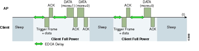
Figure 5-12 shows an example of traffic flows with U-APSD. In this case, the trigger for retrieving traffic is the client sending traffic to the AP. The AP, when acknowledging the frame, tells the client that data is queued for it, and that is should stay on. The AP then sends data to the client typically as a TXOP burst where only the first frame has the EDCF access delay. All subsequent frames are then sent directly after the acknowledgment frame.
This approach overcomes both of the disadvantages of the previous scheme in that it is much more efficient. The timing of the polling is controlled via the client traffic, which in the case of voice is symmetric, so if the client is sending a frame every 20mSec, it would be expecting to receive a frame every 20mSec as well. This would introduce a maximum jitter of 20mSec, rather than an n * 100mSec jitter.
Figure 5-12 U-APSD
TSpec Admission Control
Traffic Specification (TSpec) allows an 802.11e client to signal to the AP its traffic requirements. In the 802.11e MAC definition, there are two mechanisms to provide prioritized access. These are the contention-based EDCA option and the controlled access option provided by the transmit opportunity (TXOP).
When describing TSpec features where a client can specify its traffic characteristics, it is easy to assume that this would automatically result in the use of the controlled access mechanism, and have the client granted a specific TXOP to match the TSpec request.
This does not have to be the case; a TSpec request can be used to control the use of the various access categories (ACs) in EDCA. Before a client can send traffic of a certain priority type, it must have requested to do so via the TSpec mechanism. For example, a WLAN client device wanting to use the voice AC must first make a request for use of that AC. Whether AC use is controlled by TSpec requests or is openly configurable can be controlled by TSpec requests, but best-effort and background ACs can be open for use without a TSpec request.
The use of EDCA ACs, rather than the HCCA, to meet TSpec requests is possible in many cases because the traffic parameters are sufficiently simple to allow them to be met by allocating capacity, rather than creating a specific TXOP to meet the application requirements.
The TSpec admission control to an AC acts in a manner similar to Cisco CallManager in that it knows how much capacity is available at a branch (AP), and does not allow additional calls when that capacity is consumed. This is done without the CallManager having to specifically allocate resources in the path of the VoIP call.
Note
Add Traffic Stream
The Add Traffic Stream (ADDTS) function is how a WLAN client performs an admission request to an AP. Signalling its TSpec to the AP.
An admission request is in one of two forms:
•
•
The ADDTS contains the TSpec element that describes the traffic request (see Table 5-5). Apart from key data describing the traffic requirements, such as data rates and frame sizes, the TSpec element also tells the AP the minimum physical rate that the client device will use. This allows the calculation of how much time that station can potentially consume in sending and receiving in this TSpec, and therefore allowing the AP to calculate whether it has the resources to meet the TSpec.
TSpec admission control is used by the WLAN client (target clients are VoIP handsets) when a call is initiated and during a roam request. During a roam, the TSpec request is appended to the re-association request.
Sample TSpec Decode
Vendor Specific: WME Tag Number: 221 (Vendor Specific)Tag length: 61Tag interpretation: WME TSPEC: type 2, subtype 2, version 1Tag interpretation: WME TS Info: Priority 4 (Controlled Load) (Video), Contention-based access set, Bi-directionalTag interpretation: WME TSPEC: Fixed MSDU Size 5632Tag interpretation: WME TSPEC: Maximum MSDU Size 56448Tag interpretation: WME TSPEC: Minimum Service Interval 5Tag interpretation: WME TSPEC: Maximum Service Interval 0Tag interpretation: WME TSPEC: Inactivity Interval 0Tag interpretation: WME TSPEC: Service Start Time 4294967040Tag interpretation: WME TSPEC: Minimum Data Rate 255Tag interpretation: WME TSPEC: Mean Data Rate 40960Tag interpretation: WME TSPEC: Maximum Burst Size 40960Tag interpretation: WME TSPEC: Minimum PHY Rate 40960Tag interpretation: WME TSPEC: Peak Data Rate 0Tag interpretation: WME TSPEC: Delay Bound 0Tag interpretation: WME TSPEC: Medium Time 23437QoS Advanced Features for WLAN Infrastructure
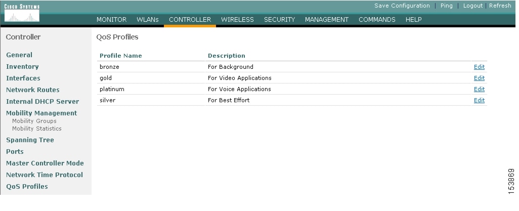
Cisco Centralized WLAN Architecture has multiple QoS features, in addition to WMM support. Primary among these is the QoS profiles in the WLC. Four QoS profiles can be configured: platinum, gold, silver, and bronze, as shown in Figure 5-13.
Figure 5-13 WLC QoS Profiles
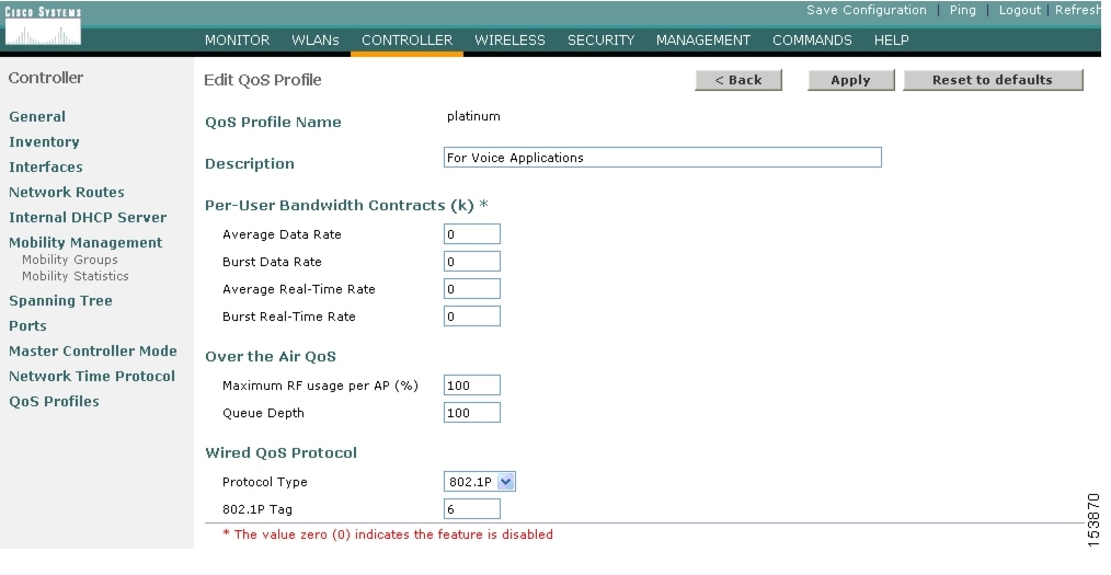
Each of these profiles (see Figure 5-14) allows the configuration of bandwidth contracts, RF usage control, and the maximum 802.1p classification allowed. It is generally recommended that these settings be left at their default values, and that the 802.11 WMM features be used to provide differentiated services.
Figure 5-14 QoS Profile Options
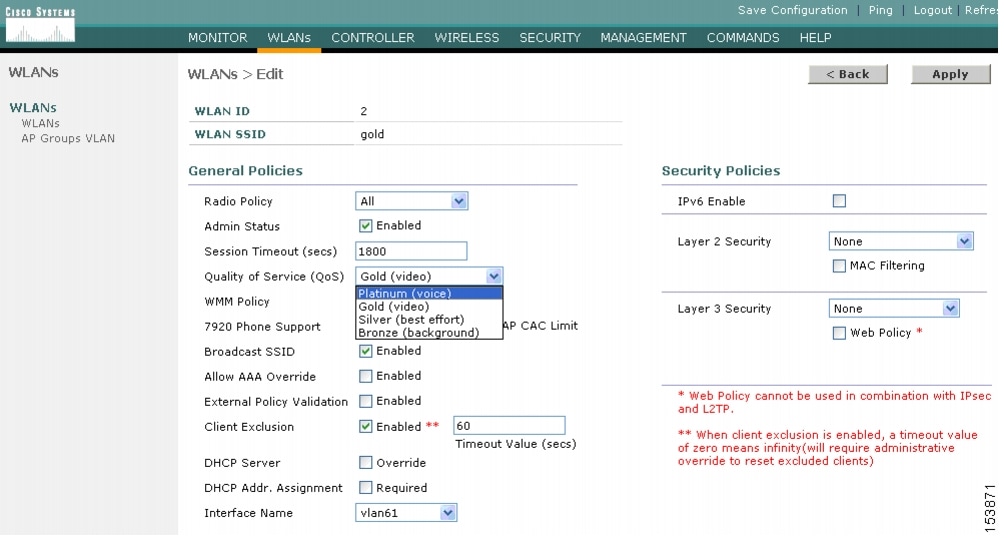
The WLAN can be configured with different default QoS profiles, as shown in Figure 5-15. Each of the profiles (platinum, gold, silver, and bronze) are annotated with their typical use. In addition, clients can be assigned a QoS profile based on their identity, through AAA.
For a typical enterprise, WLAN deployment parameters, such as per-user bandwidth contracts and over the air QoS should be left at their default values, and standard QoS tools, such as WMM and wired QoS, should be used to provide optimum QoS to clients.
Figure 5-15 WLAN QoS Profile Settings
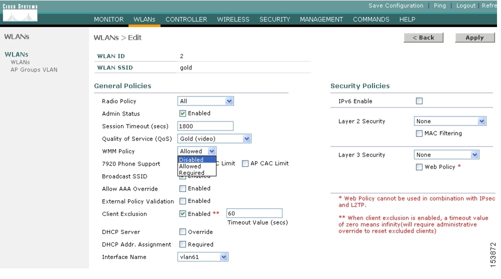
In addition to the QoS profiles, the WMM policy per WLAN can also be controlled, as shown in Figure 5-16. The three WMM options are disabled, allowed, or required. Disabled means that the WLAN does not advertise WMM capabilities, or allow WMM negotiations, Allowed means that the WLAN does allow WMM and non-WMM clients, and required means that only WMM-enabled clients can be associated with this WLAN.
Figure 5-16 WLAN WMM Policy
IP Phones
Figure 5-17 shows the basic QBSS information element (IE) advertised by a Cisco AP. The Load field indicates the portion of available bandwidth currently used to transport data on that AP.
Figure 5-17 QBSS Information Element
There are actually three QBSS IEs that need to be supported in certain situations:
•
•
•
This QBSS depends on the WMM and 7920 settings on the WLAN.
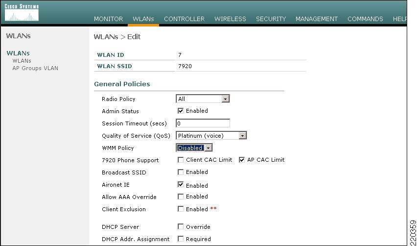
7920 phone support, shown in Figure 5-18, is a component of the WLC WLAN configuration that enables the AP to include the appropriate QBSS element in its beacons. WLAN clients with QoS requirements use these advertised QoS parameters to determine the best AP with which to associate.
Figure 5-18 7920 Phone Support
The WLC provides 7920 support through the client CAC limit, or AP CAC limit. These features provide the following:
•
•
The various combinations of WMM, client CAC limit, and AP CAC limit result in different QBSS IEs being sent:
•
•
•
Note
Setting the Admission Control Parameters
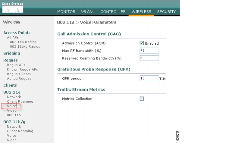
Figure 5-19 shows an example configuration screen for setting the voice parameters on the controller. The admission control parameters consist of the maximum RF capacity that a radio can have and still accept the initiation of a VoIP call through a normal ADDTS request. The reserved roaming bandwidth is how much capacity has been set aside to be able to respond to ADDTS requests during association or re-association, which are WVoIP clients with calls in progress that are trying to roam to that AP.
When checked, the Gratuitous Probe Response checkbox causes APs to send a probe response at a regular interval (default 10mSec) to assist certain WVoIP phones in making roaming decisions. The use of the probe response is considered more efficient and less disruptive than increasing the beacon rate of APs.
The Traffic Stream Metrics Collection option determines if data is collected on voice or video calls for use by the WCS.
Note
Figure 5-19 Configuring Voice Parameters
Impact of TSpec Admission Control
The purpose of TSpec admission control is not to deny clients access to the WLAN; it is to protect the high priority resources. Therefore, a client that has not used TSpec admission control does not have its traffic blocked; it simply has its traffic re-classified if it tries to send (which it should not do if the client is transmitting WMM compliant-traffic in a protected AC).
Table 5-6 and Table 5-7 describe the impact on classification if Access Control is enabled and dependent on whether a traffic stream has been established.
802.11e, 802.1p, and DSCP Mapping
WLAN data in a centralized WLAN deployment is tunneled via LWAPP. To maintain the QoS classification that has been applied to data traffic, a process transferring or applying classification is required.
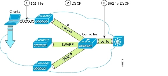
For example, when WMM classified traffic is sent by a WLAN client, it has an 802.1p classification in its frame. The AP needs to translate this classification into a DSCP value for the LWAPP packet carrying the frame to ensure that the packet is treated with the appropriate priority on its way to the WLC. A similar process needs to occur on the WLC for LWAPP packets going to the AP.
A mechanism to classify traffic from non-WMM clients is also required, so that their LWAPP packets can also be given an appropriate DSCP classification by the AP and the WLC.
Figure 5-20 shows the various classification mechanisms in the LWAPP WLAN network. The multiple classification mechanisms and client capabilities require multiple strategies:
•
•
•
•
Figure 5-20 WMM, DSCP, and 802.1p Relationship
AVVID Priority Mapping
The LWAPP AP and WLC perform AVVID conversion, so that WMM values as shown in Table 5-8 are mapped to the appropriate AVVID DSCP values, rather than the IEEE values.
Deploying QoS Features Cisco on LWAPP-based APs
When deploying WLAN QoS on the APs, consider the following:
•
•
•
•
•
QoS and the H-REAP
For WLANs that have data traffic forwarded to the WLC, behavior is same as non H-REAP APs.
For locally switched WLANs with WMM traffic, the AP marks the dot1p value in the dot1q VLAN tag for upstream traffic. This occurs only on tagged VLANs; that is, not native VLANs. For downstream traffic for locally switched WLANs, the H-REAP uses the incoming dot1q tag from the Ethernet side and marks the WMM values on the wireless side. The WLAN QoS profile is applied both for upstream and downstream packets; that is, for downstream if an 802.1p value that is higher than the default WLAN value is received, the default WLAN value is used. For upstream, if the client sends an WMM value that is higher than the default WLAN value, the default WLAN value is used.
For non-WMM traffic, there is no CoS marking on the client frames from the AP.
Guidelines for Deploying Wireless QoS
The same rules for deploying QoS in a wired network apply to deploying QoS in a wireless network. The first and most important guideline in QoS deployment is to know your traffic. Know your protocols, your application's sensitivity to delay, and traffic bandwidth. QoS does not create additional bandwidth, it simply gives more control of where the bandwidth is allocated.
Throughput
An important consideration when deploying 802.11 QoS is to understand the offered traffic, not only in terms of bit rate, but also in terms of frame size, because 802.11 throughput is sensitive to the frame size of the offered traffic.
Table 5-9 shows the impact that frame size has on throughput: as packet size decreases, so does throughput. For example, if an application offering traffic at a rate of 3Mbps is deployed on an 11Mbps 802.11b network, but uses an average frame size of 300 bytes, no QoS setting on the AP allows the application to achieve its throughput requirements. This is because 802.11b cannot support the required throughput for that throughput and frame size combination. The same amount of offered traffic, having a frame size of 1500 bytes, does not have this issue.
Table 5-9 Throughput Compared to Frame Size
11g - 54Mbps
11.4
19.2
24.6
28.4
31.4
Throughput bps
11b - 11Mbps
2.2
3.6
4.7
5.4
6
Throughput bps
Traffic Shaping, Over the Air QoS and WMM Clients
Traffic shaping and over the air QoS are useful tools in the absence of WLAN WMM features, but they do not address the prioritization of 802.11 traffic directly. For WLANs that support WMM clients or 7920 handsets, the WLAN QoS mechanisms of these clients should be relied on; no traffic shaping or over the air QoS should be applied to these WLANs.
WLAN Voice and the Cisco 7920
The Cisco 7920 is a Cisco 802.11b VoIP handset, and its use is one of the most common reasons for deploying QoS on a WLAN.
Deploying voice over WLAN infrastructure involves more than simply providing QoS on WLAN. A voice WLAN needs to consider site survey coverage requirements, user behavior, roaming requirements and admission control. This is covered in the Cisco Wireless IP Phone 7920 Design and Deployment Guide, at the following URL: http://www.cisco.com/en/US/docs/voice_ip_comm/cuipph/7920/5_0/english/design/guide/7920ddg.html.