Table Of Contents
Cisco Unified Wireless Security Integration
Appliance and Module Integration
Cisco Integrated Security Features Integration
ARP Spoofing-based Man-In-the-Middle Attack
Using Port Security to Mitigate a MAC Flooding Attack
Port Security in a Wireless Network
Effectiveness of Port Security
Using Port Security to Mitigate a DHCP Starvation Attack
Using DHCP Snooping to Mitigate a Rogue DHCP Server Attack
Using Dynamic ARP Inspection to Mitigate a Man-in-the-Middle Attack
Using IP Source Guard to Mitigate IP and MAC Spoofing
Cisco Unified Wireless Security Integration
This chapter discusses the integration of wired network security into the Cisco Unified Wireless Solution.
Cisco provides a wide range of security features and products that are applicable to the Cisco Unified Wireless Solution. This chapter provides a collection of best practices that help integrate the most common security features and products into a wireless environment. The three areas of discussion are the following:
•
Intrusion detection systems (IDS) and intrusion protection systems (IPS) integration
•
•
Note
IDS and IPS Integration
An IDS operates by first detecting an attack occurring at the network level, and then by either triggering a corrective action or notifying a management system so that an administrator can take action.
An IPS performs a similar analysis to that of an IDS, but is inline with the traffic flow. Rather than simply notifying network nodes about security issues, an IPS can block traffic that matches attack signatures. This gives the IPS the ability to block an attack on the fly rather than simply detecting it.
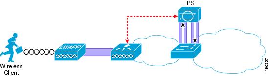
Figure 9-1 illustrates the IPS concept of the IPS being inserted into the data path, and signaling the Wireless LAN Controller (WLC) when an attack is blocked.
Figure 9-1 IPS Inline with Traffic
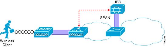
Figure 9-2 illustrates the IDS concept of the IDS analyzing; in this case, by receiving a copy of that data through a SPAN port, and signaling the WLC about an attack that should be blocked.
Figure 9-2 IDS Monitoring Traffic
Both IDS and IPS have their place in the network. It is not the goal of this chapter to discuss the merits of either, but rather to show how a Cisco IDS or IPS can integrate with the Cisco Unified Wireless Solution to block access to the network by detected attackers.
Note
Overview
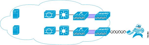
The location of the IPS system in the network depends on the chosen security architecture; the IPS can be directly inline with the WLC, or may be in another network location, to provide protection for specific network resources. Figure 9-3 shows a schematic of the IPS deployed to protect specific network resources by analyzing all traffic to that resource. For example, the IPS may be deployed to analyze traffic to certain mission-critical servers.
Figure 9-3 Data Center IDS
Figure 9-4 shows the IPS deployed to provide general protection of network resources by analyzing all WLAN client traffic from the WLC, ensuring that all traffic from the WLAN client is analyzed.
The chosen IDS deployment option chosen depends on the intended resource to be protected, the capacity of the IDS system, and the architecture of the WLAN system. The data center deployment has the advantage of requiring IDS hardware to be deployed only where the protected asset is located in the network, but does not protect against all possible WLAN exploits. The IPS-at-the-WLC deployment has the advantage of protecting against all WLAN-originated exploits, regardless of target.
Figure 9-4 IDS at the WLC
Operation
For the WLC to be able to disconnect a client attack detected by the IPS, it must learn about the client. To do this, the WLC regularly polls the IPS for information on which clients are currently targets for shunning. The IPS returns the IP addresses of currently shunned clients; the WLC uses this information to disconnect clients with those IP addresses in the WLC mobility group.
The minimum polling time is ten seconds, which means that there is a potential delay between the time that the attack is detected and the time the attacker is blocked at the WLC.
Although this means that there may be a delay in disconnecting the detected client because of the polling interval, it removes any requirement for the IPS to be aware of the network topology, and to send shun information to a specific WLC. The delay introduced by polling needs to be viewed in context of the overall IPS system, where the IPS itself has taken action to block an attack and shuns the client, and the WLC acting to augment functionality by disconnecting the offending client from the network.
Note
WLC Configuration
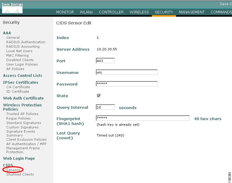
Figure 9-5 shows the WLC configuration page for connection to an IPS. The WLC establishes the connection to the IPS, normally through port 443. A viewing account must exist on the IPS to which the WLC can connect through its username and password. A Transport Layer Security (TLS) certificate hash of the IPS server is also required.
The state check box controls whether the WLC attempts to connect with the IPS. If the box is checked and the configuration is correct, the connection is active; if the box is unchecked, the connection is inactive.
Figure 9-5 WLC IPS Sensor Configuration
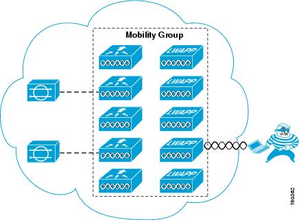
Mobility Considerations
The IPS client shun information is distributed throughout the WLC mobility group by the controller connected to the IPS. To use the information generated by an IPS, only one WLC of the mobility group needs to be a client of that IPS; all other WLCs in the mobility group receive the IPS from the connected WLC. Figure 9-6 shows a schematic of the connection between the WLC mobility group and the IPS(s). The WLC mobility group can be connected to one or more IPS(s) by any WLC member of the mobility group, and the IPS information is then distributed throughout the mobility group.
Figure 9-6 Mobility Group IDS Connection
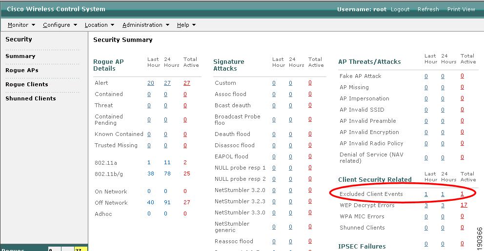
Client Shun Example
This section provides an example of a client shun on the WLC, and how it is displayed and reported.
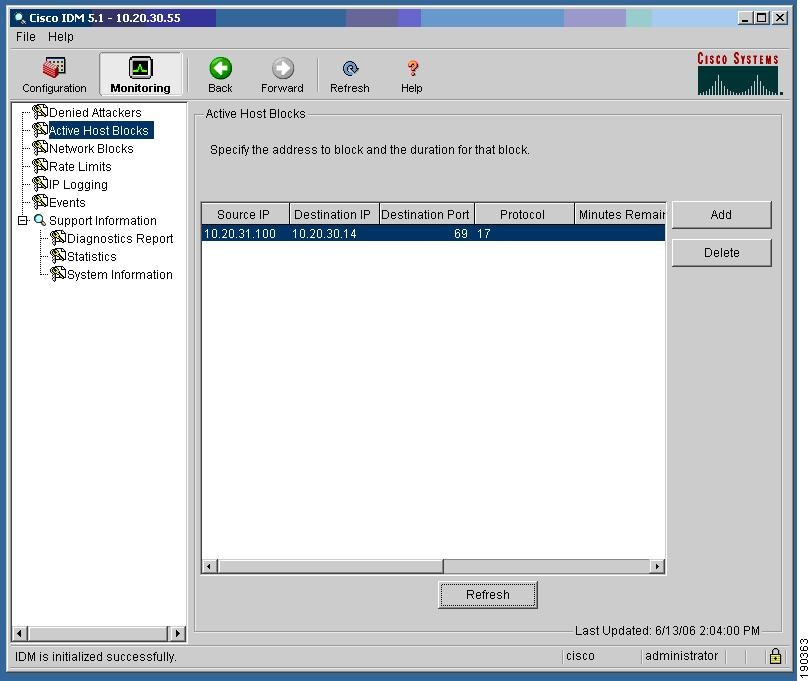
Figure 9-7 shows the IPS report of a blocked host on the IPS.
Figure 9-7 Client Blocked at IPS
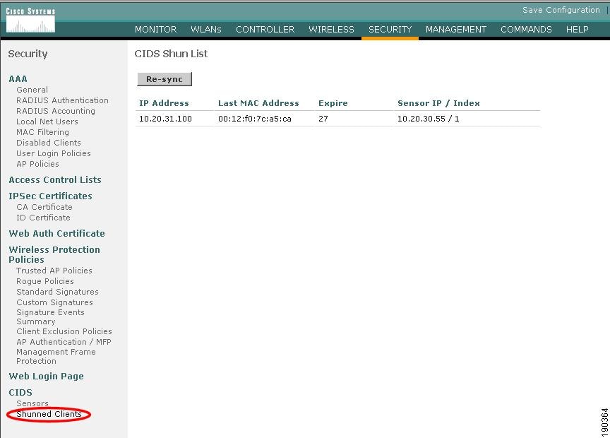
Figure 9-8 shows the shunned client report on a WLC that appears after a subsequent poll of the IPS.
Figure 9-8 Client Shun on WLC
Note that the list is based on IP address. AWLC must learn the client IP address before it can learn which client MAC address to shun. Therefore, the shunning of clients based on IPS lists does not occur until the WLAN client has associated and authenticated with the WLAN. As long as the client is in the shun list on the WLCs, it is excluded; therefore, excluded clients need to be cleared from the IPS before they can cease being excluded by WLCs.
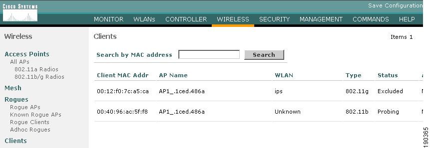
If the shunned WLAN client exists on the WLC, it is excluded, as shown in Figure 9-9.
Figure 9-9 Client Excluded
The excluding of the WLAN client is recorded on the WCS as an alarm, as shown in Figure 9-10 and Figure 9-11.
Figure 9-10 WCS Record
Figure 9-11 WCS Alarm Detail
Appliance and Module Integration
Cisco provides a wide variety of security features that are either integrated into Cisco IOS, integrated into modules, or offered as appliances. The Cisco Unified Wireless architecture eases the integration of these security features into the solution because it provides a Layer 2 connection between the WLAN clients and the extended network. This means that appliances or modules that operate by being "inline" with client traffic can be easily inserted between the WLAN clients and the core network. For example, a Cisco Wireless LAN Services Module (WLSM) implementation requires the implementation of VRF-Lite on the Cisco 6500 to ensure that the WLAN client traffic flows through a Cisco Firewall Service Module (FWSM), whereas a Cisco Wireless Services Module (WiSM) implementation can simply map the WLAN client VLAN directly to the FWSM.
The only WLAN controller not able to directly map the Layer 2 WLAN client traffic to a physical interface is the WLC ISR module (NM-AIR-WLC6). The ISR module does have access to all the IOS and IPS features available on the ISR, and the IP traffic from the WLAN clients can be forced in and out specific ISR interfaces using IOS VRF features on the router.
This section discusses the following products:
•
•
•
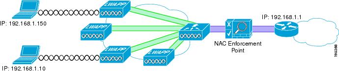
CCAS
The CCAS can sit between the client devices and their default gateway. This is easily achieved with the Cisco Unified Wireless Solution because the WLC provides a Layer 2 connection between the WLAN clients and the CCAS Network Admission Control (NAC) enforcement point, as shown in Figure 9-12.
Figure 9-12 Clean Access Enforcement Point
The WLAN(s) requiring NAC enforcement can be directly mapped via their VLAN to the CCAS, or these WLAN can be mapped via mobility anchors.
The schematic of Figure 9-12 is equally applicable for the integration of other security appliances into the WLAN solution where the selected WLANs are terminated directly to the untrusted interface of a security appliance.
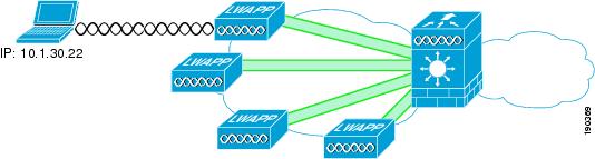
Firewall and VPN Modules
Figure 9-13 shows the WiSM-based solution integrated with the FWSM. This allows the direct connection of selected WLANs to the FWSM.
Figure 9-13 FWSM Integration with WiSM
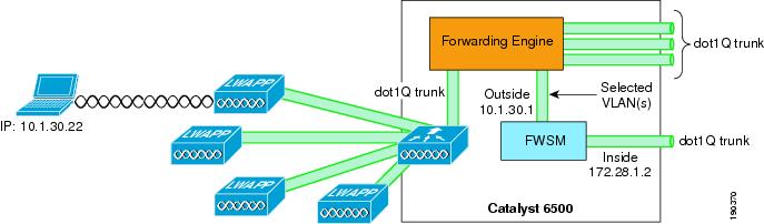
Figure 9-14 shows the logical view of the WiSM FWSM integration, where the WLAN(s) interfaces are connected to the Cisco 6500 forwarding engine through the dot1q trunk configured on the WiSM port channel interface. These WLAN interface VLANs may terminate on the 6500 routing engine or the FWSM module, or be made available outside the 6500. The FWSM interface in this case acts as the default gateway for all traffic from the selected WLAN VLANs.
Figure 9-14 FWSM Logical View
For more information on the FWSM, see the following URL: http://www.cisco.com/en/US/products/hw/modules/ps2706/ps4452/tsd_products_support_model_home.html.
IDSM
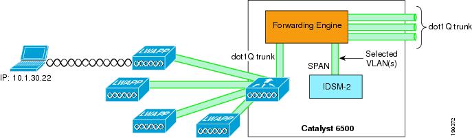
Figure 9-15 shows the WiSM-based solution integrated with the IDSM-2. This allows the direct connection of selected WLANs to the IDSM module through the 6500 backplane.
Figure 9-15 IDSM-2 Module
Figure 9-16 shows the logical view of the WiSM IDSM-2 integration, where the WLAN(s) interfaces are connected to the 6500 forwarding engine through the dot1q trunk configured on the WiSM port channel interface.
Figure 9-16 IDSM-2 Logical View
These WLAN interfaces VLANs may terminate on the 6500 routing engine or be made available outside the 6500, and can also be "spanned" to the IDSM-2. The IDSM-2 is in a passive mode, monitoring traffic to and from the selected WLAN interfaces.
The IDSM-2 may also be connected inline with the WLAN traffic in a similar manner to the FWSM if the module is being implemented for IPS purposes.
For more information on the IDSM-2, see the following URL: http://www.cisco.com/en/US/products/hw/modules/ps2706/products_data_sheet09186a00801e55dd.html
Cisco Integrated Security Features Integration
Cisco Integrated Security Features (CISF), are available on Cisco Catalyst switches, and help mitigate against a variety of attacks that a malicious user might launch after gaining wireless access to the network. This section describes these attacks, how a WLC protects against these attacks, and how CISF, when enabled on the access switch, can help protect the network. It includes the following topics:
•
•
•
•
•
•
Note
Overview
Attacks can occur against either wired or wireless networks. However, a wireless network connection allows an attacker to craft an attack without physical access to the network. The WLC and CISF include features that are specifically designed to prevent attacks, including the following:
•
•
•
–
–
MAC Flooding Attack
MAC flooding attacks are attempts to fill a switch Content-Addressable Memory (CAM) table and force the switch to start flooding LAN traffic. These attacks are performed with tools such as macof (part of the dsniff package), which generates a flood of frames with random MAC and IP source and destination addresses.
The Layer 2 learning mechanism of an Ethernet switch is based on the source MAC addresses of packets. For each new source MAC address received on a port, the switch creates a CAM table entry for that port for the VLAN to which the port belongs. The macof utility typically fills the CAM table in less than ten seconds, given the finite memory available to store these entries on the switch. CAM tables are limited in size. If enough entries are entered into the CAM table before other entries expire, the CAM table fills up to the point that no new entries can be accepted.
A network intruder can flood the switch with a large number of bogus-source MAC addresses until the CAM table fills up. The switch then floods all its ports with incoming traffic because it cannot find the port number for a particular MAC address in the CAM table. The switch, in essence, acts like a hub to the detriment of performance and security. The overflow floods traffic within the local VLAN, so the intruder sees traffic within the VLAN to which he or she is connected.
At Layer 3, the random IP destinations targeted by macof also use the multicast address space. Thus, the distribution layer switches that have multicast turned on experience high CPU usage levels as the protocol independent multicast (PIM) process attempts to handle the false routes.
DHCP Rogue Server Attack
The DHCP rogue server event may be the result of an attack, or a user may accidentally bring up a DHCP server on a network segment and begin inadvertently issuing IP addresses. An intruder may bring up a DHCP server to issue an address with DNS server or default gateway information that redirects traffic to a computer under the control of the intruder.
DHCP Starvation Attack
DHCP starvation attacks are designed to deplete all of the addresses within the DHCP scope on a particular segment. Subsequently, a legitimate user is denied when requesting a DHCP IP address and thus is not able to access the network. Gobbler is a public domain hacking tool that performs automated DHCP starvation attacks. DHCP starvation may be purely a DoS mechanism or may be used in conjunction with a malicious rogue server attack to redirect traffic to a malicious computer ready to intercept traffic.
ARP Spoofing-based Man-In-the-Middle Attack
A man-in-the-middle (MIM) attack is a network security breach in which a malicious user intercepts (and possibly alters) data traveling along a network. One MIM attack uses ARP spoofing. ARP spoofing is a technique in which a gratuitous Address Resolution Protocol (ARP) request is used to misdirect traffic to a malicious computer such that the computer becomes the "man in the middle" of IP sessions on a particular LAN segment. The hacking tools ettercap, dsniff, and arpspoof may be used to perform ARP spoofing. Ettercap in particular provides a sophisticated user interface that displays all the stations on a particular LAN segment and includes built-in intelligent packet capturing to capture passwords on a variety of IP session types.
IP Spoofing Attack
IP spoofing attacks spoof the IP address of another user to perform DoS attacks. For example, an attacker can ping a third-party system while sourcing the IP address of the second party under attack. The ping response is directed to the second party from the third-party system.
CISF for Wireless
This section describes the various unified wireless deployment scenarios used and how the WLC or the CISF features defend against wireless attacks.
CISF is currently available only on the access switch, not directly on the access point (AP); thus, the benefits of these features are available only if the traffic from the wireless attacker goes through the switch.
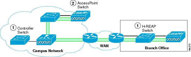
The definition of an access switch is slightly different in the Unified Wireless solution, because three locations can be considered an access switch:
•
•
•
These locations are illustrated in Figure 9-17.
Figure 9-17 Access Switches
The connections of interest in the CISF discussions are the controller switch and the H-REAP switch. The AP switch is not discussed because WLAN traffic does not terminate on this switch, and the AP simply appears as a single device connected to that switch port, so from a security point of view it can be considered an access client.
Note
The scope of these investigations is limited to attacks between wireless users, because of the recommended design guidance that wireless and wired users should be kept on separate subnets, and discussing attacks across subnet boundaries is beyond the scope of this discussion.
The three following scenarios are considered:
•
•
•
For Scenario 1, in which both attacker and target are associated to the same AP, the traffic remains local to the H-REAP or WLC, and CISF is not useful. In this case, explore other alternatives are explored to mitigate the effects of the attacks. The second and third scenarios are the ones in which CISF can be effective.
For enterprise WLAN deployment, Cisco recommends the use of multiple VLANs per SSID. This requires configuring an 802.1q trunk between the Fast Ethernet port on the AP and the corresponding port on the access switch. With multiple VLANs defined, the administrator can keep the data traffic separated from the AP management traffic. The company security policy is also likely to require having different types of authentication and encryptions for different type of users (open authentication and no encryption for guest access, dot1x authentication and strong encryption for employees, and so on). This is achieved by defining multiple SSIDs and VLANs on the AP.
Given the above, the example configurations use a trunk connection between the WLC or H-REAP AP and the access switch.
CISF for Wireless Application
This section describes each of the features provided within CISF that were tested for protection against wireless attacks, and includes the following topics:
•
•
•
•
•
Using Port Security to Mitigate a MAC Flooding Attack
This section describes how to use CISF port security to mitigate a MAC flooding attack. It includes the following topics:
•
•
•
Port Security Overview
Port security sets a maximum number of MAC addresses allowed on a port. You can add addresses to the address table manually, dynamically, or by a combination of the two. Packets are dropped in hardware when the maximum number of MAC addresses in the address table is reached, and a station that does not have a MAC address in the address table attempts to send traffic.
Enabling port security on the access port of the switch stops a MAC flooding attack from occurring because it limits the MAC addresses allowed through that port. If the response to a violation is set to shutdown, the port goes to error-disable state. If the response is set to restrict, traffic with unknown source MAC addresses are dropped.
Port Security in a Wireless Network
It is not generally recommended to enable port security on a switch port connected to an H-REAP AP or WLC. The use of port security implies knowing the exact number of MAC addresses that the switch learns and allows from that port; in the case of an H-REAP AP or WLC, the various source MAC addresses that the switch learns usually correspond to wireless users. Setting port security on the switch port allows only a certain number of users on the wired network.
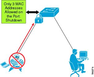
For example, a company might have a security policy that allows only certain MACs, and a certain number of them, to send traffic through the access point. In this case, a combination of MAC filtering on the H-REAP AP or WLC and port security on the switch ensures that only the selected users access the wired network. Most of the time, however, a company implements a WLAN to facilitate the mobility of the employees, which implies that an H-REAP AP or WLC, at any given time, does not have a predetermined number of users associated with it. In all cases in which it is impossible to determine the number of users connected to the AP, enabling port security on the switch port brings no advantages. At worst, it can create an involuntary DoS attack; if the policy for port security is set to shut down the port in the case of a violation, when this happens, all the users connected to that AP lose network connectivity. Figure 9-18 shows an example of using port security to limit a wireless MAC flooding attack by locking down the port and sending an SNMP trap.
Figure 9-18 Using Port Security
Effectiveness of Port Security
Even if port security is not an option to stop this attack (as explained), the MAC flooding attack is unsuccessful when launched by a wireless user. The reason for this is the 802.11 protocol itself. The association to an AP is MAC-based; this means that the AP bridges (translational bridge) traffic coming only from or going to known users or known MACs. If a MAC flooding attack is launched from a wireless user, all the 802.11 frames with random source MAC addresses that are not associated to the AP are dropped. The only frame allowed is the one with the MAC of the malicious user, which the switch has probably already learned. Thus, the operation of the access point prevents the switch from being susceptible to MAC flooding attacks.
Using Port Security to Mitigate a DHCP Starvation Attack
This section describes how to use CISF port security to help prevent a DHCP starvation attack. It includes the following topics:
•
•
•
Overview
For wired access, port security can currently prevent a DHCP starvation attack launched from a PC connected to a switch and using a tool such as Gobbler. The failure of the attack is due more to a limitation of the tool than an actual fix provided by port security. The only reason such an attack fails is that
Gobbler uses a different source MAC address to generate a different DHCP request; if the attacker used his or her MAC address in the Ethernet packet and simply changed the MAC address in the DHCP payload (the field is called chaddr), port security would not stop the attack.
All that can currently be done is to try to slow down the attack using a DHCP rate limiter on the switch port. The next software release for the Catalyst switches will provide the fix for such attack: the switch will need to compare the source MAC address of the DHCP request with the MAC address in the DHCP payload and drop the request if the two are different. This fix assumes that the DHCP server is connected to the wired infrastructure, so it will be useful if the DHCP server feature available on the AP is used.
Wireless DHCP Starvation Attack
In a Unified Wireless deployment, the vulnerability to a DHCP starvation attack depends on whether the WLC terminates the user traffic or an H-REAP terminates the user traffic.
The WLC protects the network from DHCP starvation attacks because it examines DHCP requests to ensure that the client MAC address matches the chaddr. If the addresses do not match, the DHCP request is dropped.
In case the H-REAP VLAN is terminated locally, the DHCP request does not go through the controller and an analysis of the chaddr cannot performed. In this case, the same considerations related to this attack for wired access also apply when the attacker launches the attack via wireless. A smart attacker uses the MAC address with which he or she is associated to the AP to generate the random DHCP requests, simply changing the requesting MAC address in the DHCP packet payload. To the AP, the packet looks like a valid packet coming in from one associated client and it does not drop it.
Using DHCP Snooping to Mitigate a Rogue DHCP Server Attack
This section describes how to use DHCP snooping to mitigate a DHCP server attack. It includes the following topics:
•
•
•
Overview
DHCP snooping is a DHCP security feature that provides security by building and maintaining a DHCP snooping binding table and filtering untrusted DHCP messages. It does this by differentiating between untrusted interfaces connected to the end user and trusted interfaces connected to the DHCP server or another switch. End-user ports can be restricted to sending only DHCP requests and no other type of DHCP traffic. Trusted ports allow any DHCP message to be forwarded. The DHCP snooping table is built per VLAN and ties the IP address/MAC address of the client to the untrusted port. Enabling DHCP snooping prevents users from connecting a non-authorized DHCP server to an untrusted (user-facing) port and start replying to DHCP requests.
DHCP Snooping for Wireless Access
The WLC manages all DHCP requests from clients and acts as a DHCP relay agent. DHCP requests from WLAN clients are not broadcast back onto the WLAN, and they unicast from the WLC to the configured DHCP server. This protects the WLAN clients connected to the WLC from rogue DHCP server attacks.
Clients connected to an H-REAP native interfaces are not protected against rogue DHCP server attacks by the WLC.
Keep in mind that the CISF features (in this case DHCP snooping) are available on the switch and not on the AP, so they intercept the malicious messages only if the traffic from the rogue server goes through the switch.
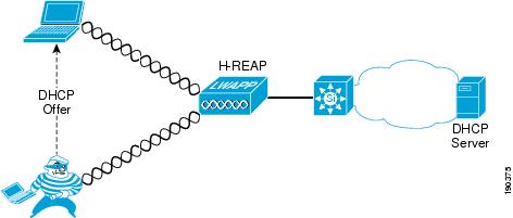
Figure 9-19 shows an example of using DHCP snooping to mitigate against a rogue DHCP server attack, and how the attack can happen before the switch provides DHCP protection.
Figure 9-19 Security Used Against Rogue DHCP Server Attack
Effectiveness of DHCP Snooping
DHCP snooping is enabled on a per-VLAN base, so it works on a trunk port. A separate DHCP snooping entry is inserted for each DHCP request received on the same trunk port for clients in different VLANs. The fact that DHCP snooping works for a trunk port is very important because it makes this CISF feature applicable to a WLAN deployment in which multiple SSIDs/VLANs are requested on the H-REAP native interfaces. If the DHCP snooping attacker is associated to a different H-REAP, the switch is able to protect against the attack. However, if the attacker and the target are associated to the same H-REAP, the attack does not go through the switch and the attack is not detected.
DHCP snooping also provides some protection against DHCP server attacks by rate limiting the DHCP requests to the DHCP server.
Using Dynamic ARP Inspection to Mitigate a Man-in-the-Middle Attack
This section describes how to use Dynamic ARP Inspection (DAI) to mitigate ARP spoofing MIM attacks. It includes the following topics:
•
•
•
Overview
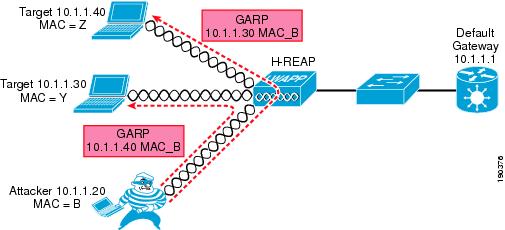
DAI is enabled on the access switch on a per-VLAN basis and compares ARP requests and responses, including gratuitous ARPs (GARPs), to the MAC/IP entries populated by DHCP snooping in the DHCP binding table. If the switch receives an ARP message with no matching entry in the DHCP binding table, the packet is discarded and a log message is sent to the console. DAI prevents ARP poisoning attacks that may lead to MIM attacks such as those launched using ettercap (an example of a tool that has a very intuitive user interface) by stopping the GARP messages that the malicious user sends to the target to alter their ARP table and receive their traffic. The ARP messages are filtered directly at the port to which the attacker is connected.
DAI for Wireless Access
The WLC protects against MIM attacks by performing a similar function to DAI on the WLC itself. This allows it to block the GARPs necessary for this attack to proceed. DIA should not be enabled on the WLANs behind the WLCs, because the WLC uses the GARP in Layer 3 roaming for clients.
For the H-REAP, two different scenarios can impact the effectiveness of the DAI feature on the switch. It is possible to have DAI enabled on all the VLANs carried on the trunk from the AP to the switch. This makes the CISF feature applicable in a wireless environment in which multiple SSIDs/VLANs are deployed on the AP. The following scenarios assume the attacker to be associated to an AP and Layer 2 adjacent to the targets:
•
•
These different scenarios determine in which cases the traffic goes through the switch and thus can be stopped.
In Scenario 1, the MIM attack attempts to use a GARP to change the ARP table entries on the default gateway and the wireless victims, redirecting traffic to go through the attacker. DAI can block the GARP at the default gateway, but has no impact on the GARP to the wireless client. This limits the effectiveness of the MIM attack.
In Scenario 2, the MIM attack sends GARPs to wireless clients, and the switch implementing DAI does not see these GARPs and cannot block the attack.
Figure 9-20 shows an example of the attack mechanism where GARPs are sent to the two IP connection nodes on the subnet to divert the traffic between them.
Figure 9-20 Dynamic ARP Inspection
Effectiveness of DAI
The attack is completely successful only in the example of Figure 9-20 in which the traffic remains local to the H-REAP and never goes through the switch. Usually the interesting traffic for an attacker, such as passwords and account information, travels from the wireless client to the wired network (server or Internet), so this is not too harmful.
The scenario where the default gateway and a wireless client are the attack targets can be called a half duplex MIM attack. Ettercap is able to modify the ARP table of the wireless user that is now sending all the traffic to the intruder, but the GARP to the default gateway is intercepted by the switch and a message is logged, as shown in the following example:
4507-ESE#sh ip arp inspection logTotal Log Buffer Size : 32Syslog rate : 5 entries per 1 seconds.Interface Vlan Sender MAC Sender IP Num of Pkts Reason---------- ---- -------------- --------------- ----------- ------Fa3/26 20 00d0.5937.7acc 10.20.1.100 1(11:07:48 PDT Wed Feb 3 2003) DHCPDenyFa3/26 20 00d0.5937.7acc 10.20.1.100 1(11:07:48 PDT Tue Feb 3 2003) DHCPDenyFa3/26 20 00d0.5937.7acc 10.20.1.100 1(11:07:48 PDT Tue Feb 3 2003) DHCPDenyFa3/26 20 00d0.5937.7acc 10.20.1.100 1(11:07:48 PDT Tue Feb 3 2003) DHCPDenyFa3/26 20 00d0.5937.7acc 10.20.1.100 1(11:07:48 PDT Tue Feb 3 2003) DHCPDenyFa3/26 20 00d0.5937.7acc 10.20.1.100 1(11:07:48 PDT Tue Feb 3 2003) DHCPDenyFa3/26 20 00d0.5937.7acc 10.20.1.100 1(11:07:48 PDT Tue Feb 3 2003) DHCPDenyFa3/26 20 00d0.5937.7acc 10.20.1.100 1(11:07:48 PDT Tue Feb 3 2003) DHCPDenyFa3/26 20 00d0.5937.7acc 10.20.1.100 1(11:07:48 PDT Tue Feb 3 2003) DHCPDenyFa3/26 20 00d0.5937.7acc 10.20.1.100 1(11:07:48 PDT Tue Feb 3 2003) DHCPDenyInterface Vlan Sender MAC Sender IP Num of Pkts Reason---------- ---- -------------- --------------- ----------- ------Fa3/26 20 00d0.5937.7acc 10.20.1.100 1(11:07:49 PDT Tue Feb 3 2003) DHCP DenyBecause the MAC address is provided in the log, the administrator can take further action to block the attack by disassociating the attacker.
When DAI is configured on the VLAN, an ARP rate limiter is configured globally to prevent flooding of ARP requests coming from a certain port. The default value of the rate limiter is 15 packets per second (pps). If this limit is reached, the switch disables the port to prevent the attack. In this case, to launch a MIM attack, an attacker must first discover who else is Layer 2 adjacent. To do this, ettercap generates a series of GARPs, claiming to be each one of the IP address on the subnet. In this way, the real owner of that address replies and ettercap can build its table.
In lab tests, this limit has been reached immediately by ettercap and the port shut down. This is acceptable in a wired scenario, but in a wireless scenario, by shutting down the port connected to the AP, all the wireless users lose their connection to the outside world and a possible MIM attack turns into a DoS attack.
To avoid this involuntary attack created by enabling DAI, Cisco recommends turning off the ARP rate limiter on the port of the switch connected to the AP. You can do this with the following interface level command:
ip arp inspection limit noneAn alternative is to change the threshold value to a value larger than 15 pps. However, this is not a general remedy because it depends on the implementation of the specific tool being used to launch the attack.
Using IP Source Guard to Mitigate IP and MAC Spoofing
This section describes how to use IP Source Guard to mitigate IP and MAC spoofing. It includes the following topics:
•
•
•
Overview
When enabled on an interface of the access switch, IP Source Guard dynamically creates a per-port access control list (PACL) based on the contents of the DHCP snooping binding table. This PACL enforces traffic to be sourced from the IP address issued at DHCP binding time and prevents any traffic from being forwarded by other spoofed addresses. This also prevents an attacker from impersonating a valid address by either manually changing the address or running a program designed to do address spoofing, such as hping2. This feature has an option (port security) to filter the incoming address, also using the MAC address in the DHCP snooping binding table.
The attacker typically uses the spoofed address to hide his or her real identity and launch an attack, such as a DoS attack, against a target.
IP Source Guard for Wireless Access
In the case of wireless access, IP Source Guard can be enabled on the trunk port connecting the access switch to the IP. This allows the switch to filter any traffic coming from wireless users that does not match an entry in the DHCP binding table.
IP Source Guard does not need to be enabled on the VLANs behind a WLC, because the WLC performs a similar function to ensure that the IP address used by a client is the IP address that has been assigned to that client.
IP Source Guard is applicable to the H-REAP because it does not maintain a check on WLAN client MAC address IP address bindings.
In tests, the following two scenarios were considered:
•
•
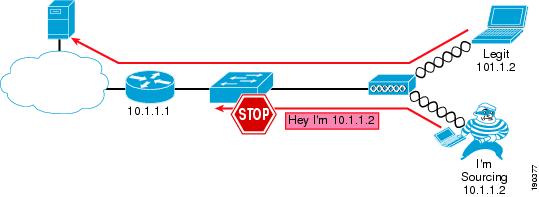
Figure 9-21 shows an example of using IP Source Guard to mitigate IP and MAC spoofing attacks.
Figure 9-21 IP Source Guard Preventing MIM
Effectiveness of IP Source Guard
The effectiveness of this feature depends on two factors: the way the attacker is able to spoof the address, and which scenario is being tested.
The association to the AP is based on the MAC address, so if the AP receives a frame with an unknown source address, it drops the frame. When launching an IP spoofing attack, the attacker has the option to use his or her own MAC address or to use one from another user connected to the same AP. All the other combinations, such as using a random MAC address or using the MAC address of a user connected to another AP, lead to a failed attack because the AP drops the frame.
In case the attacker uses his or her own MAC address but spoofs the IP address, IP Source Guard enabled on the switch stops the attack in all the scenarios described above except the first. In the first scenario, the traffic stays local to the AP and the CISF feature never kicks in. In the other scenarios, CISF successfully stops the attack because the IP-spoofed packet sent by the malicious user has no entry in the DHCP snooping table.
However, if the attacker is able to spoof both the MAC and the IP address of another wireless user connected to the same AP, basically assuming the identity of another user, then the attack is successful even in Scenarios 2 and 3.
Spoofing both the Mac and IP address is realistically possible in a hot spot environment where no encryption is used, or when the weaknesses of Wired Equivalent Privacy (WEP) are exploited. It has been shown in tests that you need to passively listen to only six million packets to break the encryption mechanism used by WEP.
This is one of the reasons why Cisco highly recommends the use of strong encryption whenever possible, preferably dynamic keys with TKIP and MIC, to make it harder for the attacker to break the encryption and use the key, IP address, and MAC address of another user to launch an attack.
Summary of Findings
The results of the tests are presented in Table 9-1.
Note that Cisco tested only those attacks that are targeted by the CISF features on wired access, and it was always assumed that the attacker was wireless, while the target could be either wired or wireless depending on the scenario considered. Finally, the solution reported in Table 9-1 represents what is currently available using the CISF features on the access switch; when those features do not help, Cisco proposes an alternative solution using features available directly on the access point.
Conclusion
CISF, or at least some of its features, should ideally be implemented on the edge device that provides access to the endpoints. In the case of wireless access, this device is the AP and not the access switch connected to the AP.
As proven by the lab tests, enabling CISF on the access switch still helps prevent or mitigate many of the attacks for which these features were designed. However, the major limitation of this implementation is the failure to stop attacks in which the traffic does not traverse the switch. If the traffic does not pass through the switch, the CISF feature is not activated and does not protect the target.