Downloads |
 Feedback Feedback
|
Table Of Contents
VPN Ports and LAN-to-LAN Tunnels
Tunnel Partner: VPN Configuration Dialog Box
Interoperability Settings Dialog Box
VPN Ports and LAN-to-LAN Tunnels
A VPN port is a virtual port which handles tunneled traffic. Tunnels are virtual point-to-point connections through a public network such as the Internet.
All packets sent through a VPN tunnel are IP-encapsulated packets, including AppleTalk, IPX and even IP packets. This encapsulation is added or removed, depending on the direction, by "Tunnel Partner" routers. Once a packet reaches the remote Tunnel Partner, the TCP/IP encapsulation is stripped off, leaving the original protocol. The unencapsulated packet is then handled according to the VPN port's protocol configuration settings.
Networks connected via a tunnel will communicate as if they are on the same network, even though they are separated by the Internet.
Add VPN Port Dialog Box
This section configures VPN tunnel parameters and defines a virtual port for LAN-to-LAN tunnel traffic.
VPN (Virtual Private Network) ports are added to the edit area of a device by right-clicking on any configuration item for the device, then choosing VPN Port/Add VPN Port from the popup menu.
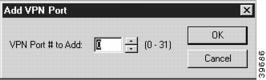
The Add VPN Port dialog box (Figure 6-1) will open in the Main Window and will allow you to select a number for the port. To delete a VPN port, right-click on the port's icon, then choose VPN Port/Delete VPN Port. These functions are also available in the File menu.
Figure 6-1 Add VPN Port Dialog Box
Tunnel Partner: VPN Configuration Dialog Box
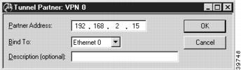
Once you have created a VPN port, you may access the Tunnel Partner: VPN Configuration dialog box (Figure 6-2) by clicking on the port's icon and selecting VPN Tunnel Partner.
Remember that you must set up both ends of every tunnel. Therefore, you must repeat this setup with the remote router.
Figure 6-2 Tunnel Partner: VPN Configuration Dialog Box
Partner Address
Enter the IP address of the remote Tunnel Partner with which this VPN port will communicate via the tunnel. This will be an interface on the remote router which has been set to route IP and will also be the remote VPN port's Bind To interface.
Bind To Interface
Tunnel Partner devices must know each other's IP address in order to correctly address the packets destined for the far end of the tunnel. This device's tunnel end must have an IP address so that the Tunnel Partner can address packets to it. Use the pull-down menu to select an interface on this device which has been set to route IP.
Description
This box allows the use to enter a description of the Tunnel Partner. The description can be an IP address or an alphanumeric name.
If both Ethernet ports are being used on a VPN 5000 concentrator, the Bind To port must be set to Ethernet 1.
You must enter the IP address for the interface you selected here into the Tunnel Partner dialog box of the Tunnel Partner routers.
IKE Key Management
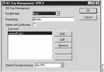
Once you have created a VPN port, you may access the IKE Key Management dialog box (Figure 6-3) by clicking on the port's icon and selecting IKE Key Management.
Figure 6-3 IKE Key Management Dialog Box
This dialog box sets the Internet Security Association Key Management Protocol/Internet Key Exchange (ISAKMP/IKE) parameters. These settings control how each tunnel partner will identify and authenticate each other.
Key Manage
The options for the Key Manage drop-down menu are:
•
If Auto key management is selected, IKE will be used to allow two devices to negotiate between themselves what type of encryption and authentication to use for the tunnel. The Auto setting should only be used when the tunnel partner is another Cisco VPN 5000 series device.
•
•
•
Shared Key
This is a shared alphanumeric secret between 1-255 characters long. It is used to generate session keys which are used to authenticate and/or encrypt each packet received or sent through the tunnel.
Transform
This list box specifies the protection types and algorithms which will be used for tunnel sessions. Each option is a protection piece which specifies the authentication and/or encryption parameters to be used.
Use the Move Up and Move Down buttons to arrange the priority of the protection options.
Perfect Forward Secrecy
Perfect Forward Secrecy (PFS) allows you to add an additional security parameter to tunnel sessions. PFS means that every time encryption and/or authentication key are computed, a new Diffie-Hellman Key Exchange is included.
Diffie-Hellman Key Exchange uses a complex algorithm and public and private keys to encrypt and then decrypt tunneled data. Adding PFS to a tunneled session greatly increases the difficulty of finding the session keys used to encrypt a VPN session. It also means that even if the keys are somehow cracked, only a portion of the traffic is recoverable.
•
•
•
•
•
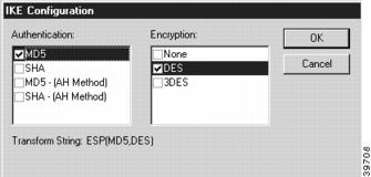
To add, remove, or edit a Transform, you must access the IKE Configuration dialog box (Figure 6-4) by selecting the Add..., Remove..., or Edit... buttons.
Figure 6-4 IKE Configuration Dialog Box
Authentication
This set of checkboxes specifies the authentication algorithm to be used for the negotiation. MD5 is the Message-Digest 5 hash algorithm. SHA is the Secure Hash Algorithm.
Choosing either of the top two checkboxes means that the Encapsulating Security Payload (ESP) header will be used to encrypt and authenticate packets.
Choosing either of the bottom two checkboxes specifies that the Authentication Header (AH) will be used to authenticate packets.
Encryption
This set of checkboxes specifies the encryption algorithm. DES (Data Encryption Standard) uses a 56-bit key to scramble the data. 3DES uses three different keys and three applications of the DES algorithm to scramble the data.
You may choose only one authentication and one encryption method. The default setting of ESP (MD5,DES) is recommended for most setups.
Manual Key Management
Once you have created a VPN port, you may access the Manual Key Management dialog box (Figure 6-5) by clicking on the port's icon and selecting Manual Key Management.
This dialog box sets encryption parameters for non-IKE tunnels.
Figure 6-5 Manual Key Management Dialog Box
.
Enable Authentication
This checkbox controls whether all tunnel traffic will be authenticated.
•
Authentication Method
If Authentication has been enabled, MD5 will appear here and packet-by-packet authentication will be done using the Authentication Secret.
Authentication Secret
This secret is used to generate session keys which are used to authenticate each packet received from or sent through the tunnel. The secret can be from 1 to 255 characters in length.
Enable Encryption
This checkbox controls whether all tunnel traffic will be encrypted.
•
Encryption Method
This pull-down menu allows an encryption method to be specified.
•
•
•
•
•
Some VPN devices may not allow 3DES as an option.
Encryption Secret
This secret is used to generate session keys which are used to encrypt/decrypt each packet received from or sent through the tunnel. The secret can be from 1 to 255 characters in length.
PLE, DES56 and 3DES all require that the same Encryption Secret be configured for each end of the tunnel.
Interoperability Settings Dialog Box
This dialog box (Figure 6-6) enables the concentrator to interoperate with other vendors' devices. If the remote Tunnel Partner is a Cisco VPN 5000 series device, it is not necessary to configure these settings. Interoperability settings are individually set for each tunnel partner.
To access this dialog box, select VPN Port #/Interoperability Settings from the Device View.
Figure 6-6 Interoperability Settings Dialog Box
Mode
This pull-down menu set the IKE Phase 1 negotiation mode between the devices. Phase 1 controls how the two devices identify and authenticate each other so that tunnel sessions can be established.
Main and Aggressive are the two IPsec standard methods for performing the Phase 1 negotiation. This setting must match the Phase 1 negotiation mode of the remote peer. Other vendors may support only the Main mode.
Local and Peer Settings
As part of their interoperability function, the following settings specify access from one area behind a VPN device to another area behind a VPN device.
The Local settings specify what local subnets, hosts, ports and/or protocols will be reachable via the tunnel.
The Peer settings specify which remote subnets, hosts, ports and/or protocols will be reachable via the tunnel. The remote tunnel partner (i.e., peer) must have a matching policy in order for traffic to be successfully tunneled.
Local / Access
This is used to specify a local host or subnet which will be reachable by the tunnel. It is entered as an IP address followed by a slash followed by the number of significant bits in the entered IP address (i.e., 192.168.41.9/32). To allow access to only a single host, specify 32 in the bits portion.
Local / Protocol
The pull-down menu is used to specify an IP protocol which will accepted by this end of the tunneled. The default of 0 will allow all protocols. Accepted IP Protocol numbers are:
•
•
•
•
•
•
•
Local / Port
The is used to specify a local port number which will be reachable via the tunnel. The default of 0 will allow all ports.
Refer to the IP Filter Name section in the Text Based Configuration and Command Line Management Reference Guide for more information on commonly used ports and their numbers.
Peer / Access
This is used to specify a host or subnet behind the remote tunnel partner which will be reachable via the tunnel. It is entered as an IP address followed by a slash followed by the number of significant bits in the entered IP address (i.e., 192.168.41.9/32). To tunnel to only a single host, specify 32 in the bits portion.
Peer / Protocol
This pull-down menu is used to specify an IP protocol which will be tunneled. If a protocol number is specified, then only traffic of that protocol type will be tunneled. The default of 0 will allow all protocols. Accepted IP Protocol numbers are:
•
•
•
•
•
•
•
Peer / Port
This is used to specify a port number. If a Peer Port number is specified, then only traffic destined for that particular port will be tunneled. The default of 0 will allow all ports.
Refer to the IP Filter Name section in the Text Based Configuration and Command Line Management Reference Guide for more information on commonly used ports and their numbers.