Downloads |
 Feedback Feedback
|
Table Of Contents
OSPF Packet Authentication Key
OSPF Configuration
This chapter provides instructions for configuring a network utilizing the OSPF (Open Shortest Path First) Protocol. OSPF uses a link-state algorithm in order to build and calculate the shortest path to all known destinations. Each router in an OSPF area contains an identical link-state database, which is a list of each router's usable interfaces and reachable neighbors.
Unlike RIP updates, OSPF link-state database updates are only sent when routing changes occur, instead of periodically, and the link-state database is updated instantly, rather than gradually, as stale information is timed out.
OSPF routing decisions are based on "cost" which is an indication of the overhead required to send packets across a certain interface. The cost of an interface is calculated based on link bandwidth rather than the number of hops to the destination. The cost can also be configured to specify preferred paths.
OSPF Dialog Box
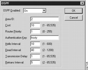
To access this dialog box (Figure 15-1), select the interface you wish to configure (Ethernet, WAN, VPN) from the device view, select TCP/IP Routing, then click on the OSPF option button. OSPF must be configured for each interface on which you want to run OSPF.
The router will automatically be in the Backbone area, area 0, on each interface. It is also necessary to add configuration information for an interface to be assigned to a non-backbone area.
Figure 15-1 OSPF Dialog Box
OSPF Enabled
This pull-down menu sets how the interface will function on a network utilizing OSPF.
•
If On is specified, the interface will serve as an active interface on an OSPF network. The router will establish adjacencies with other routers. Adjacent routers exchange database information with the Designated Router, which then floods the information to all other routers in their area.
•
A Passive interface will have its network advertise to other OSPF networks. This can be used to have a non-OSPF interface's network advertised into OSPF. A Passive interface must also be associated with an OSPF Area.
•
Area ID
This sets the area to which this interface belongs. An area is a generalization of an IP subnetted network. It can be specified as a number between 0 and 0xFFFFFFFF, or as an IP address in dotted-decimal notation. Area 0 is the backbone area and is the default setting.
Cost
This number specifies the priority of one particular path over another path. An OSPF router will choose the gateway with the lowest cost to enter into its routing table. To give preference to a path, set a lower cost on that interface. The value can be a number between 1 and 65,535.
Router Priority
This number sets the router priority and is only used on multi-access networks such as LANs. This establishes whether the router is eligible to become the Designated Router for the LAN. The value for OSPF Router Priority can be a number between 0 and 255.
At least one router on a LAN must have a priority greater than 0 in order for OSPF to work, since there must be a Designated Router.
The Designated Router is the single router within an area which broadcasts the Link State Advertisement for the area. A priority of 0 means that the router is not eligible. The router with the highest priority becomes the Designated Router.
If a router with a lower priority is the Designated Router and a new router with a higher priority comes online, the Designated Router will not change.
Authentication Key
This string sets the OSPF packet Authentication Key. The string can be between one and eight alphanumeric characters.
In order to use authentication, the OSPF Authentication Type for this interface should be set to Simple. This is set in the OSPF Area dialog box discussed in the "OSPF Area" section.
Hello Interval
This value sets the interval, in seconds, that the router sends out OSPF keepalive packets which let other routers know the router is up.The value must be greater than one. The default settings of 10 seconds for a LAN and 30 seconds for a point-to-point connection are recommended for most applications.
Dead Interval
This value sets the length of time, in seconds, that OSPF neighbors will wait without receiving an OSPF keepalive packet from a neighbor before assuming the router is down. This value must be at least twice the value of Hello Interval.
Each connected router must have the same values for Hello Interval and Dead Interval or the routers will not be able to communicate. If you change the defaults on one router, you must change them on all attached routers within an area.
Transmission Delay
This value sets the amount of time added to the age of OSPF Link State Update packets before transmission. It is the estimated number of seconds to transmit a packet over the interface.
Retrans Interval
This value sets the interval, in seconds, between retransmission of Link State Update packets. The value must be between 2 and 65,535.
OSPF Area
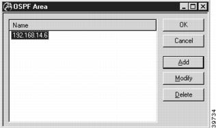
This dialog box (Figure 15-2) defines a list of OSPF Area names. An area is a generalization of an IP subnetted network within an Autonomous System (AS). An AS is a collection of networks under a common administration sharing a common routing strategy.
All routers within an area have the same link-state database. An interface can only belong to one area, although different interfaces on a router can belong to different areas, making the router an Area Border Router. Area Border Routers disseminate routing information or routing changes between areas.
Figure 15-2 OSPF Area Dialog Box
You can access the OSPF Area dialog box by selecting OSPF/OSPF Area from the device view.
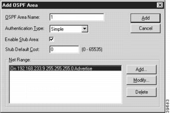
To add or modify the entries, select the appropriate button to access the Add OSPF Area dialog box (Figure 15-3).
Figure 15-3 Add OSPF Area Dialog Box
OSPF Area Name
The OSPF Area Name is an integer or IP address. If more than one area is configured within an AS, then one of these areas has to be area 0, which is the backbone. The backbone has to be physically connected to all other areas. It is recommended that you start with area 0 and then expand into other areas.
The only exception to starting with area 0 is with virtual links, which are explained in the following section.
Authentication Type
This pull-down box specifies whether the router will perform authentication of Link State Advertisements received from other routers.
•
•
Enable Stub Area
This checkbox sets whether this area will function as a stub area. A stub area is an area which cannot receive external advertisements, which means RIP or static routes will not be redistributed into this area.
If routing from a stub area to external routes (i.e., non-OSPF routes) is needed, a default route must be set. A stub area may not be a transit area for a virtual link.
The backbone area (area 0) cannot be designated as a stub area.
Stub Default Cost
This value sets the cost of the default route which will be used by routers within the stub area to route to external destinations. The value must be a number between 0 and 65,535.
Net Range
The Net Range can be used to consolidate routing information at area boundaries, or to hide routing information from routers outside the area. Net Ranges only apply to inter-area networks. If all the routers are in one area, any defined Net Ranges will not be used by the router. You may specify several different Net Ranges.
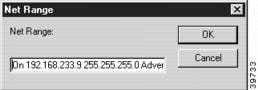
To add or modify a Net Range, click the appropriate button to open the Net Range dialog box (Figure 15-4).
Figure 15-4 Net Range Dialog Box
The Net Range string has the following syntax:
{On|Off <IP Address> < IP Subnet Mask> Advertise|DoNotAdvertise}•
•
•
•
DoNotAdvertise only applies to OSPF routes and not to routes learned from external protocols using IP route redistribution. External routes must be excluded by using route filtering.
OSPF Virtual Link
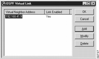
This dialog box (Figure 15-5) displays a list of all IP addresses being used for virtual neighbors. Configuring a virtual link is the only way to allow an area which is not contiguous to the backbone area (area 0) to operate.
The virtual link must be configured in both routers which are providing the tunnel to the backbone. These two routers do not need to be physically connected, but they must share a common area called the transit area. (The transit area is designated in the Add OSPF Virtual Link dialog box.)
Figure 15-5 OSPF Virtual Link Dialog Box
To access the OSPF Virtual Link dialog box, select OSPF/OSPF Virtual Link from the device view.
To add or modify the entries, select the appropriate button to access the Add OSPF Virtual Link dialog box (Figure 15-6).
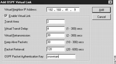
Figure 15-6 Add OSPF Virtual Link Dialog Box
This dialog box defines configuration parameters for an OSPF Virtual Link.
Virtual Neighbor IP Address
The virtual neighbor IP address is the largest IP address associated with the router used for the virtual link.
Enable Virtual Link
This checkbox will specify whether an OSPF virtual link will operate. When checked, it will activate the virtual link.
Transit Area
The transit area is the number assigned to the tunnel between the two routers of the virtual link. Each router must have at least one interface attached to the transit area. The transit area can be specified as a number between 0 and 0xFFFFFFFF, or as an IP address.
Virtual Transit Delay
The virtual transit delay sets the amount of time added to the age of Link State Update packets before transmission. It is the estimated number of seconds to transmit a packet over the virtual link. The numeric value can be between 2 and 65,535 seconds.
Virtual Retransmission
The virtual retransmission value sets the interval, in seconds, between retransmission of the Link State Update packets across the virtual link. The value can be between 2 and 65,535 seconds.
Keep Alive Packets
The keepalive value sets the interval, in seconds, that the router sends out "keepalive" packets across the virtual link to let the other end of the link know the router is up. The value must be greater than 10 seconds.
Packet Retrieval
The packet retrieval value sets the length of time, in seconds, that this router will wait without receiving a "keepalive" packet from the other end of the virtual link before assuming it's down. The packet retrieval value must be at least twice that of the keepalive packet value. The default value is 4 times the keepalive packet value.
The KeepalivePacket and Packet Retrieval values for each end of the virtual link must match or the virtual link will not function.
OSPF Packet Authentication Key
This string sets the OSPF Authentication key for the virtual link. The string may be between one and eight alphanumeric characters.
The authentication key must be the same for both ends of the virtual link.