Downloads |
 Feedback Feedback
|
Table Of Contents
Static Routes & Routing Protocols
Non-extended and Extended AppleTalk Networks
Multiport Bridges/Switches and "Bridge Groups"
Local Management Interface (LMI)
Encapsulation and Fragmentation
Network/Protocol Addressing and Virtual Interfaces
IP Networking Basics
IP 101
This is a very brief introduction to IP networking. For more in-depth information, there are a number of excellent references. In particular, Douglas Comer's Internetworking with TCP/IP (Prentice Hall) is one of the standard references and provides a wealth of information on the subject.
IP Addresses
Each device on an IP network requires 3 different pieces of information in order to correctly communicate with other devices on the network: an IP address, a subnet mask, and a broadcast address. You will usually see each of these numbers written as four "octets" (e.g. 198.41.12.151, 255.255.255.0, and 198.41.12.255).
Every IP address is really made up of two pieces: a "network" portion, which tells routers what group of devices a packet should go to (e.g., any, a campus, etc.) and a "host" portion which tells routers what specific device among that group the packet should go to.
By examining the destination address in an IP packet that must be forwarded, and by using information that has either been statically configured or dynamically gathered from other routers, any router can determine the optimal path for forwarding packets from one group to another.
Each group of devices on an IP internet needs to have a unique network portion, and each device within that group also needs a unique host portion. In the case of the Internet, this uniqueness is made possible by indirectly getting all network portion assignments through a central clearinghouse called the Network Information Center or "NIC." The NIC assigns blocks of addresses to Internet Service Providers (ISPs), who then assign these addresses to their customers.
If your network is, or will be, connected to the Internet, you will need to get a unique network address from your ISP or network administrator.
How much of any given address is the network part and how much is the host part is determined by the "class" of the network. In each case, the part of the address not used for the network portion is left as the host portion.
Table A-1 describes how IP address classes are organized.
Table A-1 IP Address Classes
A
from 1.0 to 127.0
approx. 16 million
B
from 128.0 to 191.255
65,536
C
from 192.0 to 223.255.255
255
You can always tell what class an address is by looking at the first octet and comparing it to the chart above. For instance, the address at the top of this appendix has 198 as the first octet, so it is Class C.
Subnet Masks
A subnet mask tells a router how much of an address it should treat as the network portion. The masks for traditional Class A, B and C networks are shown below in Table A-2
Table A-2 Standard IP Subnets
Comparing the masks above to the first chart, you can see that the 255s in a mask identify the network portion of the address.
Just as the masks above specify what portion of the global IP address range a network is using, a subnet mask can also be used to subdivide a Class A, B or C network range into multiple groups of hosts, or "subnets."
This is done by telling the router that more than the traditional number of bits in the mask are to be treated as the network portion of the address. Table A-3 shows all of the possible Class C subnet masks, and how many hosts are then allowed on each subnet.
Table A-3 Subnetted Class C Host Ranges
The lowest calculated address in each range (0 in the traditional C range) is not shown, cannot be used, and is skipped in the chart. The highest address in each range (255 in the traditional C range) is also not shown, and is the broadcast address for the subnet.
With each mask above, the 1s in the binary value represent the network portion, and the 0s represent the host portion (128 is 10000000, 192 is 11000000, etc.). As you use more bits to represent the network portion, fewer bits are left to use as host addresses.
The same idea can be extended to Class A and Class B networks.
Broadcast Addresses
The broadcast address is the address to which devices send packets meant for all other devices. All devices "listen" for broadcasts in addition to their own address. Address Resolution Protocol (ARP) packets and routing information are examples of packets sent to the broadcast address. Most often, the broadcast address is the last address in the network (or subnet) with the host portion being all 1's binary (some networks use 0.0.0.0 or 255.255.255.255, however.). Table A-4 shows some examples of broadcast addresses.
Table A-4 Broadcast Address Examples
The first three entries are traditional Class A, B and C network addresses and use traditional masks. The last two are less traditional, "real world" examples. Note in line 4 the change in the third octet between network address and broadcast address. Line 5 shows what happens when a Class C network has been subnetted.
Assigning an IP address
Use the network portion you were given by your administrator or ISP. Assign the router interface a unique (i.e. unused) host portion. For example, if your ISP tells you your network portion is 198.41.9, you could assign an interface to 198.41.9.1. If you have a router with more than one interface, the network (+ subnet) portions of each port's IP address must be different.
Assigning a Subnet Mask
If you are using traditional Class A, B or C networks, the VPN 5000 Manager will automatically calculate the value for you. If you wish to compute it yourself, use the values in Table A-2.
If you are subnetting, use Table A-3 as a guide for Class C, or follow the same scheme for Class A or B. Note that the IP address for a subnetted interface (including the router interface on that subnet) must be in the correct subnet range, as shown in Table A-3.
Assigning a Broadcast Address
The VPN 5000 Manager will automatically compute the broadcast address for you. If you wish to compute it yourself, use the examples in Table A-4 above as a guide. You can then use the Manager to check your results.
Static Routes & Routing Protocols
In addition to the three required values, you must also decide whether to use an IP routing protocol. Routing protocols are how routers tell each other about networks they are responsible for. Virtually all routers support the IP Routing Information Protocol (RIP).
There are also a variety of other routing protocols which have been developed, some proprietary and some open. A router which is using one of these other protocols can always accept routes using RIP and then supply information about them using the other protocol.
If you choose not to use RIP, or other routers on your network are not broadcasting routing information, you may need to set a default router or define some static routes.
The default router is the place where your router will send any packets addressed to IP networks that it does not know about. With RIP turned off, it will only know about statically configured routes. For very simple IP connections, such as a small network being connected out to the Internet through an ISP, a default route is probably the only routing information needed by your router.
A default router provides a generic location for packets to be sent to, while static routes are more detailed definitions where you specify the route for certain networks, and a "metric" which defines how attractive the route should be considered.
When specifying default routes, you must provide a mask value (as discussed earlier) which tells the router how much of the address you are entering the route for should be considered as the network portion.
IPX 101
This is a very brief introduction to IPX networking. For more in-depth information, there are a number of excellent references. In particular, Rick Sant'Angelo's NetWare Unleashed (SAMS Publishing) provides a good overview of IPX routing along with tips on getting IPX drivers correctly loaded on client machines.
IPX Routing Basics
All routable protocols work by dividing the physical devices on a network into logical groups. A logical group will typically consist of all of the machines on a physical network segment (such as an Ethernet segment).
Each group of devices is assigned a unique "network number" which represents that particular group to all of the routers on the network. Packets which are sent between members of the same group are simply sent directly from one member to another.
Packets which must go between devices belonging to two different groups travel through routers, which forward them along an optimal path.
By examining the destination network number in a packet that must be forwarded, and by using information that routers automatically pass between themselves in IPX Routing Information Protocol (RIP) packets, any router can determine the optimal path for forwarding packets from one group to another.
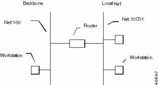
This scheme relies on the fact that each segment is assigned a unique network number. If not, the routers have no way of knowing which of the physical segments with that number should actually receive a packet. Figure A-1 shows an example of IPX routing.
Figure A-1 IPX Routing Example
Among routable network protocols, IPX is relatively simple. Each physical network segment is assigned a network number by the routers on the segment. The network number can be in the range of 1 to FFFFFFFE (that's 8 hexadecimal digits). In the diagram above, 100 and 10C01 are the network numbers for the two segments shown.
Establishing the network number for an IPX network segment is referred to as "seeding" the network. You should generally only have one seed router per network cable segment. It may sometimes be desirable for redundancy to have several seed routers on a segment. This is acceptable as long as all seed routers on the segment are seeding the same network number.
Service Advertising Protocol
Routers participate in allowing end nodes to access IPX services (such as file servers, print servers, communications servers, etc.) by keeping a list of all of the services on an IPX internetwork. This list is maintained by examining the Service Advertising Protocol (SAP) packets which are sent by servers and other routers on the local segment, and by rebroadcasting this information out of their other interfaces.
A "split-horizon" technique is used so that routers do not duplicate information which is already known on the segment being broadcast to.
Client Machine Addressing
Unlike TCP/IP, IPX workstations do not have fixed network/node addresses that need to be configured. Instead, a workstation gets its network number from the router(s) on the segment it is connected to, and uses its Ethernet address for its node number.
This means that an IPX workstation may have as much as 18 hexadecimal digits of network/node address. Fortunately for workstation users, the NetWare client software does the work of discovering the network number and setting the address. Users only need to install Novell drivers to be able to use the IPX protocols over their network.
Routers which support IPX can use any of four "frame types" to send IPX packets. Each frame type organizes the IPX information in a network packet (i.e. frame) in a slightly different fashion. Although the basic information may be the same, clients or servers using different frame types cannot communicate with each other without an intermediate translation occurring between frame types. This translation is called "transitional routing," and is one of the functions that can be performed by routers.
The four IPX frame types are:
•
Ethernet_Type_II
•
•
•
Older versions of NetWare defaulted to the 802.3 Raw frame type, whereas NetWare 4.0 uses the 802.2 frame type.
For this reason, the default configuration for routers which support IPX has both 802.3 Raw and 802.2 set to autoseed (they will come up regardless of whether there is a server on line or not) and the other two frame types set to non-seed (they won't come up unless they "hear" another router using this frame type.
This autoseeding default router configuration simplifies administration of the router since IPX can be routed right out of the box without any configuration. To determine a network number to use for autoseeding, a router listens to the network for several RIP periods, and then examines its routing table (which is filled in with information from RIP packets), and picks an unused number.
AppleTalk 101
This is a very brief introduction to AppleTalk networking. For more in-depth information, the definitive reference is Gursharan Sidhu et al's Inside AppleTalk (Addison-Wesley Publishing). This book provides an in-depth look at the AppleTalk protocol suite and AppleTalk routing.
AppleTalk Routing Basics
All routable protocols work by dividing the physical devices on a network into logical groups. A logical group will typically consist of all of the machines on a physical network segment (such as an Ethernet segment).
Each group of devices is assigned a unique "network number" (or a range of network numbers) which represents that particular group to all of the routers on the network. Packets which are sent between members of the same group are simply sent directly from one member to another.
Packets which must go between devices belonging to two different groups travel through routers, which forward them along an optimal path.
By examining the destination network number in a packet that must be forwarded, and by using information that routers automatically pass between themselves in AppleTalk Routing Table Maintenance Protocol (RTMP) packets, any router can determine the optimal path for forwarding packets from one group to another.
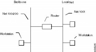
This scheme relies on the fact that each segment is assigned a unique network number/range. If not, the routers have no way of knowing which of the physical segments with that number should actually receive a packet. Figure A-2 shows an example of Appletalk routing.
Figure A-2 AppleTalk Routing Example
Each AppleTalk physical network segment is assigned a network number/range by the routers on the segment. The network number (or range of numbers) can be between 1 and 65,279. In Figure A-2, 100-200 is the network range for the backbone, and 1001 is the network number for the local net segment.
Non-extended and Extended AppleTalk Networks
The original AppleTalk specification, which is now referred to as AppleTalk Phase 1, used only a network number, not a network range. A network number was a sixteen bit value, which allowed numbers between 1 and 65,534 to be used. The address of an individual device on the segment consisted of the network number, along with an 8 bit node address value. This scheme meant there could be a maximum of 254 devices per network segment. While this was more than adequate for LocalTalk networks, it was a major constraint on Ethernet networks.
AppleTalk Phase 2 introduced the concept of extended networks. While the node address remained an 8 bit number, network segments could now be identified by a range of network numbers between 1 and 65,279. Each number in the range allows 253 node addresses. These Phase 2 extended ranges should be used for all new AppleTalk installations.
Seeding a Network Segment
Establishing the network number/range for an AppleTalk network segment is referred to as "seeding" the network. You should generally only have one seed router per network cable segment. It may sometimes be desirable for redundancy to have several seed routers on a segment. This is acceptable as long as all seed routers on the segment are seeding the same network number/range.
Unlike TCP/IP, AppleTalk workstations do not have fixed network/node addresses that need to be configured. Instead, a workstation gets a network number from the router(s) on the segment it is connected to, and picks an unused address for its node number through a process called probing.
Probing
When a device comes up on a non-extended AppleTalk network, it will set its network number to the number seeded on the network, and then try to claim a node address. It does this by broadcasting a packet to all other nodes on its segment asking whether the node address is already in use. If another node on the segment responds, the original node will randomly select another node address value and try again.
When a device comes up on an extended AppleTalk network, it will set its network number randomly to one of the numbers in the range seeded on the network, and then try to claim a node address. It does this by sending out a packet to all other nodes on its segment asking whether the node address is already in use. If another node using the same number in the network range responds, the original node will randomly select another network number and node address value and try again.
Zones
While network numbers/ranges logically group devices together according to which network segment they are connected to, AppleTalk zones provide a way of creating groupings which can correspond to any concept a network administrator cares to use. This could be the department the devices are used in, the physical location of the devices, or some other method of categorization.
Zones are configured into a router by an administrator, and are logically tied to a segment and its network number/range by the router. However, the same zone names can be used on different segments. This gives an administrator the opportunity to make zone names represent groups of devices which are on more than one segment. A non-extended network can only have one zone (which will also be the "default zone" for the segment). An extended network can have from 1 to 255 zones, one of which will be the default zone.
Once a device has successfully claimed an address, it contacts a router on its segment and asks for a list of zones for the segment. Unless it has been configured to pick one of the other zones, it will use the "default zone" which is returned by the router.
When a device on the network attempts to discover services (such as servers or printers) using a Chooser program, an NBP (Name Binding Protocol) lookup packet is sent to a router on the same segment, which then performs a lookup in its tables to determine the network number(s)/range(s) for a particular zone. These tables are maintained using the ZIP (Zone Information Protocol).
The lookup is then forwarded to the appropriate segment(s). Devices whose services match the information in the lookup will respond to it, and the response will be forwarded back to the original machine.
Router Autoconfiguration
An autoseeding default router configuration simplifies administration of routers since AppleTalk can be routed right out of the box without any additional configuration.
To determine a network number to use for autoseeding, a router listens to the network for several RTMP periods, and then examines its routing table (which is filled in with information from RTMP packets), and picks an unused number for each interface. Only Phase 2 extended networking is turned on in the default configuration, with network ranges of 1.
A default zone name is created for each interface that incorporates the router's Ethernet address, which is guaranteed to be unique.
Bridging 101
This is a very brief introduction to the concept of bridging networks. For more in-depth information, there are a variety of references, including the IEEE 802.3d spanning tree specification. A good general purpose reference is Radia Perlman's Interconnections (Addison-Wesley Publishing).
Bridging Basics
Bridges are used to limit the amount of traffic appearing on network segments other than the destination segment. They do not provide for the logical grouping of network devices, which makes them considerably less flexible than routers from the standpoint of network management.
In contrast to routers, bridges operate on the "physical" network layer. While protocols such as IP or IPX are concerned with their own addressing schemes and routing tables (see IP 101 or IPX 101), bridging is only concerned with physical (i.e. Ethernet) addresses, and which bridge interface they are
located on.This simplicity is both the strength of bridging, and also a weakness. Because bridges maintain very little information about network topology, they are easier to configure than routers. But for this same reason, they do not limit traffic on network segments as well as routers do, and they are more prone to propagating network problems from one segment to another.
"Ethernet switches" are actually just a new name for multiport bridges.
Transparent Bridging
The simplest kind of bridge is called a transparent bridge. It operates according to the following rules:
1.
2.
3.
4.
This scheme is acceptable on very simple network topologies. It will not work correctly if there are multiple paths to the same destination. In this case, packets will be forwarded in a "bridging loop" which will quickly use up the available network bandwidth on the segments in question.
Spanning Tree Bridging
To avoid bridging loops, an algorithm was developed which lets bridges shut off interfaces which provide duplicate paths to the same destination. This "spanning tree" algorithm was ratified as an IEEE standard (802.3d), and is supported by most bridge/switch vendors.
The algorithm relies on the use of Bridge Protocol Data Units (BPDU packets), which provide information to all bridges about the "distance" in hops to each bridge interface from a "root bridge." The root bridge is selected using settings entered into each bridge (with the Ethernet address acting as a tie-breaker).
Using BPDU information, a bridge can determine whether one of its interfaces provides an optimal path to the root bridge. If it does not, the interface is shut down. If the path distance is optimal but is the same as another bridge's path, a simple protocol allows one of the interfaces to be shut down.
In all other respects, spanning tree bridges operate in the same fashion as simple learning bridges.
A Simple Bridging Example
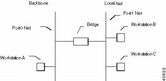
In Figure A-3, the bridge develops a table by listening to both the Port 0 net and the Port 1 net. Through the listening process, it associates Workstation A with Port 0 and Workstations B and C with Port 1. A simplified bridging table is shown below:
Figure A-3 Bridging Example
A -> Port 0
B -> Port 1
C -> Port 1
When a packet with A as a destination address arrives at Port 0, the packet is dropped (A is on the same interface). When a packet with a destination address of C arrives at Port 0, the packet is forwarded to Port 1. When a packet with a destination address which isn't in the table (or a broadcast address) arrives at Port 1, it is forwarded to Port 0.
Multiport Bridges/Switches and "Bridge Groups"
When a router has multiple interfaces, and also supports bridging/switching, some new concepts are required to understand the organization of the available functions.
Figure A-4 shows a four interface router which also supports bridging. Two of the router's interfaces (Port 0 and Port 1) are set to bridge IP, and two interfaces (Port 1 and Port 2) are also set to bridge IPX.
Figure A-4 Bridge Groups on a Multiport Router
The diagram illustrates two Bridge Groups. The IP Bridge Group consists of Port 0 and Port 1. The network segments connected to these two interfaces appear as a single logical segment for IP routing purposes. That is, they will share a single IP network number, subnet mask, and broadcast address. IP communications between these two segments will be bridged, not routed.
The IPX Bridge Group consists of Port 1 and Port 2. The network segments connected to these two interfaces appear as a single logical segment for IPX routing purposes. That is, they will share a single IPX network number. IPX communications between these two segments will be bridged, not routed.
In this example, the segment connected to Port 3 has its own IP network number, subnet mask, and broadcast address. It also has its own IPX network number. Thus all IP and IPX communications between this segment and the two Bridge Groups is routed.
Finally, assuming that non-routable protocols have not been excluded, Ports 0, 1 and 2 all appear as a single physical segment to NetBEUI and DEC LAT.
Frame Relay 101
Frame Relay is a streamlined subset of the X.25 packet switching protocol which has been used by many corporations for wide area communications for a number of years. By removing a number of the X.25 protocol's seldom-used functions and their associated overhead, the Frame Relay protocol allows communications at up to T1 speeds (about 1.5 megabits per second).
The generic advantage provided by Frame Relay is its ability to combine multiple streams of "bursty" data (such as LAN protocol traffic) all of which have relatively low average usage rates, into a single channel with a relatively higher average usage rate. This "statistical multiplexing" effect allows your Frame Relay carrier to provide high bandwidth wide area connectivity to you at a price which is often significantly lower than standard leased line rates.
Virtual Circuits
Like X.25, Frame Relay is a connection oriented service requiring circuits to be configured by your carrier to establish a physical link between two or more locations. Multiple virtual circuits (which appear as virtual point-to-point links) can be run through the same physical connection.
There are two types of virtual circuits supported in Frame Relay: Permanent Virtual Circuits (PVC) and Switched Virtual Circuits (SVC).
PVCs are like dedicated point-to-point private lines. Since the physical connection is always there in the form of a leased line, call setup and tear down is done by a carrier via a network management system.
SVCs are analogous to X.25 connections, which require call setup and tear down.
SVCs are generally not yet available from Frame Relay carriers. Virtually all Frame Relay communications is presently being done using PVCs.
Addressing
A number called the Data Link Connection Identifier (DLCI) identifies each virtual circuit within a shared physical channel.
Frame relay packets are exchanged between nodes by mapping packets containing the source node's DLCI address to the destination DLCI address at the switch. Each switch contains a table identifying the various DLCIs with their associated user lines and interface trunks. However, the switch has more or less work depending on if the DLCI has global or local significance.
Local & Global DLCIs
Local DLCI addressing means that DLCI numbers are only significant at one end of a Frame Relay virtual circuit (VC). In other words, the same VC will be identified by different DLCIs at each end. To accomplish this, a mapping occurs across a VC. Frame Relay switches are required to translate the "source" DLCI in a packet to the "destination" DLCI when forwarding the packet.
Global DLCI addressing is a Local Management Interface (LMI) extension that allows a DLCI number to have universal significance. A global DLCI identifies the same VC at both ends. Global addressing simplifies address administration but allows for only 1024 DLCIs in the entire network. The switch is not required to translate the DLCI in a packet as it does with local DLCIs.
The majority of Frame Relay connections use Local DLCI addressing, where a DLCI number is only significant at one end of the PVC.
Local Management Interface (LMI)
The local management interface specifies communication between different Frame Relay devices (i.e. frame relay switches, routers, access devices, etc.). Over the years, three different local management interface specifications have been developed for Frame Relay: "consortium" LMI (an early cooperative effort by a group of frame relay vendors), ITU-T Annex A, and ANSI Annex D. The ITU-T and ANSI specifications are formal outgrowths of the consortium LMI specification.
The Annex D specification is the most widely used in the United States, although consortium LMI is still in use by some carriers. The Annex A specification is primarily a European specification.
Encapsulation and Fragmentation
RFC 1490 describes an encapsulation method for carrying packets across a Frame Relay network. All protocol packets are encapsulated within a Q.922 Annex A frame (a ITU-T specification for data frames). Additionally, the frames must contain information necessary to identify the protocol being carried, allowing the receiver to properly process the incoming packet.
RFC 1490 also specifies a simple fragmentation procedure for carrying large frames over a frame relay network with a smaller maximum frame size.
Network/Protocol Addressing and Virtual Interfaces
Routing between LANs across a Frame Relay network is similar to routing across a point-to-point connection. A PVC on one router is directly connected to a PVC on another router. The difference is that multiple PVCs can be supported on the same physical interface of a router.
Network/protocol addresses are associated with each PVC using one of two methods: static mapping, or the Inverse Address Resolution Protocol (IARP).
IARP is outlined in RFC 1293. IARP allows dynamic mapping of protocol addresses to a DLCI. It can be used for IP, IPX and AppleTalk. It is more flexible and easier to configure than static configuration.
IARP is used when a router discovers a new PVC with its corresponding DLCI on a physical interface. The PVC is discovered by communicating with the Frame Relay switch using the LMI protocol. This may be done when the router is coming up or when a PVC has come back up after going down for some reason.
Frame Relay Example
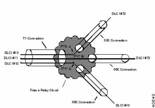
Figure A-5 shows three remote office 56K Frame Relay connections feeding one central office T1 connection. Note that the PVCs are shown as virtual point-to-point links which run through the physical connections and the Frame Relay cloud.
Figure A-5 A Frame Relay Example
The DLCI numbers in the diagram are only locally significant. That is, DLCI numbers can only be guaranteed to not be duplicated locally, and a DLCI at one location has no significance at another location.