Downloads |
 Feedback Feedback
|
Table Of Contents
Link Configuration: WAN Dialog Box
Dialing Retries / Connect Retries
Failover Timers Configuration Dialog Box
Frame Relay Configuration Dialog Box
Sequenced Predictor Compression
PPP Link Quality Configuration Dialog Box
Frequency in Seconds (Echo Packets)
LCP Options Configuration Dialog Box
WAN Chat Script Editor Dialog Box
Chat Script Editor Dialog Box Buttons & Controls
A Note About the AT Command Set
A Note About the V.25bis Command Set
User Authentication Database Dialog Box
WAN Link Protocols
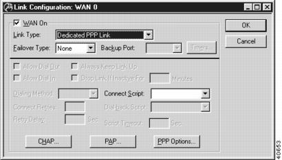
Link Configuration: WAN Dialog Box
To access this dialog box (Figure 10-1), select WAN/Link Configuration from the Device View.
Figure 10-1 Link Configuration: WAN Dialog Box
WAN On
This checkbox controls how wide area network traffic is handled for this interface.
•
If checked, then the interface will be active, link information can be configured with this dialog box, and network protocol configurations (TCP/IP Routing, IPX Routing, etc.) for the interface will take effect.
•
Link Type
This pull-down menu determines how the router will maintain the WAN link, and sets the low-level communications protocol which will be used on the line connected to this interface.
•
•
•
For On Demand PPP Link operation over EIA/TIA-232 DIN-8 interfaces, certain routers require that your communications device (modem, CSU/DSU, TA, etc.) be set to raise the DCD (data carrier detect) and/or DSR (data set ready) line when a connection is established, and drop it when the connection is terminated.
If an interface is set to On Demand PPP Link, there are certain maintenance packets for each protocol (IP, IPX, etc.) which will not cause an inactive connection to be dialed. This is a security measure that keeps intruders out and allows on-demand links to be useful.
The push buttons at the bottom of this dialog box will change depending on the choice you make for this pulldown.
Failover Type
WAN ports can be set to divert their traffic to a secondary port (known as "failing over") if a line problem is detected. This pull-down menu determines the failover mode for this port.
Ports set for PPP operation will fail over if the PPP echo protocol determines that the line is down. Ports set for Frame Relay operation will fail over if the router stops receiving Frame Relay switch maintenance packets, or if all user PVCs go down.
•
•
This pull-down menu will be disabled and will show "Backup" on a port which has been selected as a backup for a Primary port.
Backup Port
When the port has been set as a Primary failover port using the Failover Type pulldown menu, this pulldown allows a backup port to be set. If the line on the primary port goes down, traffic will be diverted to the designated backup port.
Once a port has been selected as a backup port for one primary it cannot be used as a backup for another.
This pull-down menu will be disabled, renamed to "Primary Port," and will show the Primary port's name on a port which has been selected to be a backup.
Timers
This button brings up the Failover Timers screen, which controls the amount of time before traffic is diverted from the Primary to a backup port when a Primary's line goes down, and the amount of time before traffic is diverted back to the Primary port when its line comes back up. The screen is described "Failover Timers Configuration Dialog Box" section.
Allow Dial Out
This checkbox tells the router whether traffic forwarded from other interfaces on this router will cause an on-demand connection to be established on this interface. This checkbox can only be set if the Link Type is On Demand PPP Link.
•
•
Allow Dial In
This checkbox tells the router whether it should accept incoming on-demand PPP connections from other routers (or end-node clients). This checkbox can only be set if the Link Type is On Demand PPP Link.
•
•
Always Keep Link Up
This checkbox tells the router whether it should always initiate a dialing sequence if there is no connection established for this interface. This checkbox can only be set if the Allow Dial Out checkbox is checked and the Drop Link If Inactive For checkbox is unchecked.
•
•
Drop Link If Inactive For
This checkbox and edit box tell the router how long it should wait once all traffic has been forwarded across the connection before dropping the link. If additional traffic is forwarded from another interface on the router before the link has been dropped, the timer will be reset.
•
•
There are certain maintenance packets for each protocol (IP, IPX, etc.) which will not cause the inactivity timer to be reset. This is a security measure that keeps intruders out and allows on-demand links to be useful.
Dialing Method
This pull-down menu lets you pick the dialing method which will be used for on-demand dialing on this interface. Which dialing method is used depends on the type of equipment being dialed. In general, asynchronous devices, such as modems, use AT style dialing. Synchronous devices, such as dialed CSU/DSU's and ISDN terminal adapters, generally use V.25bis style dialing.
•
•
Please check the manual for the communications device you are using to determine the best available dialing method for this interface.
Select routers support "chat scripts" which let you provide a sequence of commands (using chat "send" statements), and anticipated responses (using chat "expect" statements) to devices which need to be dialed.
Dial-Out / Connect Script
This pull-down menu selects the main chat script the router will run when attempting to initiate a connection.
You may choose any of the chat scripts which have been configured into the router. For more information on creating chat scripts, see the "WAN Chat Script Editor Dialog Box" section.
•
•
Dial-back Script
This pull-down menu provides a way to select a chat script which will provide global dial-back security on incoming connections to this interface. This option can only be used if you have checked both the Allow Dial Out and Allow Dial In boxes.
You may use this menu to choose any of the chat scripts which have been configured into the router. For more information on creating chat scripts, see the "WAN Chat Script Editor Dialog Box" section.
•
•
You may still enforce dial-back security on selected connections by correctly setting the parameters in the User Authentication Database dialog box discussed later in this chapter.
Dialing Retries / Connect Retries
Use this parameter to set the number of dialing retry attempts the router will make following an unsuccessful connection effort.
•
•
Values may range between 1 and 255.
Retry Delay Setting
This parameter sets the amount of time in seconds the router will wait between dialing attempts.
•
•
Values may range between 1 and 255.
Script Timeout
This is the amount of time in seconds the router will wait for input when it encounters an "Expect" statement in one of your chat scripts.
For more information on Expect statements and chat scripts in general, see the "WAN Chat Script Editor Dialog Box" section.
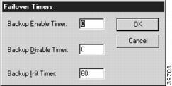
Failover Timers Configuration Dialog Box
You can access the Failover Timers Configuration dialog box (Figure 10-2) by selecting Primary in the Failover Type pulldown in the Link Configuration: WAN dialog box (under WAN/Link Configuration), and then selecting the Timers button.
Figure 10-2 Failover Timers Configuration Dialog Box
Backup Enable Timer
This is the number of seconds from the time the Primary port's line is detected as being down until traffic is diverted to the Backup port. This is also known as the "failover time."
Backup Disable Timer
This is the number of seconds from the time the Primary port's line is detected as having come back up until traffic is restored to the Primary port. This is also known as the "failback time" and is used to keep the router from switching out of failover mode too soon if the Primary link has an intermittent connection.
Backup Init Timer
This is the number of seconds after router startup before failover operation will go into effect. This timer allows PPP or Frame Relay communications time to stabilize before Primary port line status is checked.
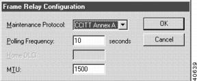
Frame Relay Configuration Dialog Box
You can access the Frame Relay Configuration dialog box (Figure 10-3) by selecting Frame Relay Link from the Link Type pulldown in the Link Configuration: WAN dialog box (under WAN/Link Configuration), and then clicking on the Frame Relay button at the bottom of the dialog box.
Figure 10-3 Frame Relay Configuration Dialog Box
Maintenance Protocol
This checkbox controls which Frame Relay maintenance protocol is used on this WAN interface. The maintenance protocol is used to send link status and virtual circuit information between Frame Relay switches and other devices (such as routers) that communicate with them.
•
•
•
•
Your Frame Relay carrier may or may not give you a choice of management protocols. If you are given a choice, we suggest Annex D since it is the most widely used.
Polling Frequency
The router is required to periodically poll the Frame Relay switch at the other end of the communications link in order to determine whether the link is active. This field determines how often the router polls the switch, using the Maintenance Protocol you have selected.
If any three out of four polls go unanswered by the switch, the router will assume the Frame Relay link is down. Every sixth poll, the router requests a full status packet from the switch in order to update its table of active permanent virtual circuits (PVCs).
This value is in seconds. The allowable range for the value is 5 to 30. The default is 10.
Home DLCI
When Static maintenance is used on a WAN broadcast medium, this edit box can be filled in to provide a statically assigned DLCI (Data Link Control Identifier) number for this interface.
This number can be configured into other routers' DLCI Mapping dialog boxes so that they can communicate with this router. In order to reject packets that were sent out its own interface, this router will ignore any packets with a sending DLCI number that matches this number.
MTU
This is the Maximum Transmission Unit in bytes for the interface. This setting may need to be adjusted in order to communicate with switches or routers from other vendors which do not support full size frame packets. The allowable range for the value is 262 to 1700. The default for this value is 1500.
Adjusting the MTU to a smaller size will cause fragmentation of Frame Relay packets, which will impact performance. This setting should be left at the default unless it must be changed for compatibility reasons.
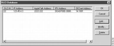
DLCI Database Dialog Box
You can access the Frame Relay DLCI Database dialog box (Figure 10-4) by selecting Frame Relay Link from the Link Type pulldown in the Link Configuration: WAN dialog box (under WAN/Link Configuration), and then clicking on the DLCI button at the bottom of the dialog box. This window displays all DLCI mapping entries, but is not used to add or modify the entries.
Figure 10-4 DLCI Database Configuration Dialog Box
To add or modify the entries, you must access the DLCI Entry dialog box by selecting the Add... or Modify... buttons in the Frame Relay DLCI Database dialog box (Figure 10-5).
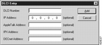
Figure 10-5 DLCI Entry Dialog Box
The Data Link Connection Identifier (DLCI) is a number which uniquely identifies one end of a Permanent Virtual Circuit (PVC) to your Frame Relay carrier's Frame Relay switch. The DLCIs are not interchangeable between the two ends of a PVC, since they only identify one end of the PVC. Unless you use the correct DLCI numbers at each end of your PVC, two-way communications cannot take place.
This database lets you create static mappings between the Frame Relay PVCs on this interface (identified by their DLCI number) and the protocol (e.g. IP, IPX, etc.) addresses of the router interfaces at the far ends of the PVCs.
If the router at the far end of a PVC is a Compatible Systems router, you will generally not need any entries in the DLCI database for it. Compatible Systems routers use the IARP (Inverse Address Resolution Protocol) to dynamically create the same type of mappings that are manually entered in the DLCI database.
A router will not use IARP to attempt to discover addresses for a particular protocol on a PVC if there is already a DLCI database entry for the PVC for that protocol. Therefore, if you wish to use IARP to dynamically discover the addresses at the far end of a PVC, do not make any entries for its DLCI number in the DLCI database.
Frame Relay DLCIs must be statically mapped using the DLCI mapping database when IP subinterfaces are in use, because IARP can only resolve a physical port, not a logical subinterface on that port.
DLCI #
This is the decimal number between 16 and 991 which uniquely identifies this end of a PVC. A DLCI number will be provided to you by your Frame Relay carrier for each end of each PVC.
IP Address
This is the IP address of the router interface at the other end of the PVC. It should be entered in standard IP dotted-decimal notation (e.g. 198.041.9.1).
AppleTalk Address
This is the AppleTalk address of the interface of the router WAN interface at the other end of the PVC. It should be entered in decimal as a "network:node" pair (e.g. 24:1).
The AppleTalk network number must be between 1 and 65,279. The node address must be between 1 and 254.
IPX Address
This is the IPX address of the interface of the router WAN interface at the other end of the PVC. It should be entered in hexadecimal as a "network:node" pair (e.g. 12F0A:00A510123456).
The IPX network number must be between 1 and FFFFFFFE. The IPX node address must be 12 hexadecimal digits.
The IPX node address at the other end is generally a "borrowed" Ethernet address from one of the other router's Ethernet interfaces. There is no addressing conflict because the actual Ethernet interface is on a network with a different IPX network number.
DECnet Address
This is the DECnet address of the router at the other end of the PVC. The address consists of a decimal "area.node" pair (e.g. 14.1001).
The area value must be within the range of 1 to 63. The node value must be within the range of 1 to 1023.
A period is traditionally used as the separator for DECnet area:node pairs. Other protocols use a colon.
CHAP Configuration Dialog Box
You can access the CHAP (Challenge Handshake Authentication Protocol) Configuration dialog box (Figure 10-6) by selecting On Demand PPP Link or Dedicated PPP Link from the Link Type pulldown in the Link Configuration: WAN dialog box (under WAN/Link Configuration), and then clicking on the CHAP button at the bottom of the dialog box.
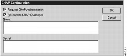
Figure 10-6 CHAP Configuration Dialog Box
CHAP is a security protocol that allows devices using PPP to authenticate their identities to each other through the use of a message digest (MD5) calculation. Either or both ends of a link can request that the opposite end of the link authenticate itself. CHAP requests do not depend on knowing which device initiated a call, so a calling device can request and/or provide authentication, as can a device that receives a call.
CHAP authentications can be performed at any time after a communications link is connected. A CHAP authentication sequence begins with a "challenge" from one end of the link. The challenge includes the name of the challenging router.
The response to the challenge includes the name of the responding router. This name will be looked up in the challenging router's database or on a configured RADIUS server. The name, along with a "secret" value that is stored in the database or RADIUS server and is shared by both ends, will be processed by the challenging end using the MD5 algorithm.
If the result of an identical MD5 calculation performed by the challenging end is not the same, the challenging end drops the link.
To access the User Authentication Database Configuration dialog box, select Global/User Authentication Database in the Device View. To access the RADIUS Configuration dialog box, select Global/System Configuration in the Device View and click on the RADIUS button.
Because the secret is never passed across the link, even in encrypted form, CHAP is considered to be significantly more secure than PAP.
Request CHAP Authentication
This checkbox controls whether this router will send a CHAP challenge to the other end before allowing PPP negotiation to complete. Each challenge will include this router's Name, along with a random value selected by this router.
•
•
Respond to CHAP Challenges
This checkbox controls whether this router will respond to CHAP challenges from the other end.
•
•
Name
This is the name that the router will include in any CHAP challenges it makes, and in any CHAP responses it provides. A name is required if either Request CHAP Authentication or Respond to CHAP Challenges is checked. The name can be from 1 to 255 characters in length.
Secret
This is the shared information that is used to calculate expected CHAP responses to challenges issued by this router. A secret is required if Respond to CHAP Challenges is checked. The secret can be from 1 to 255 characters in length.
CHAP functionality was changed in version 3.04 and higher of Compatible Systems' router software in order to allow for effective use of RADIUS servers. CHAP in versions 3.04 and later are not downward compatible with earlier versions.
PAP Configuration Dialog Box
You can access the PAP (Password Authentication Protocol) Configuration dialog box (Figure 10-7) by selecting On Demand PPP Link or Dedicated PPP Link from the Link Type pulldown in the Link Configuration: WAN dialog box (under WAN/Link Configuration), and then clicking on the PAP button at the bottom of the dialog box.
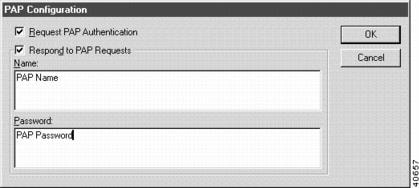
Figure 10-7 PAP Configuration Dialog Box
PAP is a security protocol that allows devices using PPP to authenticate their identities to each other through the use of passwords. Either or both ends of a link can request that the opposite end of the link authenticate itself. PAP requests do not depend on knowing which device initiated a call, so a calling device can request and/or provide authentication, as can a device that receives a call.
PAP authentications are only performed after a communications link is connected, but before PPP has completely negotiated the communications parameters which will be used on the link. A PAP authentication sequence begins with a "PAP request" from one end of the link. The other end must respond with a valid name and password. If it does not, the requesting end drops the link.
Because PAP passes the name and password values back across the link in "cleartext," it is considered to be less secure than CHAP.
Request PAP Authentication
This checkbox controls whether this router will request a PAP name and password from the other end before allowing PPP negotiation to complete.
All name/password combinations received are checked against the entries in the User Authentication Database, or in a configured RADIUS server.
To access the User Authentication Database Configuration dialog box, select Global/User Authentication Database in the Device View. To access the RADIUS Configuration dialog box, select Global/System Configuration in the Device View and click on the RADIUS button.
•
•
Respond to PAP Requests
This checkbox controls whether this router will supply a PAP name and password to the other end if they are requested.
•
•
Name
This is the name that the router will provide to the device at the other end if PAP name/password information is requested and the Provide PAP Information checkbox is checked. The name can be from 1 to 255 characters in length.
Password
This is the password that the router will provide to the device at the other end if PAP name/password information is requested and the Provide PAP Information checkbox is checked. The password can be from 1 to 255 characters in length.
SMDS Dialog Box
You can access the SMDS dialog box (Figure 10-8) by selecting SMDS from the Link Type pull-down in the Link Configuration: WAN dialog box (under WAN/Link Configuration), and then clicking on the SMDS button at the bottom of the dialog box.
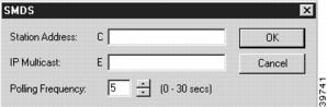
Figure 10-8 SMDS Dialog Box
Station Address
This is the SMDS physical station address. The address is assigned by the service provider and follows the E.164 format (i.e., 64-bit/15-digit addressing). The station address must start with the letter C and be followed by at least 10 digits.The missing digits will be filled in with F. The address should be entered exactly as it is assigned by the service provider.
IP Multicast
This is the IP multicast address. This address is the SMDS group address assigned by the service provider and follows the E.164 format. The multicast address must start with the letter E and be followed by at least 10 digits. The missing digits will be filled in with F. The address should be entered exactly as it is assigned by the service provider.
Polling Frequency
This number specifies the interval that the router uses to poll the SMDS switch. The interval is specified in seconds and must be between 0 and 30.
If the switch does not respond to the polling, the router will eventually declare the SMDS link down and start dropping packets designated for that interface. A value of 0 will disable the polling mechanism. Disabling the polling mechanism will automatically declare the SMDS link up.
The keepalive mechanism is also referred to as "heartbeat exchange" in SMDS literature.
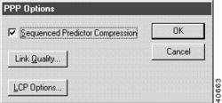
PPP Options Dialog Box
You can access the PPP Options dialog box (Figure 10-9) by selecting On Demand PPP Link or Dedicated PPP Link from the Link Type pulldown in the Link Configuration: WAN dialog box (under WAN/Link Configuration), and then clicking on the PPP Options button at the bottom of the dialog box.
Figure 10-9 PPP Options Dialog Box
Sequenced Predictor Compression
Packet data can be compressed to provide better throughput across slower WAN links. Sequenced Predictor is a compression algorithm used in some Compatible Systems routers.
•
A general rule of thumb for Compatible Systems routers would be to use Sequenced Predictor on uncompressed links at up to 128K rates, but to turn it off at higher speeds or if other means of compression (such as the V.42 compression built into modems) are in use. A few simple file copy transfer tests over your particular WAN setup will yield a more exact answer.
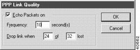
PPP Link Quality Configuration Dialog Box
You can access the PPP Link Quality Configuration dialog box (Figure 10-10) by selecting On Demand PPP Link or Dedicated PPP Link from the Link Type pulldown in the Link Configuration: WAN dialog box (under WAN/Link Configuration), and then clicking on the PPP Options button at the bottom of the dialog box, and then clicking on the Link Quality button at the bottom of the PPP Options dialog box.
Figure 10-10 PPP Link Quality Configuration Dialog Box
This dialog box is used to set parameters which allow a router using PPP to monitor the quality of an on-demand WAN link. If poor link quality is detected, the line can be dropped and redialed to improve performance.
Echo Packets On
This checkbox controls whether this router will use an echo protocol to monitor the quality of the line.
The number of echo packets sent, and the number of responses, are counted. If the conditions set in the Drop Link When... fields are met, the link is dropped.
If checked, echo packets will be regularly sent, and line quality monitored.
Frequency in Seconds (Echo Packets)
This parameter determines how often an echo packet will be sent to the other end. The value must be in the range of 1 to 32.
Drop Link When
These parameters set the size of the echo sequence that will be tracked, and the number of packets that must be lost out of a sequence before the link will be dropped. The values must be in the range of 1 to 32.
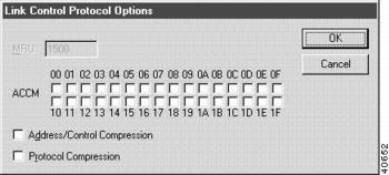
LCP Options Configuration Dialog Box
You can access the LCP Options Configuration dialog box (Figure 10-11) by selecting On Demand PPP Link or Dedicated PPP Link from the Link Type pulldown in the Link Configuration: WAN dialog box (under WAN/Link Configuration), and then clicking on the PPP Options button at the bottom of the dialog box, and then clicking on the LCP Options button at the bottom of the PPP Options dialog box.
Figure 10-11 LCP Options Configuration Dialog Box
This dialog box is used to set parameters relating to PPP's internal operation. You will probably never need to change the settings in this dialog box.
MRU
This is the Maximum Receive Unit size in bytes for PPP packets. The default value is 1500 bytes.
ACCM
The Asynchronous Character Control Map allows you to set characters which must be "escaped" for your particular communications link. For the vast majority of communications links, the default (no characters escaped) is correct.
If you set Flow Control to XOn/XOff in the Interface Configuration dialog box (under WAN/Physical Configuration) for this WAN interface, the characters for XOn and XOff will automatically be escaped by the router.
Address/Control Compression
This checkbox controls whether this router will use the method defined in the PPP specification for compression of the PPP address and control fields. The default is checked.
Protocol Compression
This checkbox controls whether this router will use the method defined in the PPP specification for compression of the PPP protocol fields. The default is checked.
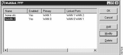
Multilink PPP Dialog Box
This dialog box (Figure 10-12) is used to configure Multilink PPP (MPPP) parameters for multiple WAN interfaces. MPPP allows multiple physical links to be combined into a "bundle" which provides a virtual link with greater bandwidth than a single link
To access this dialog box, select Global/Multilink PPP from the Device View. This dialog box defines a list of MPPP bundles and the physical WAN ports that are included in each bundle.
Figure 10-12 Multilink PPP Dialog Box
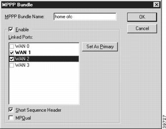
To add or modify this list, click on the appropriate button to open the MPPP Bundle dialog box (Figure 10-13).
Figure 10-13 MPPP Bundle Dialog Box
MPPP Bundle Name
This edit box allows you to specify a name for the multilink virtual port.
Enable
This checkbox is used to specify whether multilink bundling will function on this router.
Linked Ports
Check each of the physical WAN ports that you wish to include in the bundle. You must select at least two ports.
Set as Primary
Select which interface in the bundle should be used by the router to configure the network protocol for the multilink, and click on the Set as Primary button.
Short Sequence Header
This checkbox allows the router to use an abbreviated sequence number in its multilink headers.
While the shorter header can enhance performance slightly, routers from other vendors may not be compatible with this feature.
MPQual
This checkbox allows the router to use echo packets on each of the physical ports in the bundle to determine whether individual links are up. If one link in a bundle goes down, the router can divert data away from that port.
If the primary port goes down, the entire link will go down, even if MPQual is enabled. If left unchecked, any individual link in the bundle can bring down the entire multilink. (Parameters for echo packets are configured in the PPP Options/PPP Link Quality dialog box, see"PPP Options Dialog Box" section.)
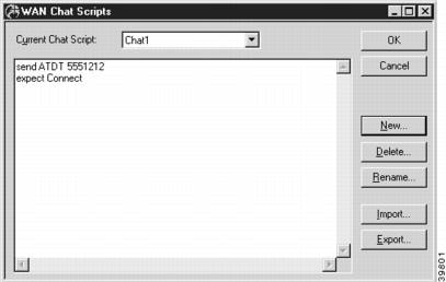
WAN Chat Script Editor Dialog Box
You can access the Chat Script Editor dialog box (Figure 10-14) by selecting Global/WAN Chat Scripts in the Device View.
Figure 10-14 WAN Chat Script Editor Dialog Box
Compatible Systems Legacy routers support standard communications chat scripts that let you specify dialing and/or connect sequences between this router and remote routers or terminal servers.
All of the chat scripts stored in a router are available to any of the router's WAN interfaces. To select the scripts which will be used on a specific interface, use the Dial-out Script / Connect Script and Dial-back Script pull-down menus in the VPN 5000 Manager's Link Configuration: WAN dialog box. You can access this dialog box by selecting WAN/Link Configuration from the Device View.
These scripts may also be used for user-specific dial-back scripts in the User Authentication dialog box, and can be selected from there. Access this dialog box by selecting Global/User Authentication Database in the Device View.
Chat Script Editor Dialog Box Buttons & Controls
•
•
•
•
•
•
Chat Script Rules and Syntax
Every line in a chat script must start with either send or expect in order to be a valid chat script line.
•
•
The amount of time the router will wait is determined by the Script Timeout parameter in the Link Configuration: WAN dialog box.
All control characters are preceded by a backslash character (\) which tells the router that what follows is an escaped character and should not be literally sent on the WAN interface.
•
•
•
•
•
•
•
•
•
•
A Note About the AT Command Set
Most asynchronous devices (e.g. modems and some terminal adapters) expect AT commands from the router in order to dial or perform other functions. Different modems support different subsets of AT commands. To be certain that the AT commands you are using are correct for your modem, you must refer to the manual that came with your modem.
Every AT command is preceded by "AT," which tells the modem that the string is destined for it. Listed are the most common (and commonly supported) AT commands:
•
An asynchronous terminal adapter does not use tones to dial ISDN phone numbers. Use ATD to dial ISDN phone numbers.
•
•
•
Modems typically provide a response message depending on the success of an attempted call:
•
Compatible Systems routers automatically send standard modem setup parameters when a port's Dialing Method is set for AT dialing. These setup parameters are adequate for virtually all dial-up applications. In almost all cases, your modem should work right out of the box.
A Note About the V.25bis Command Set
Different CSU/DSU's and Terminal Adapters support different subsets of the V.25bis commands. To be certain that the V.25bis commands you are using are correct for your communications device, you should refer to the manual that came with the device.
The V.25bis commands use hardware signaling to denote whether the information they are sending is destined for the communications device or the data link itself. Listed are the most common (and commonly supported) V.25bis commands:
•
To include a pound sign (#) as part of the number sequence, it must be enclosed in double quotes ("").
•
Communications devices provide several responses depending on the outcome of an attempted call:
•
•
•
•
•
If your router is connected to a device synchronously, make sure to configure it to accept V.25bis commands in bit-synchronous format (i.e. within HDLC packets). This is the format Compatible Systems routers use to send V.25bis commands.
Chat Script Examples
There are as many variations of chat scripts as there are specific installation requirements. However, all chat scripts generally follow the same format, which is a series of send and expect statements.
•
send atdt 9,13035559000
expect CONNECT
•
send CRN 5554000
expect CNX
•
send atdt 5551000
expect CONNECT
expect login:
send myname
expect ssword:
send im4CSCru2
expect connecting
As demonstrated in this script, it may be convenient to only put part of the expected response in an expect statement. This can make it easier to get an exact match when the actual expected string is long (e.g. Please login:, Please enter your password:, etc.).
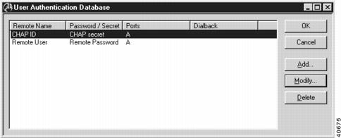
User Authentication Database Dialog Box
You can access the User Authentication Database Configuration dialog box (Figure 10-15) by selecting Global/User Authentication Database in the Device View. This dialog box displays all database entries, but is not used to add or modify the entries.
Figure 10-15 User Authentication Database Configuration Dialog Box
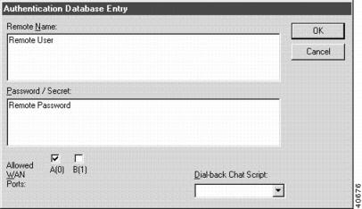
To add or modify database entries, you must access the Authentication Database Entry dialog box by selecting the Add... or Modify... buttons in the User Authentication Database Configuration dialog box (Figure 10-16).
Figure 10-16 Authentication Database Entry Dialog Box
This database is global to the router. If you have configured a RADIUS server, entries in this database will take precedence over RADIUS entries.
Remote Name
This is the name of the remote device.
•
•
If there is a Compatible Systems router at the far end, these names correspond to the names entered in the CHAP Configuration dialog box and/or PAP Configuration dialog box Name fields.
Password/Secret
This is the password or secret string for the remote device.
•
•
If there is a Compatible Systems router at the far end, these strings correspond to the Password entered in the PAP Configuration dialog box and/or the Secret entered in the CHAP Configuration dialog box.
Interfaces
This is the list of interfaces on which we will accept the entered Name and Password as valid. The entry will be invalid on interfaces not selected here.
Dial-back Chat
If a chat script is selected in this pulldown, then upon successful negotiation of PAP or CHAP, the link will be dropped and the selected chat script will be executed.