Feedback
Table Of Contents
Installing Interface Cables to the PIX 520
Removing and Replacing the PIX 520 Chassis Cover
Installing a Circuit Board in the PIX 520
Gigabit Ethernet Circuit Board
Installing the PIX 520 DC Model
PIX 520
This chapter guides you through the installation of the PIX 520, and includes the following sections:
•
Installing LAN-Based Failover
•
•
•
Note
PIX 520 Product Overview
This section describes the PIX 520 front and rear panels and the panel LEDs.
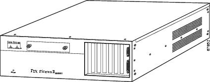
Figure 5-1 shows the front view of the PIX 520.
Figure 5-1 PIX 520 Front Panel
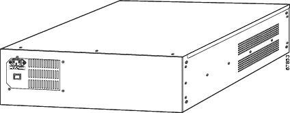
Figure 5-2 shows the rear view of the PIX 520.
Figure 5-2 PIX 520 Rear Panel
Note
The PIX 520 can be used with Ethernet circuit boards.
The four-port Ethernet circuit board provides four 10/100 Ethernet connections and has autosense capability. Connectors on the four-port Ethernet circuit board are numbered top to bottom sequentially; however, the actual device number depends on the slot in which the four-port Ethernet circuit board is installed.
Table 5-1 describes how the top connector is numbered.
With the four-port Ethernet circuit board, having a circuit board in slot 3 makes the number of interfaces greater than six; while the circuit board in slot 3 cannot be accessed, its presence does not cause problems with the PIX security appliance.
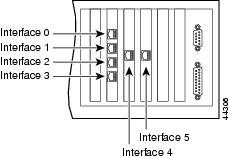
Figure 5-3 shows the location of the interfaces if you install a four-port Ethernet circuit board in slot 0.
Figure 5-3 Four-Port Ethernet Circuit Board Installed in Slot 0
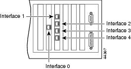
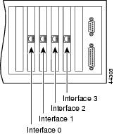
Figure 5-4 shows how the slots are numbered if a single-port Ethernet circuit board is inserted in
slot 0, and a four-port Ethernet circuit board is inserted in slot 1.Figure 5-4 Single-Port Ethernet Circuit Board Installed in Slot 0 and Four-Port Ethernet Circuit Board Installed in Slot 1
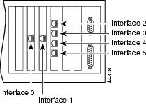
Figure 5-5 shows how the slots are numbered if single-port Ethernet circuit boards are installed in slot 0 and in slot 1, and a four-port Ethernet circuit board is inserted in slot 2.
Figure 5-5 Single-Port Ethernet Circuit Board Installed in Slot 0 and 1 and Four-Port Ethernet Circuit Board Installed in Slot 2
Installing the PIX 520
To install the PIX 520, perform the following steps:
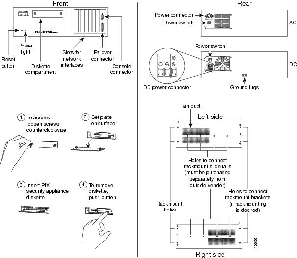
Step 1
Figure 5-6 PIX 520 Front, Rear, and Side Panels
Step 2
If you are not installing a four-port Ethernet circuit board, add the cables as shown in Figure 5-7.
Figure 5-7 Up to Four Single-Port Interfaces in the PIX Security Appliance
Installing Interface Cables to the PIX 520
To install interface cables to the PIX 520, perform the following steps:
Step 1
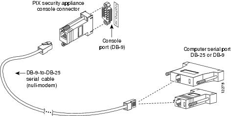
Step 2
Figure 5-8 PIX Security Appliance Serial Cable Assembly
Step 3
Step 4
Step 5
If you are installing a DC voltage PIX security appliance, refer to the "Installing the PIX 520 DC Model" section.
Step 6
a.
Note
•
http://www.cisco.com/en/US/products/sw/secursw/ps2120/prod_command_reference_list.html
b.
c.
If you are ready to start configuring the PIX security appliance, power on the unit. Refer to the configuration guide online at:
http://www.cisco.com/en/US/docs/security/asa/asa70/configuration/guide/config.html
Always check the release notes first before configuring the PIX security appliance for the latest release details. You can find the latest versions of release notes online at:
http://www.cisco.com/en/US/products/sw/secursw/ps2120/prod_release_notes_list.html
PIX 520 Feature Licenses
If you have a PIX 520-UR unrestricted feature license, the following options are available:
•
•
http://cisco.com/en/US/products/sw/secursw/ps2120/prod_command_reference_list.html
•
Note
•
Installing Failover
To install a failover connection, perform the following steps:
Note
Step 1
Note
Step 2
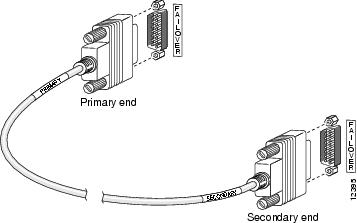
Figure 5-9 PIX 520 Failover Cable Connection
Step 3
Step 4
Step 5
Step 6
•
•
•
•
http://cisco.com/en/US/products/sw/secursw/ps2120/prod_command_reference_list.html.
Caution
Step 7
Within a few seconds, the active unit automatically downloads its configuration to the standby unit.
If the primary unit fails, the secondary unit automatically becomes active.
Installing LAN-Based Failover
LAN-based failover supports failover between two units connected over a dedicated Ethernet interface. LAN-based failover eliminates the need for a special Failover cable and overcomes the distance limitations imposed by the Failover cable.
For information on configuring a LAN-based failover, refer to the configuration guide online at:
http://www.cisco.com/en/US/docs/security/asa/asa70/configuration/guide/config.html
Note
To set up a LAN-based failover connection, perform the following steps:
Step 1
Step 2
http://www.cisco.com/en/US/docs/security/asa/asa70/configuration/guide/config.html
Step 3
Step 4
Note
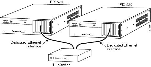
Figure 5-10 LAN-Based Failover Connections
Step 5
•
•
•
Note
Caution
Step 6
If the primary unit fails, the secondary unit automatically becomes active.
Removing and Replacing the PIX 520 Chassis Cover
This section describes how to remove and replace the chassis cover from the PIX 520. This section includes the following topics:
Removing the Chassis Cover
To remove the chassis cover, perform the following steps:
Note
Step 1
Step 2
Warning
Step 3
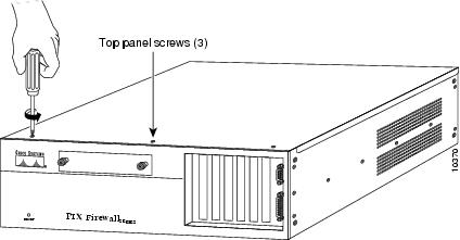
Figure 5-11 Removing the Chassis Cover Screws
Step 4
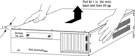
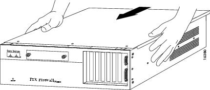
Figure 5-12 Removing the Chassis Cover
Replacing the Chassis Cover
Caution
To replace the chassis cover, perform the following steps:
Step 1
Step 2
Step 3
Figure 5-13 Replacing the Chassis Cover
Replacing a Lithium Battery
The PIX security appliance has a lithium battery on its main circuit board. This battery has an operating life of about ten years. When the battery loses its charge, the PIX security appliance cannot function. The lithium battery is not a field-replacable unit (FRU). Contact Cisco TAC to replace the battery.
Note
Warning
Installing a Memory Upgrade
Observe the following warnings, cautions, and notes when installing additional PIX security appliance system memory.
The following statement applies to DC models:
Warning
The following statement applies to both AC and DC models:
Warning
Caution
Note
Caution
Memory Installation Steps
To install additional system memory, perform the following steps:
Step 1
Step 2
Remove the chassis cover from the PIX security appliance. Remove all screws holding the assembly in place. Refer to the "Removing and Replacing the PIX 520 Chassis Cover" section for more information.
Step 3
Step 4
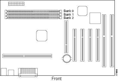
Figure 5-14 PIX 520 System Memory Location
Step 5
Step 6
Step 7
•
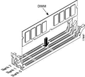
•
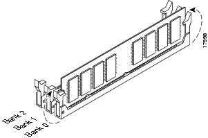
Figure 5-15 Inserting a DIMM Memory Strip in the PIX 520
Figure 5-16 Securing a DIMM Memory Strip in the PIX 520
•
http://cisco.com/en/US/products/sw/secursw/ps2120/prod_command_reference_list.html.
Installing a Circuit Board in the PIX 520
The information in this section refers to the installation of a circuit board in the PIX 520.
The 4-port 64 bit/66 MHz FE card (PIX-4FE-66) is supported in software Versions 6.3, 6.2(2), 6.1(4), and 5.2(9), and later versions. These are the minimum software versions that support the card.
Note
The new card has the following characteristics:
•
•
•
•
This section includes the following topics:
•
•
•
To install a circuit board in the PIX 520, perform the following steps:
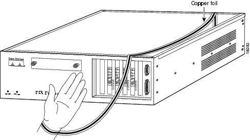
Step 1
Figure 5-17 Attaching Grounding Strap to Your Wrist and to the PIX Security Appliance
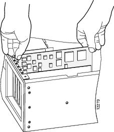
Step 2
Figure 5-18 Installing the New Circuit Board
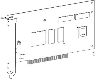
Step 3
Note
Figure 5-19 PIX Security Appliance Network Circuit Boards
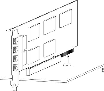
Step 4
Figure 5-20 4-Port Circuit Board Overlap
16 MB Flash Circuit Board
Along with upgrading your Flash memory to 16 MB, the PIX security appliance 16 MB Flash circuit board includes pre-installed PIX security appliance software and a UR (unrestricted) 56-bit DES encryption license. The 16 MB Flash circuit board installs into the PIX security appliance ISA slot.
An illustration of the 16 MB Flash circuit board is shown in Figure 5-21.
Figure 5-21 PIX Security Appliance 16 MB Flash Circuit Board
Use the following information to install a 16 MB Flash circuit board:
•
•
•
•
To install the 16 MB Flash circuit board, perform the following steps:
Step 1
Step 2
Note
Step 3
Step 4
Step 5
Caution
Step 6
VPN Accelerator Circuit Board
The VPN Accelerator (PIX-VPN-ACCEL) is an encryption and accelerator circuit board. The VPN Accelerator uses a PCI interface and therefore can only be installed in PIX security appliance platforms with PCI slots. The VPN Accelerator begins to function immediately after installation without the need of special installation configurations.
Note
An illustration of the VPN Accelerator is shown in Figure 5-22.
Figure 5-22 VPN Accelerator Circuit Board
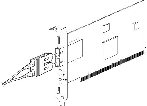
Gigabit Ethernet Circuit Board
PIX security appliance supports 1000 Mbps (Gigabit) Ethernet. The Gigabit Ethernet circuit board uses only has one hardware speed and the following duplex options:
•
•
•
The Gigabit Ethernet circuit board and the fiber optic cable connection are shown in Figure 5-23.
Figure 5-23 Gigabit Ethernet Circuit Board
The Gigabit Ethernet circuit board has three LEDs:
•
•
•
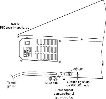
Installing the PIX 520 DC Model
Warning
To install the PIX 520 DC power model, perform the following steps:
Step 1
Step 2
Step 3
Step 4
Figure 5-24 Attaching a Grounding Lug to the PIX Security Appliance
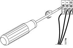
Step 5
Step 6
Step 7
Figure 5-25 Attaching DC Power Cables
Step 8
Step 9
Step 10
Step 11
Note