Installing a Circuit Board

Table Of Contents

Installing a Circuit Board

PIX Firewall Circuit Board Options

Safety Information

Installing a Circuit Board in a PIX 535

Circuit Board Slot Description

Installing the Circuit Board

Network Interface LEDs

Installing a Circuit Board in a PIX 525

Installing a Circuit Board in a PIX 515

Installing a Circuit Board in a PIX 520 and Earlier Model

PIX Firewall 16 MB Flash Circuit Board

PIX Firewall 16 MB Flash Installation

PIX Firewall VPN Accelerator Circuit Board

Gigabit Ethernet Circuit Board

FDDI Circuit Board


Installing a Circuit Board


Before using this chapter, refer to "Opening a PIX Firewall Chassis," for instructions on how to open the chassis for each model of PIX Firewall. You can use the information in this chapter to install optional circuit boards.

The information in this chapter does not apply to the PIX 506.

This chapter includes the following sections:

PIX Firewall Circuit Board Options

Safety Information

Installing a Circuit Board in a PIX 535

Installing a Circuit Board in a PIX 525

Installing a Circuit Board in a PIX 515

Installing a Circuit Board in a PIX 520 and Earlier Model

PIX Firewall 16 MB Flash Circuit Board

PIX Firewall VPN Accelerator Circuit Board

Gigabit Ethernet Circuit Board

FDDI Circuit Board

PIX Firewall Circuit Board Options

Table 7-1 and Table 7-2 list the optional circuit board combinations that are available for the PIX 525 and PIX 535. The maximum number of slots for the circuit boards varies for each model of the PIX Firewall.

Table 7-1 PIX 535 Interface Options

Restricted
Unrestricted

6 GE

8 GE

5 GE + 1 FE

7 GE + 1 FE

4 GE + 2 FE

6 GE + 2 FE

3 GE + 1 VPN Accelerator + 2 FE

5 GE + 3 FE

3 GE + 3 FE

4 GE + 4 FE

2 GE + 1 VPN Accelerator + 3 FE

3 GE + 5 FE

2 GE + 4 FE

3 GE + 1  4-port FE + 1 FE

2 GE + 1  4-port FE

3 GE + 1 VPN Accelerator + 4 FE

1 GE + 1 VPN Accelerator + 1  4-port FE

3 GE cards + 1 VPN Accelerator + 1  4-port FE

1 GE + 1 FE card + 1  4-port FE

2 GE cards + 1 VPN Accelerator + 5 FE

6 FE

2 GE cards + 1 VPN Accelerator + 1  4-port FE + 1 FE

2 FE + 1  4-port FE

1 GE card + 1 VPN Accelerator + 1  4-port FE + 2 FE


1 GE card + 1 VPN Accelerator + 6 FE


8 FE


2  4-port FE


1  4-port FE card + 4FE


Table 7-2 PIX 525 Interface Options 

Restricted Interface Options
Unrestricted Interface Options

3 FE

3 FE

2 FE + 1 VPN Accelerator

2 FE + 1 VPN Accelerator

3 GE

3 GE

2 GE + 1 VPN Accelerator

2 GE + 1 VPN Accelerator

1 4-Port FE

1 4-port FE

1 4-Port FE + 1 VPN Accelerator

1 4-port FE + 2 FE


1 4-port FE + 2 GE


1 4-port FE + 1 VPN Accelerator


1 4-port FE + 1 VPN Accelerator + FE


1 4-port FE + 1 VPN Accelerator + GE


Safety Information

The following statement applies to DC models:


Warning Before performing any of the following procedures, ensure that power is removed from the DC circuit. To ensure that all power is OFF, locate the circuit breaker on the panel board that services the DC circuit, switch the circuit breaker to the OFF position, and tape the switch handle of the circuit breaker in the OFF position.


The following statement applies to both AC and DC models:


Warning Before working on a system that has an On/Off switch, turn OFF the power and unplug the power cord.


Installing a Circuit Board in a PIX 535

The information in this section refers to all models of the PIX 535.

The following sections are included in this chapter:

Circuit Board Slot Description

Installing the Circuit Board

Network Interface LEDs

Circuit Board Slot Description

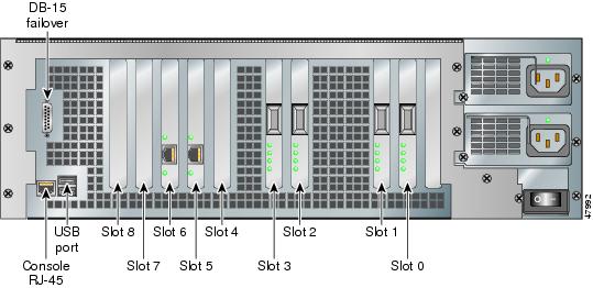
There are eight circuit board slots (see Figure 7-1) using three separate buses for the PIX 535.

Figure 7-1 PIX 535 Back Panel Detail

The slots and buses are configured as follows:

Slots 0 and 1—64-bit/66 MHz Bus 0

Slots 2 and 3—64-bit/66 MHz Bus 1

Slots 4 to 8—32-bit/33 MHz Bus 2

For optimum performance and throughput for the interface circuit boards, you must use the following guidelines:

A total of six interface circuit boards are configurable with the restricted license and a total of eight are configurable with the unrestricted license.

PIX-1GE-66 (66 MHz) circuit boards can be installed in any slot, but should be installed in the 64-bit/66 MHz Bus first. Up to eight PIX-1 GE-66 circuit boards can be installed.

The FE circuit board (33 MHz) can be installed in any bus or slot (32-bit/33 MHz or
64-bit/66 MHz). Up to eight single-port FE circuit boards or up to two four-port FE circuit boards can be installed.

The four-port FE circuit board should only be installed in the 32-bit/33 MHz Bus.

Do not mix the 33 MHz circuit boards with the 66 MHz GE circuit boards on the same
64-bit/66 MHz bus (Bus 0 or Bus 1). The overall speed of the bus will be reduced by the lower speed circuit board.

The VPN Accelerator should only be installed in the 32-bit/33 MHz Bus.

Installing the Circuit Board


Note It is not necessary to remove the top panel on the PIX 535 to install or replace a circuit board. A component tray, that slides out from the rear panel, contains slots for installing circuit boards and memory boards.


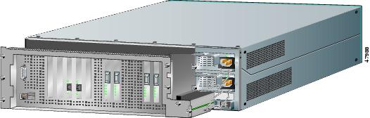
With Figure 7-2 as a guide, use the following steps to install a circuit board in the PIX 535:


Step 1 Locate the grounding strap from the accessory kit. Fasten the grounding strap to your wrist so that it contacts your bare skin. Attach the other end to bare metal on the PIX 535 chassis.

Figure 7-2 The Component Tray at the Back of the PIX 535

Step 2 Loosen the attachment screws from the rear panel of the component tray and slide the tray out.

Step 3 Select a slot for the circuit board and remove the screw and slot cover plate from the back panel on the component tray.

Step 4 Install the circuit board into the slot. The front plate on the circuit board should be against the slot opening on the component tray back panel.

Step 5 Use the screw that was removed in Step 3 to attach the circuit board front plate to the component tray rear panel.

Step 6 Reinstall the component tray and tighten the attachment screws.


Network Interface LEDs

Depending upon the type of interface, there are four possible LEDs for the each port on a network interface circuit board. The LEDs for the network interface ports display the following transmission states:

100 Mbps—100 megabits per second 100BaseTX communication. If the light is off during network activity, that port is using 10 megabits per second data exchange.

ACT—Shows network activity.

LINK—Shows that data is passing through that interface.

FDX—Shows that the connection uses full-duplex data exchange where data can be transmitted and received simultaneously. If this light is off, half-duplex is in effect.

Installing a Circuit Board in a PIX 525

The information in this section refers to all models of the PIX 525.

Use the following steps to install a circuit board in a PIX 525:


Step 1 Locate the grounding strap from the accessory kit. Fasten the grounding strap to your wrist so that it contacts your bare skin. Attach the other end to bare metal on the PIX 525 chassis.

Step 2 Using Figure 7-3 as a guide, remove the screws from the rear panel of the component tray and slide the tray out.

Figure 7-3 The Component Tray at the Back of the PIX 525

Step 3 Remove the screw and cover plate from the circuit board slot.

Step 4 Use Figure 7-4 as a guide to install a circuit board into a PCI slot on the component tray.

Step 5 Attach the screw to hold the circuit board's connecting flange to the rear cover plate on the component tray.

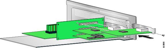
Figure 7-4 Inserting an Expansion Board into a PCI Slot on the PIX 525 Component Tray

Step 6 Figure 7-5 shows circuit boards in PCI slots on the component tray.

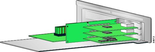
Figure 7-5 Expansion Boards in PCI Slots on the PIX 525 Component Tray

Step 7 Reinstall the component tray into the PIX 525 chassis.


Installing a Circuit Board in a PIX 515

The information in this section refers to both the AC and DC models of the PIX 515.

Use the following steps to install a circuit board in a PIX 515:


Step 1 Locate the grounding strap from the accessory kit. Fasten the grounding strap to your wrist so that it contacts your bare skin. Attach the other end to bare metal inside the PIX 515 chassis as shown in Figure 7-6.

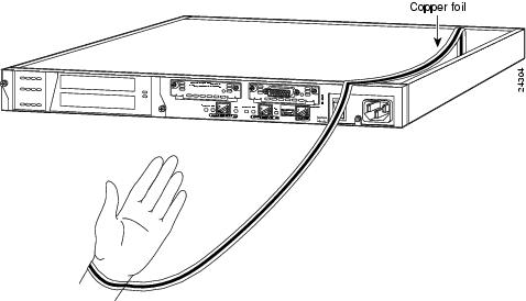
Figure 7-6 Attaching the PIX 515 Grounding Strap

Step 2 Remove the screws from the rear assembly on the left and put the assembly aside.

Step 3 Insert a circuit board through the cage opening and into the slot as shown in Figure 7-7.

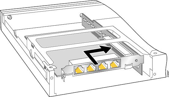
Figure 7-7 Inserting a Circuit Board into a PIX 515


Note When you insert a four-port Ethernet circuit board in the slot, the end of the circuit board's connector extends past the end of the slot. This does not affect the use or operation of the circuit board.


Step 4 Attach the back cover plate making sure that the connecting flange on the circuit board goes through the slot on the back cover plate as shown in Figure 7-8.

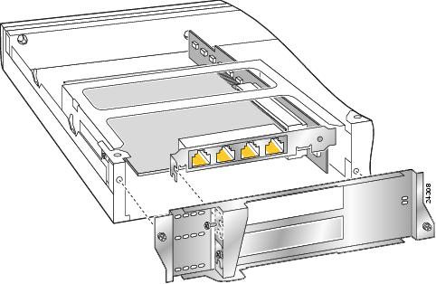
Figure 7-8 Attaching PIX 515 Back Cover Plate

Step 5 Attach the screw to hold the circuit board's connecting flange to the cover plate, and install the screws to attach the cover plate to the PIX 515 unit.

Step 6 Reattach the top panel.


Installing a Circuit Board in a PIX 520 and Earlier Model

Follow these steps to install a circuit board in a PIX 520 and earlier model:


Step 1 Locate the grounding strap from the accessory kit. Fasten the grounding strap to your wrist so that it contacts your bare skin. Attach the other end to bare metal inside the PIX Firewall chassis as shown in Figure 7-9.

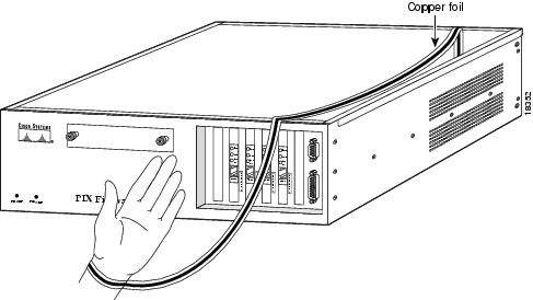
Figure 7-9 Attaching Grounding Strap to Your Wrist and to the PIX Firewall

Step 2 Insert the new circuit board, as shown in Figure 7-10, and secure it using the screw provided with the circuit board.

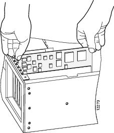
Figure 7-10 Installing the New Circuit Board

Step 3 Figure 7-11 displays how the circuit boards are numbered according to their position. If you have version 4.4 and a four-port Ethernet circuit board, refer to the section, "PIX Firewall with a Four-Port Ethernet Circuit Board" in "Installing a PIX Firewall."


Note When adding a network interface or encryption circuit board, install the new circuit board in the first empty slot to the right of the existing network interface circuit board.


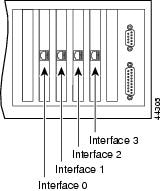
Figure 7-11 PIX Firewall Network Circuit Boards

Step 4 If you are installing a Private Link VPN circuit board, insert the circuit board in any remaining PCI slot after you have installed all of the required circuit boards. Refer to Figure 7-12 for how a PCI slot compares to an ISA slot.

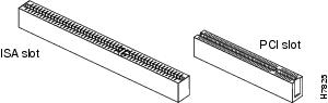
Figure 7-12 Identifying ISA and PCI Slots

Step 5 If you are installing a PIX Firewall Flash memory upgrade, remove the existing Flash circuit board and place the new Flash circuit board into the same ISA slot. If you are installing the PIX Firewall 16 MB Flash circuit board, refer to the section, "PIX Firewall 16 MB Flash Circuit Board" for more details.

Step 6 If you are installing an AccessPro router, the circuit board requires two contiguous ISA slots.

Step 7 If you are installing a 4-port circuit board, note that the circuit board will overlap the slot connector on the motherboard. This does not affect the use or operation of the circuit board. Figure 7-13 illustrates how this appears.

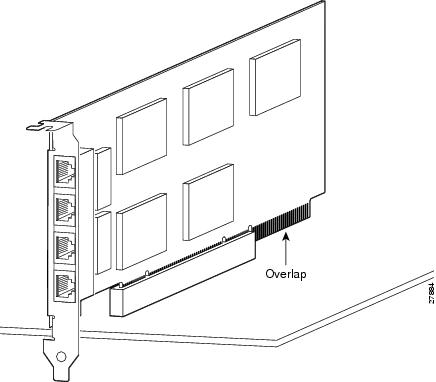
Figure 7-13 4-Port Circuit Board Overlap


PIX Firewall 16 MB Flash Circuit Board

Along with upgrading your Flash memory to 16 MB, the PIX Firewall 16 MB Flash circuit board includes pre-installed PIX Firewall software and a UR (unrestricted) 56-bit DES encryption license. The 16 MB Flash circuit board installs into a PIX Firewall ISA slot.


Note 8 MB or more of Flash is required to install and run PIX software version 5.3(1). The purchase and installation of Flash upgrade PIX-FLASH-16MB= is required for PIX, PIX10000, PIX 510, or PIX 520 revisions A0 through C0 to install version 5.3(1). PIX 520 revisions may be identified by the Flash type as reported in a show version command request. 2 MB models contain the AT29C040A Flash, and 16 MB models contain the i28F640J5 Flash.


An illustration of the 16 MB Flash circuit board is shown in Figure 7-14.

Figure 7-14 PIX Firewall 16 MB Flash Circuit Board

PIX Firewall 16 MB Flash Installation

Use the following information to install a 16 MB Flash circuit board:


Caution You must observe the following when installing a 16 MB Flash circuit board:

The PIX Firewall must have a minimum of 32 MB of RAM memory.

You must obtain a new activation key if you will be using 3DES.

The PIX Firewall should not be downgraded to a software revision lower than 5.0(3) after the new software from the 16 MB circuit board is installed.

If you downgrade from software version 5.3 to 5.2 or lower, you will lose private data (keys, certifications, and CRLs) that are stored in Flash memory. You need to use the clear flashfs command, downgrade 5.0 | 5.1 | 5.2 options if your PIX Firewall has 16 MB Flash memory, private data stored in the Flash memory, and you used the ca save all command to save these items in Flash memory.


Caution Before installing the 16 MB Flash circuit board, you must perform the following steps.

Use the following steps when installing the 16 MB Flash circuit board:


Step 1 Record the present PIX Firewall unit serial number.

Step 2 Record the new serial number from the 16 MB Flash circuit board.

After installation, the serial number of the PIX Firewall will be the serial number supplied with the
16 MB Flash circuit board.

Step 3 Create a backup of your present configuration (to use later to reconfigure your system).

Step 4 Obtain a new Activation key (if using 3DES).

For information on activation keys, see the section, "Upgrading the Activation Key" in "Installing a PIX Firewall."

Step 5 Remove any previously installed Flash memory circuit boards from the unit.

Step 6 The jumper on the PIX Firewall 16 MB Flash circuit board must not be removed or repositioned. The PIX Firewall system will not work if this jumper is moved.

Step 7 Install the 16 MB Flash circuit board into an available ISA slot in a PIX Firewall chassis.

For details and instructions on software installation or upgrades, refer to the Release Notes for the Cisco Secure PIX Firewall Version 5.3(1) or the Configuration Guide for the Cisco Secure PIX Firewall Version 5.3.


PIX Firewall VPN Accelerator Circuit Board

The VPN Accelerator (PIX-VPN-ACCEL) is an encryption and compression accelerator circuit board. The VPN Accelerator uses a PCI interface and therefore can only be installed in PIX Firewall platforms with PCI slots. The VPN Accelerator begins to function immediately after installation without the need of special installation configurations.


Note The new VPN Accelerator cannot be used with the former PIX Firewall IPSec accelerator in the same chassis. The PIX Firewall IPSec accelerator was also known as the Private Link card.


An illustration of the VPN Accelerator is shown in Figure 7-15.

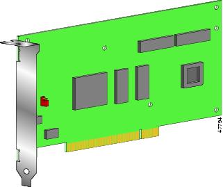
Figure 7-15 PIX Firewall VPN Accelerator Circuit Board

Gigabit Ethernet Circuit Board

PIX Firewall supports 1000 Mbps (Gigabit) Ethernet. The following describes the features and limitations of the optional Gigabit Ethernet circuit board:

The PIX 535 supports up to nine Gigabit Ethernet circuit boards with the unrestricted license. The PIX 535 supports up to six Gigabit Ethernet circuit boards with the restricted license.

The PIX 525 supports up to three Gigabit Ethernet circuit boards with the restricted and unrestricted licenses.

The PIX 520 support up to four Gigabit Ethernet circuit boards.

The PIX 506 and the PIX 515 do not support the Gigabit Ethernet circuit board.

The Gigabit Ethernet circuit board uses the gb-ethernet device name and only has one hardware speed and the following duplex options:

1000sxfull—forces full duplex operation

1000basesx—forces half duplex operation

1000auto—auto negotiates full or half duplex

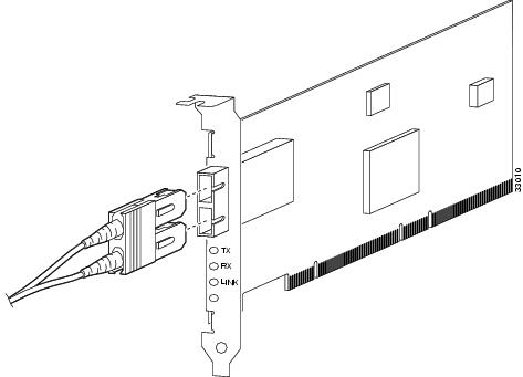
The Gigabit Ethernet circuit board and the fiber optic cable connection are shown in Figure 7-16.

Figure 7-16 Gigabit Ethernet Circuit Board

The Gigabit Ethernet circuit board has three LEDs:

TX—transmitting data

RX—receiving data

LINK—the Gigabit Ethernet circuit board has established a network connection

FDDI Circuit Board

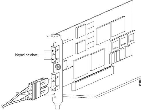
After inserting a FDDI circuit board into a PIX Firewall slot, connect the cable as shown in Figure 7-17.


Note A new FDDI cable may have a protective sleeve over the connector. Remove the protective sleeve before inserting the cable connector into the FDDI circuit board connector.


Figure 7-17 Connecting a FDDI Circuit Board Cable