Feedback
Table Of Contents
Opening a PIX Firewall Chassis
Closing a PIX 510 and PIX 520 Chassis
Opening a PIX Firewall Classic
Opening a PIX Firewall Chassis
The instructions in this chapter describe how to open the top of the PIX Firewall chassis so you can add upgrade boards and system memory.
This chapter includes the following sections, which provide information for each PIX Firewall model:
•
Opening a PIX 510 and PIX 520
•
Note
Note
Note
Note
Opening a PIX 515
Follow these steps to open a PIX 515:
Step 1
Step 2
Warning
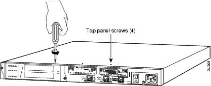
Step 3
Figure 5-1 Removing PIX 515 Top Panel Screws
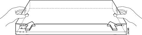
Step 4
Figure 5-2 Pushing Back the Top Panel
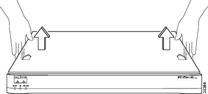
Step 5
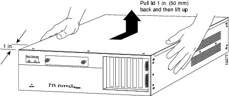
Figure 5-3 Pull the Top Panel up to Remove
Opening a PIX 510 and PIX 520
Follow these steps to open a PIX 510 and PIX 520 chassis:
Step 1
Step 2
Warning
Step 3
Figure 5-4 Removing the Top Panel Screws
Step 4
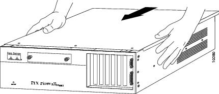
Figure 5-5 Removing the Top Panel
Closing a PIX 510 and PIX 520 Chassis
Replace the top panel, as shown in Figure 5-6, and secure it with the three screws you removed in
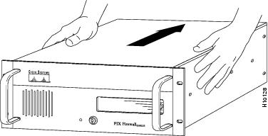
Step 3 in the previous section.Figure 5-6 Replacing the Top Panel
Opening a PIX10000
Follow these steps to open a PIX10000 chassis:
Step 1
Step 2
Step 3
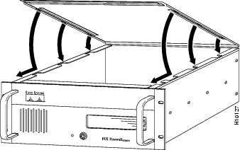
Figure 5-7 Opening the PIX10000 Chassis
Closing a PIX10000
Follow these steps to close a PIX10000 chassis:
Step 1
Figure 5-8 Attach the PIX10000 Top Panel by Matching the Slots
Step 2
Step 3
Step 4
Opening a PIX Firewall Classic
Follow these steps to open the chassis for this model:
Step 1
Step 2
Warning
Step 3
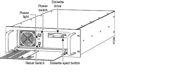
Figure 5-9 Opening the Front Panel Provides Access to the Power Switch
Step 4
Step 5
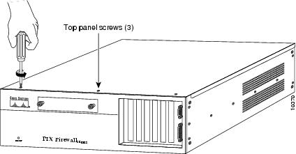
Step 6
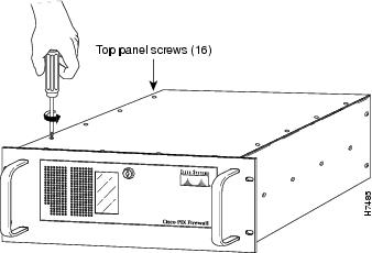
Figure 5-10 Removing the Top Panel Screws
Step 7
Replacing a Lithium Battery
The PIX Firewall has a lithium battery on its main circuit board. This battery has an operating life of about 10 years. When the battery loses its charge, the PIX Firewall cannot function. You must call Cisco Technical Support to replace the battery.
Note
Warning