Feedback
Table Of Contents
Upgrading from PIX Firewall Version 4.1 to Version 4.2
Upgrading from PIX Firewall Version 4.2(1)
Configuring Firewall Units for Failover
Frequently Asked Failover Questions
Compiling Cisco Syslog Enterprise MIB Files
Advanced Configurations
This chapter describes how to configure:
Failover
Use the failover command without an argument after you connect the optional failover cable between your primary firewall and a secondary firewall. The default is failover off. Enter no failover in the configuration file for the PIX Firewall if you will not be using the failover feature. Use the show failover command to verify the status of the connection and to determine which unit is active.
Note
Remove the failover cable before upgrading to a new version of PIX Firewall. Once the new software is installed, configured, and operating properly, then reconnect the cable and reboot the two systems, first the primary and then the secondary. The primary will then automatically update the secondary unit.
Failover is supported only between identical PIX Firewall models running the same software version. For example, failover is not supported between a PIX10000 and a PIX 520.
In PIX Firewall release 4.2, failover IP addresses must be configured on each interface card. The Active unit of the failover pair uses the system IP addresses and the Primary unit's MAC address, while the Standby unit uses the failover IP addresses and the secondary unit's MAC address. The system IP addresses and the failover IP addresses must be on the same subnet with no router between them.
When a failover occurs, each unit changes state. The newly Active unit assumes the IP and MAC addresses of the previously Active unit and begins accepting traffic. The new Standby unit assumes the failover IP and MAC addresses of the unit that was previously the Active unit. Because network devices see no change in these addresses, no ARP entries change or timeout anywhere on the network.
Both PIX Firewall units in a failover pair must have the same configuration. To accomplish this, always enter configuration changes on the Active unit in a PIX Firewall failover configuration. Use the write memory command on the Active unit to save configuration changes to Flash memory (non-volatile memory) on both the active and Standby units. Changes made on the Standby unit are not replicated on the Active unit.
Use the write standby command to manually save the configuration of the active failover unit to the standby failover unit from RAM to RAM. The Standby unit must not be configured individually. Commands entered on the Active unit are automatically replicated on the Standby unit. Only use the default configuration initially. You can force an update by using the write standby command on the Active unit. If you make changes to the Standby unit, it displays a warning but does not update the Active unit.
To save the configuration of the Active unit to Flash memory (permanent memory) on the Standby unit, use the write memory command on the Active unit. The write memory command results are replicated on the Standby unit.
Both units in a failover pair communicate through the failover cable. The two units send special failover "hello" packets to each other over all network interfaces and the failover cable every 15 seconds. The failover feature in PIX Firewall monitors failover communication, the power status of the other unit, and hello packets received at each interface. If two consecutive hello packets are not received within a time determined by the failover feature, failover starts testing the interfaces to determine which unit has failed, and transfers active control to the Standby unit.
The Standby unit does not maintain the state information of each connection. This means that all active connections will be dropped when failover occurs. Client systems must reestablish connections. Additionally, no RIP information is available on the newly Active unit. The newly active PIX Firewall must wait for up to 30 seconds to learn the routing information from the network.
When a failover occurs, syslog messages are generated indicating what happened.
Failover works by passing control to the Standby unit should the Active unit fail. For Ethernet, failover detection should occur within 30 seconds. Token Ring requires additional time for failover.
The markings on the cable let you choose which PIX Firewall unit is primary and which is secondary. You need only connect the failover cable between the PIX Firewall units.
Note
SYSLOG messages indicate whether the primary or secondary unit failed. Use the show failover command to verify which unit is active.
If you want to force a PIX Firewall to be active or go to standby you can use the failover active or no failover active command. Use this feature to force a PIX Firewall offline for maintenance or to return a failed unit to service.
Upgrading from PIX Firewall Version 4.1 to Version 4.2
Step 1
Note
Step 2
Step 3
Step 4
Step 5
Step 6
Step 7
Step 8
Note
Step 9
The primary PIX Firewall becomes the Active unit and begins passing network traffic.
Step 10
Step 11
Step 12
Step 13
This completes the upgrade procedure.
Upgrading from PIX Firewall Version 4.2(1)
Step 1
Note
Step 2
Step 3
Step 4
Step 5
Step 6
Step 7
Step 8
This completes the upgrade procedure.
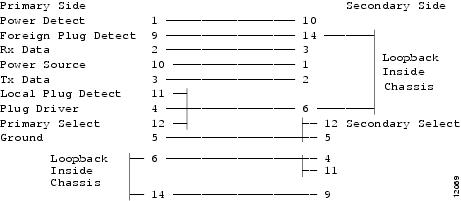
Failover Cable Pinouts
The pin outs for the cable are shown in .
Figure 3-1
Failover Cable Pin Outs
Configuring Firewall Units for Failover
Note
The following guidelines apply to configuring failover on the Active unit:
•
•
Note
•
Frequently Asked Failover Questions
This section contains some frequently asked questions about the failover feature.
•
No, failover will not work without the cable. If you run without the failover cable you are essentially running two separate PIX Firewall units. This will result in a bridge loop and flood the network. The failover cable is an essential part of failover.
•
No, the cable cannot be extended using modems or other RS-232 line extenders. Part of what the failover cable does is indicate the presence and power status of the other unit. When you place line extenders in this path you are relaying the status of the line extender rather than of the other PIX Firewall unit.
•
A switch can be initiated by either unit. When a switch takes place, each unit changes state. The newly Active unit assumes the IP address and MAC address of the previously Active unit and begins accepting traffic for it. The new Standby unit assumes the IP address and MAC address of the unit that was previously the Standby unit. The two units do not share connection states. Any active connections will be dropped when a failover switch occurs. The clients must re-establish the connections through the newly Active unit.
•
When a unit boots up, it defaults to Failover Off and Secondary, unless the failover cable is present or failover has been saved in the configuration. The configuration from the Active unit is also copied to the Standby unit. If the cable is not present, the unit automatically becomes the Active unit. If the cable is present, the unit that has the primary end of the failover cable plugged into it becomes the Primary unit by default.
•
Commands entered on the Active unit are automatically replicated on the Standby unit.
•
When the primary active PIX Firewall experiences a power failure, the standby PIX Firewall comes up in active mode. If the Primary unit is powered up again it will become the Standby unit.
•
When the active PIX Firewall is failed by disconnecting the interface (cable pull), the standby PIX Firewall becomes the Active unit. When the interface is plugged back in, the unit automatically recovers, and its status is changed from failed to standby.
•
Yes, if you are running PIX Firewall version 4.2.x on both units.
•
Fault detection is based on the following:
•
•
•
•
•
•
•
•
SYSLOG messages will be generated when any errors or switches occur. Evaluate the failed unit and fix or replace it.
Failover Interface Tests
If a failure is due to a condition other than a loss of power on the other unit, failover will begin a series of tests to determine which unit is failed. This series of tests will begin when hello messages are not heard for two consecutive 15-second intervals. Hello messages are sent over both network interfaces and the failover cable.
The purpose of these tests is to generate network traffic in order to determine which (if either) unit is failed. At the start of each test, each unit clears its received packet count for its interfaces. At the conclusion of each test, each unit looks to see if it has received any traffic. If it has, the interface is considered operational. If one unit receives traffic for a test and the other unit does not, the unit that received no traffic is considered failed. If neither unit has received traffic, they go to the next test.
Note
•
•
•
•
Failover SYSLOG Messages
In the messages that follow, P|S can be either Primary or Secondary depending on which PIX Firewall is sending the message. Failover messages always have a SYSLOG priority level of 2, which indicates a critical condition. Refer to the logging command description for more information on SYSLOG messages.
To receive SNMP SYSLOG traps (SNMP failover traps), you must configure the SNMP agent to send SNMP traps to SNMP management stations, define a SYSLOG host, and also have compiled the Cisco SYSLOG MIB into your SNMP management station. See the snmp-server and logging command pages in Chapter 5, "" for more information.
The SYSLOG messages sent to record failover events are:
•
•
•
•
•
•
•
•
•
•
•
•
•
•
•
•
•
WebSENSE URL Filtering
If your network has a WebSENSE server on any network interface, you can provide URL filtering through the PIX Firewall.
To configure the PIX Firewall to use WebSENSE:
Step 1
url-server (dmz) host 192.168.1.42 timeout 10In this example, the WebSENSE host is on the dmz interface at IP address 192.168.1.42. A timeout value of 10 seconds is specified as maximum allowed idle time before the PIX Firewall switches to the next WebSENSE server.
Step 2
filter url http 0 0 0 0 allow
Note
Step 3
FTP and URL Logging
You can log FTP commands and WWW URLs when syslog is enabled. FTP and URL messages are logged at syslog level 7.
Refer to the section "Step 15 - Enable Syslog" in Chapter 2, "," for more information on how to view syslog messages on a server, console session, or via Telnet to the console.
Use the show fixup command to ensure that the fixup protocol commands for FTP and HTTP are present in the configuration:
fixup protocol http 80fixup protocol ftp 21These commands are in the default configuration.
The sections that follow provide sample output displays for each logging type.
Sample URL Log
The following is an example of a URL logging syslog message:
192.168.69.71 accessed URL 10.0.0.1/secrets.gifSample FTP Log
The following are examples of FTP logging syslog messages:
192.168.69.42 Retrieved 10.0.0.42:feathers.tar192.168.42.54 Stored 10.0.42.69:privacy.zipYou can view these messages at the PIX Firewall console with the show logging command.
SNMP Traps
The snmp-server command causes the PIX Firewall to send SNMP traps so that the firewall can be monitored remotely. Use snmp-server host to specify which systems receive the SNMP traps.
Note
Browsing a MIB is different from sending traps. Browsing means doing an snmpget or snmpwalk of the MIB tree from the management station to determine values. Traps are different; they are unsolicited "comments" from the managed device to the management station for certain events, such as link up, link down, syslog event generated, and so on.To send traps to an SNMP server:
Step 1
Step 2
Step 3
logging trap debuggingCisco recommends that you use the debugging level during initial set up and during testing. Thereafter, set the level from debugging to a lower value for production use.
Step 4
The PIX Firewall SNMP MIB-II groups available are System and Interfaces.
All SNMP values are read only (RO).
Using SNMP, you can monitor system events on the PIX Firewall. SNMP events can be read, but information on the PIX Firewall cannot be changed with SNMP. The PIX Firewall SNMP traps available to an SNMP server are:
•
•
•
•
•
•
Use CiscoWorks for Windows (Product Number CWPC-2.0-WIN) or any other SNMP V1, MIB-II compliant browser to receive SNMP traps and browse a MIB. SNMP traps occur at UDP port 162.
Compiling Cisco Syslog Enterprise MIB Files
To receive security and failover SNMP traps from the PIX Firewall, compile the Cisco syslog MIB into your SNMP management application. If you do not compile the Cisco syslog MIB into your application, you only receive MIB-II traps for link up or down, and firewall cold and warm start.
You can get the Cisco MIB files on the Web from:
http://www.cisco.com/public/mibs/v2/CISCO-SYSLOG-MIB.my
To compile Cisco syslog Enterprise MIB files into your browser using CiscoWorks for Windows (SNMPc), complete the following steps:
Step 1
Step 2
Step 3
Step 4
Step 5
Step 6
Step 7
Step 8
Step 9
Step 10
Step 11
These instructions are only for SNMPc (CiscoWorks for Windows).
Private Link
The link command creates an encrypted path between Private Link-equipped PIX Firewall units. You can specify up to seven encryption keys for data access between the local unit and the remote unit. The key-ID and key values must be the same on each side of the Private Link. Once you specify the same keys on both sides of the connection, the systems alert each other when a new key takes effect. You can use the age command to specify the number of minutes that a key is in effect.
Note
Specify the link command once for each key you want to specify; for example, if you want seven keys, enter the link command in the configuration seven times.
The PIX Firewall Private Link consists of an encryption card and software that permits the PIX Firewall units to provide encrypted communications across an unsecure network such as the Internet.
The PIX Firewall allows up to 256 Private Links and up to 512 link paths.
At least two PIX Firewall units are required to use Private Link and each system must have the same hardware and software versions.
Private Link works by checking packets that arrive at the PIX Firewall inside interface. If a route link previously created by the linkpath command exists that matches the destination network address, the packet is encrypted and encapsulated in an AH/ESP frame. The frame has a destination address of the remote PIX Firewall and a source address of the local PIX Firewall. When the packet arrives at the remote PIX Firewall unit, the data in the packet is decrypted and then sent through the designated interface to the original IP address specified. No translation takes place on packets that traverse the PIX Firewall Private Link. The addressing and data remains completely unchanged.
If you use the link command to change the interface on which a Private Link tunnel terminates, you must reboot the PIX Firewall on which you made the change. For example, if the Private Link tunnel terminates on the perimeter interface of the foreign PIX Firewall and you change it to terminate on the inside interface of the foreign PIX Firewall, you must reboot the local PIX Firewall on which you changed the configuration.
You can manage remote PIX Firewall units through the Private Link interface.
You can use the linkpath 0.0.0.0 0.0.0.0 foreign_external_ip command to route all outbound traffic on a foreign PIX Firewall to a central PIX Firewall. However, this use has two caveats: there can be only one central PIX Firewall and the other PIX Firewall units must be satellites to it. This implies that the satellites only relay connections to the central and do not communicate among themselves. The second caveat is that the linkpath 0 0 command overrides the default route on the outside interface of the satellite PIX Firewall causing all outbound traffic to flow over Private Link to the central PIX Firewall unit. One use of this feature is when access to the Internet is controlled through one PIX Firewall and the other PIX Firewall units feed their Internet traffic to this one site. This could occur when a central processing facility wants to manage all the Internet IP addresses, let the internal networks use any IP numbering scheme, and have local PIX Firewall units protecting individual departments or sites.
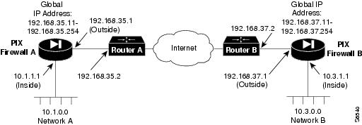
Configuring Private Link
To configure a Private Link, refer to the example shown in .
Figure 3-2 Example Private Link Network Diagram
Before configuring Private Link, you would initially configure the systems using the standard commands.
When you configure a Private Link, follow these steps:
Step 1
Step 2
Step 3
Step 4
link 192.168.37.1 1 fadebacfadebaclink 192.168.37.1 2 bacfadefadebaclink 192.168.37.1 3 baabaaafadebaclink 192.168.37.1 4 beebeeefadebaclinkpath 10.3.0.0 255.255.255.0 192.168.37.1Step 5
link 192.168.35.1 1 fadebacfadebaclink 192.168.35.1 2 bacfadefadebaclink 192.168.35.1 3 baabaaafadebaclink 192.168.35.1 4 beebeeefadebaclinkpath 10.1.0.0 255.255.255.0 192.168.35.1
Note
Step 6
Note
Step 7
Step 8
When you Telnet to the PIX Firewall, and perform a ping inside, the packet is not simply generated from the inside address of the PIX Firewall and forwarded across the bus to the outside address and out the encrypted tunnel. Instead the ICMP packet is placed on the inside network, picked up by the closest router, and retransmitted to the PIX Firewall, where it is then picked up, encrypted and sent across the link to the remote box.