Feedback Feedback
|
Table Of Contents
Cisco Clean Access Installation, Release 3.5
Clean Access Server (CAS) Quick Installation
Clean Access Server Installation Procedure
Clean Access Manager (CAM) Quick Installation
Clean Access Manager Installation Procedure
Install Cisco Clean Access FlexLM License and Access Web Console
Manage the Clean Access Server
Create User Role and Local User (Test)
Configure Traffic Policies for User Roles
Require Use of Clean Access Agent
Make Agent Auto-Upgrade Mandatory
Configure Authentication Servers
Quick Start Guide
Cisco Clean Access Installation, Release 3.5
1 Introduction
This quick start guide is a brief introduction to the major features of the Cisco Clean Access Manager (CAM), Clean Access Server (CAS), web administration console, and Clean Access Agent using local authentication. It is intended to illustrate the minimum steps required to install and configure the CAM and CAS in order to test as Clean Access Agent client on the system. For comprehensive information, including details on configuring network scanning plugins and external authentication servers, refer to the Cisco Clean Access Manager Installation and Administration Guide and Cisco Clean Access Server Installation and Administration Guide, available from http://www.cisco.com/univercd/cc/td/doc/product/vpn/ciscosec/cca/cca35/index.htm
Note that the software installation procedure for the Clean Access Server is the same whether the CAS is in-band (IB) or out-of-band (OOB).
2 In-Band (IB) Deployment
Except where noted, this guide describes basic configuration required for all Cisco Clean Access systems, whether deployment is in-band or out-of-band. Out-of-band deployment requires additional configuration as described below.
3 Out-of-Band (OOB) Deployment
For high-throughput or highly-routed environments, Cisco Clean Access Out-of-Band deployment allows client machines to pass through the Clean Access network only for authentication and certification before being connected directly to the trusted network. Client traffic is considered to be in-band (in the Clean Access network) during authentication and certification, and out-of-band once successfully on the trusted network. With OOB deployment, you can add switches to the Clean Access Manager's domain and control particular switch ports using SNMP. To deploy OOB:
•
Install the latest 3.5.x release of Cisco Clean Access software on your CAM and CAS(es).
•
•
•
•
For complete configuration information, see "Switch Management and Cisco Clean Access Out-of-Band (OOB)" in the Cisco Clean Access Manager Installation and Administration Guide.
4 Clean Access Server (CAS) Quick Installation
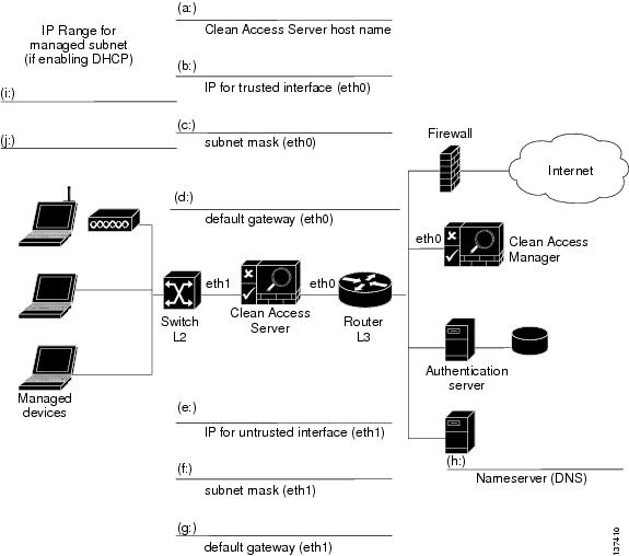
The following worksheet shows the configuration information needed to install the Clean Access Server. Use this worksheet to gather the information specific to your environment. The instructions which follow correlate the information from the worksheet fields with the installation script, clarifying what information is required at each step of the installation.
Figure 1 CAS Installation Worksheet
IP Addressing Considerations
•
•
•
–
–
•
–
Note
•
–
–
–
–
–
Clean Access Server Installation Procedure
Once you have the worksheet information, use the following steps to install the software for the Clean Access Server.
Connect to the target machine:
Step 1
a.
b.
c.
Caution
Step 2
Step 3
a.
b.
The Clean Access Server package installation then executes (this takes a few minutes). When completed, the welcome screen for the Clean Access Server quick configuration utility appears.
Configure the trusted interface (eth0):
Step 4
Step 5
Step 6
Step 7
Step 8
Configure the untrusted interface (eth1):
Step 9
Step 10
Step 11
Step 12
Step 13
Configure nameserver (DNS server):
Step 14
Step 15
Configure shared secret:
Step 16
Configure date and time properties:
Step 17
Generate temporary SSL certificate:
Step 18
a.
b.
c.
Note
Configure passwords:
Step 19
a.
b.
Step 20
Testing the Installation
To test the installation:
•
•
If both tests fail, make sure that you have configured the IP address correctly and that the other network settings are correct.
Note
If after installation you need to reset the initial configuration settings for the Clean Access Server, connect to the CAS machine directly or through SSH and use the CLI command service perfigo config. See Configuration Script for details.
5 Clean Access Manager (CAM) Quick Installation
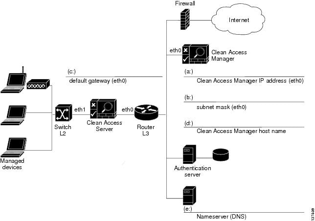
The following worksheet shows the configuration information needed to install the Clean Access Manager. Fill in the fields as appropriate for your environment. The instructions which follow correlate worksheet field information to the installation script.
Figure 2 CAM Installation Worksheet
Clean Access Manager Installation Procedure
Once you have the worksheet information, use the following steps to install the software for the Clean Access Manager.
Connect to the target machine:
Step 1
a.
b.
c.
Caution
Step 2
Step 3
a.
b.
Step 4
Configure the trusted interface (eth0):
Step 5
Note
Step 6
Step 7
Configure nameserver (DNS server):
Step 8
Step 9
Configure shared secret:
Step 10
Configure date and time properties:
Step 11
Generate temporary SSL certificate:
Step 12
a.
b.
c.
Note
Configure password:
Step 13
Note
Step 14
Step 15
Testing the Installation
To test the initial installation, try pinging the Clean Access Manager interface from a command line. If it does not respond, make sure that the CAM machine is properly connected to the network and running.
If necessary, make sure that you have correctly configured network settings at installation by accessing the configuration files directly. For more information, see the Clean Access Manager Installation and Administration Guide.
Configuration Script
If after installation you need to reset the initial configuration settings for either the Clean Access Server or the Clean Access Manager, you can connect to the applicable machine and use the CLI command service perfigo config as described below.
Step 1
Step 2
service perfigo configStep 3
Step 4
service perfigo reboot
6 Install Cisco Clean Access FlexLM License and Access Web Console
Use the following steps to obtain and install your FlexLM license files, and access the Clean Access Manager web administration console. For details on evaluation licenses, see Evaluation Licenses. Note that you must use FlexLM licensing to enable Cisco® Clean Access Out-of-Band (see Out-of-Band (OOB) Deployment for further details).
Step 1
Step 2
Step 3
Step 4
Step 5
Step 6
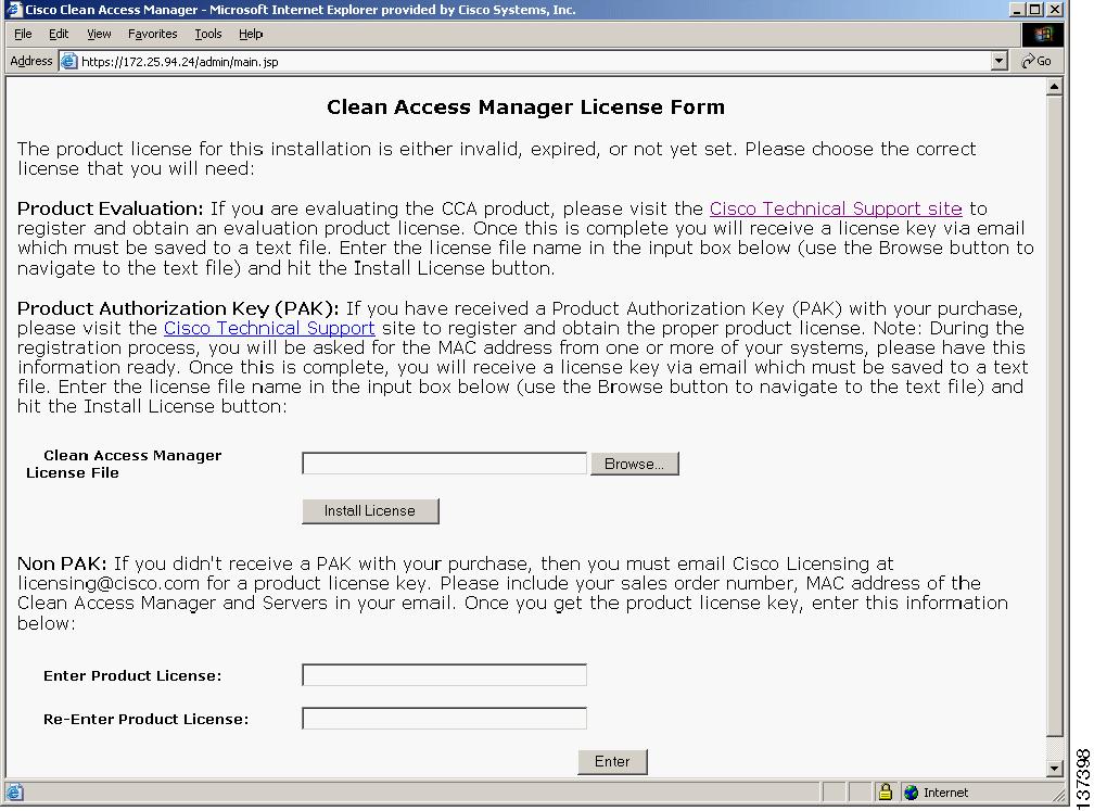
Figure 3 Clean Access Manager License Form
Step 7
Step 8
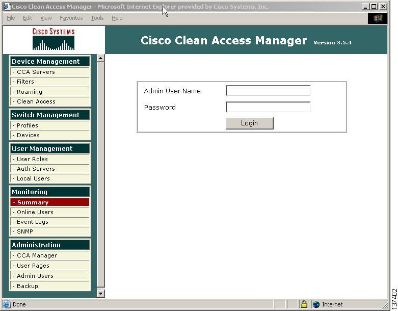
Figure 4 Admin Console Login
Step 9
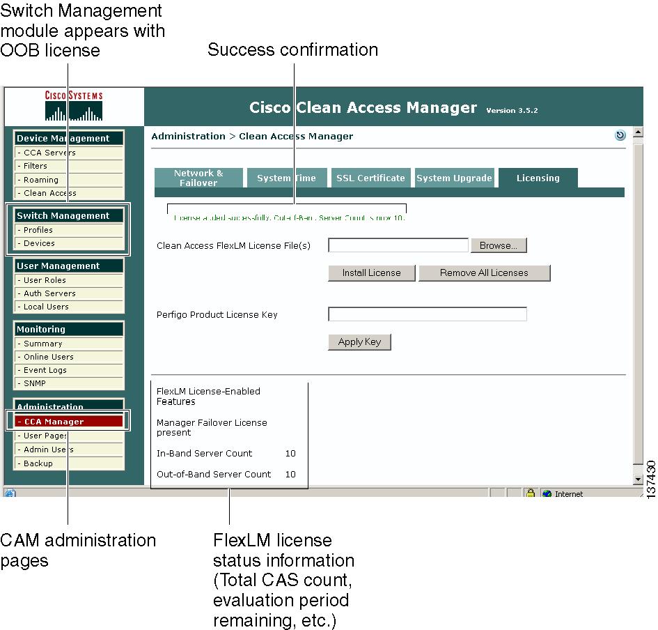
Figure 5 Cisco Clean Access Licensing Administration Page
Step 10
Step 11
Note
A permanent FlexLM license takes precedence and replaces an evaluation FlexLM license. FlexLM licenses (either permanent or evaluation) take precedence and replace legacy (Perfigo) license keys (even though the legacy key is still installed).When an evaluation FlexLM expires, or is removed, an existing legacy license key will again take effect.
Evaluation Licenses
To evaluate the Cisco Clean Access product, an official PAK is not required. An evaluation license enables:
•
•
•
•
•
You do not need to submit MAC addresses for your machines to obtain an evaluation license. Use the following steps to obtain and install an evaluation license file.
Caution
Step 1
Step 2
Step 3
Step 4
Step 5
Step 6
Note
7 Add a Clean Access Server
Once you have installed valid licenses and accessed the web admin console, configure the installation using information from the CAS Installation Worksheet and CAM Installation Worksheet.
Step 1
Step 2
Step 3
Step 4
Step 5
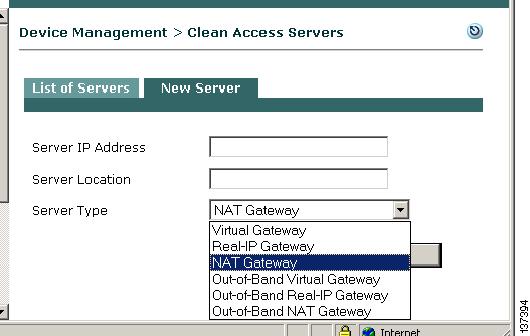
Step 6
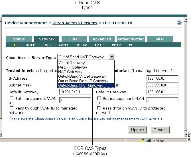
For in-band operation, choose one of the following CAS operating modes as appropriate for your environment:
a.
b.
c.
Note
For out-of-band operation, the Out-of-Band Server Types appear in the dropdown menu when you apply an OOB (Switch Management) enabled license to a Clean Access deployment. For OOB, the CAS operates as a Virtual, Real-IP, or NAT Gateway while client traffic is in-band (in the Clean Access network) during authentication and certification. Once clients are authenticated and certified, they are considered "out-of-band" (no longer passing through the Clean Access network) and allowed directly onto the trusted network. Choose one of the following operating modes for the CAS:
d.
e.
f.
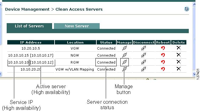
Step 7
Note that the Clean Access Manager can control both IB and OOB Clean Access Servers in its domain, but the CAS itself is either an IB or OOB server.
Note
Make sure the CAS is pingable. If not, the network settings may be incorrect. Reset them using service perfigo config.
The CAM and CAS must have the same shared secret. If this is the problem, reset the shared secret with service perfigo config.
In Virtual Gateway mode, ensure that the CAM and CAS are on different subnets.
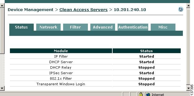
8 Manage the Clean Access Server
Step 1
Step 2
Step 3
Figure 6 CAS Management Pages (Status Tab)
Note
Step 4
Step 5
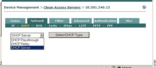
9 Set Up DHCP
If using a Real-IP or NAT Gateway configuration for the server, configure DHCP settings as described below. If a DHCP server already exists in your environment, it may be easiest to relay to that server for initial testing purposes. See the Clean Access Server Installation and Administration Guide for further details on DHCP configuration in the CAS.
Step 1
Step 2
a.
b.
c.
Step 3
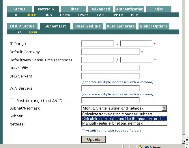
The next step is to configure the IP pool from which client addresses are assigned using fields (i) and (j) from the CAS Installation Worksheet.
Step 4
Step 5
•
•
•
•
•
•
•
•
–
–
–
For this example, select Calculate smallest subnet for IP range entered.
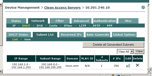
Step 6
Step 7
Step 8
Step 9
Step 10
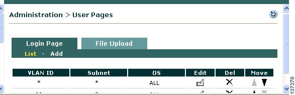
10 Add Default Login Page
A default login page must exist to allow all managed users (web login or Clean Access Agent) to authenticate. The login page appears to web login users whenever they open a web browser to access the network. Before full deployment, you can customize the page to reflect your organization.
Step 1
Step 2
Step 3
Step 4
Step 5
Edit Login Page
To modify a login page configuration later, click the Edit button next to the page under Administration > User Pages > Login Page > List. This brings up the following configuration options:
•
•
•
For complete details, see the Cisco Clean Access Manager Installation and Administration Guide.
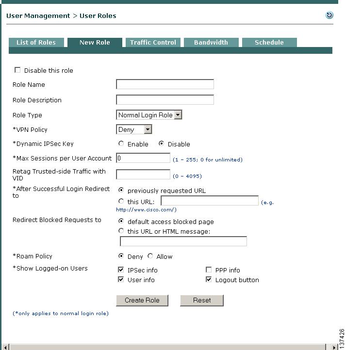
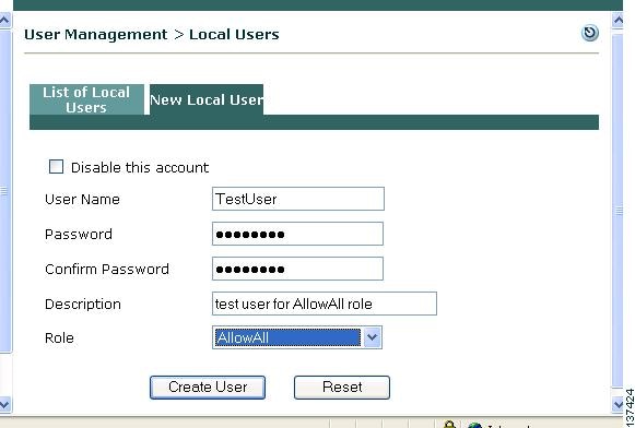
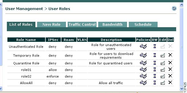
11 Create User Role and Local User (Test)
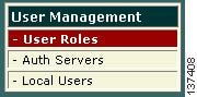
Cisco Clean Access puts users in roles when users log into the Clean Access network (out-of-band users are put into roles during the time that they are in-band). User roles aggregate a variety of user policies in the system, including traffic, bandwidth, application of network scanning plugins, and Clean Access Agent host requirements. The steps below show how to create a normal login role, then create a test local user to authenticate into that role. (Local users are validated by the Clean Access Manager and are used primarily for testing.) Once the role is created, you can configure the associated policies for the users in the role.
Step 1
Step 2
Step 3
Step 4
Step 5
Step 6
a.
b.
c.
d.
e.
Step 7
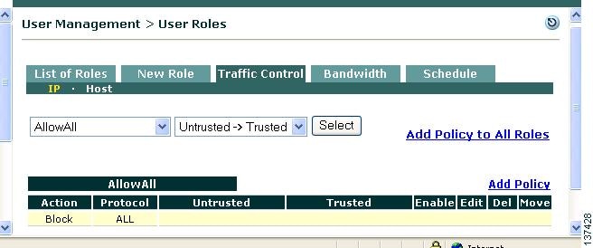
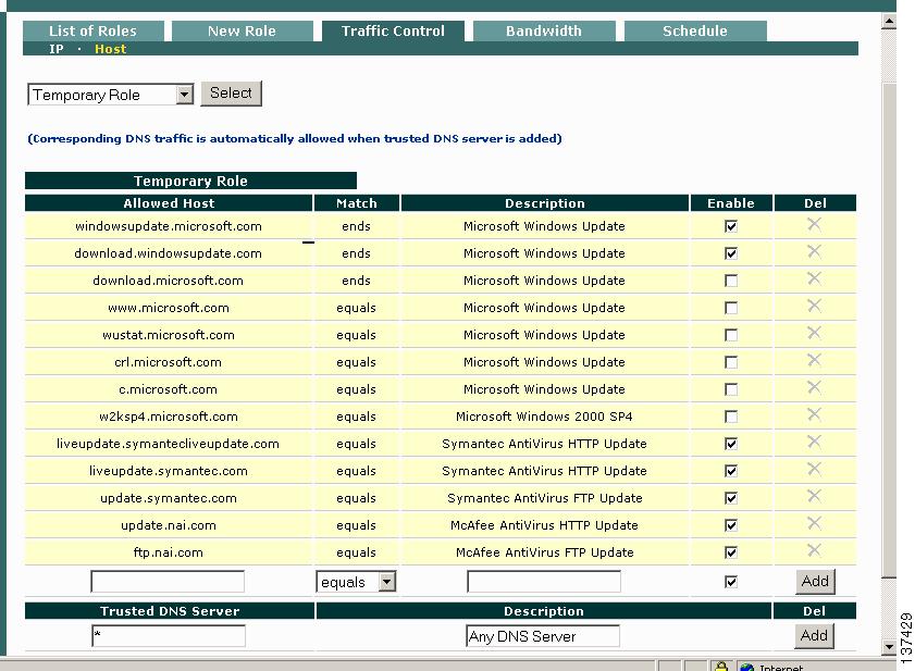
12 Configure Traffic Policies for User Roles
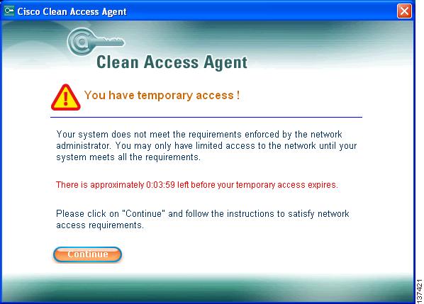
By default, when a new normal login role is created, all client-side traffic originating from the untrusted network is blocked and all CAM/CAS-side traffic originating from the trusted network is allowed. After a normal login user role is created, Untrusted -> Trusted traffic control policies need to be configured to allow users to send and receive traffic while logged into that role. When users log into the network using the Clean Access Agent, the system first puts them in the system Temporary role while determining whether they meet host requirements. If they do, users are allowed on the network in the normal login role to which their user credentials are associated. If clients fail requirements, users stay in the Temporary role until they meet requirements or reach session timeout. (If using network scanning, clients that fail scan plugins can be put in a quarantine role or blocked from the network. See the Cisco Clean Access Manager Installation and Administration Guide for details on network scanning.)
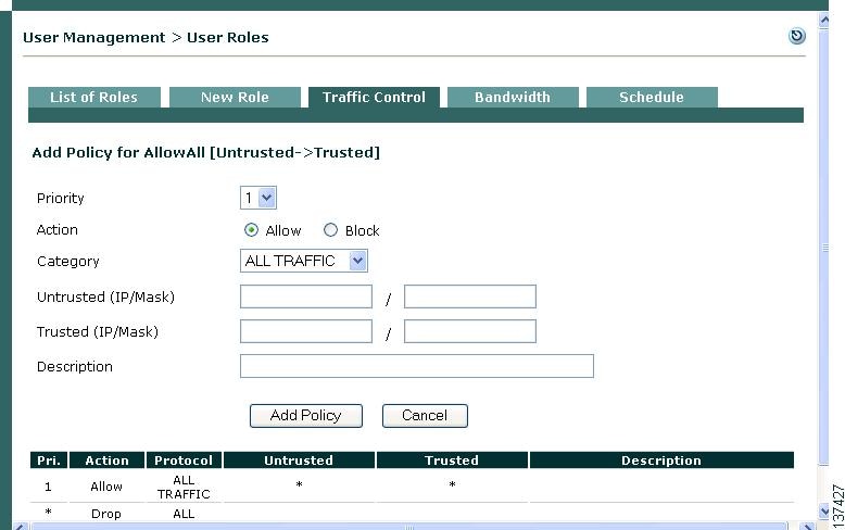
Step 1
Step 2
Step 3
Step 4
a.
b.
c.
d.
Note
Step 5
Step 6
Step 7
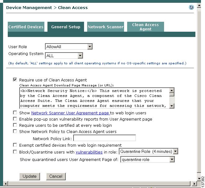
13 Require Use of Clean Access Agent
New users are presented with a webpage from which they can download the setup executable to install the Clean Access Agent the first time they open a web browser and perform a web login (see Figure 8). Once the Clean Access Agent (version 3.5.1 or above) is downloaded to clients, you can configure the Agent to be automatically updated on clients via the web administration console (see Make Agent Auto-Upgrade Mandatory).
Step 1
Step 2
Step 3
Step 4
Step 5
Step 6
14 Make Agent Auto-Upgrade Mandatory
With Cisco Clean Access 3.5.1 or above installed on the CAM and CAS, and Clean Access Agent 3.5.1 or above installed on clients, you can enable mandatory or optional Agent auto-upgrade for all Clean Access Agent users. To make Agent auto-upgrade mandatory, use the following steps.
Step 1
Step 2
Step 3
Step 4
Step 5
Step 6
When users reboot or exit/restart their Clean Access Agent, they will see a prompt to upgrade to a newer Agent when an update patch is downloaded to the CAM and made available to the CAS. The user must click OK (mandatory upgrade) and the client automatically installs the newer Agent. If auto-upgrade is left as optional, users will still see a prompt when they reboot or exit/restart their Agent, but they have the option of clicking Yes to install it immediately or No to postpone the upgrade.
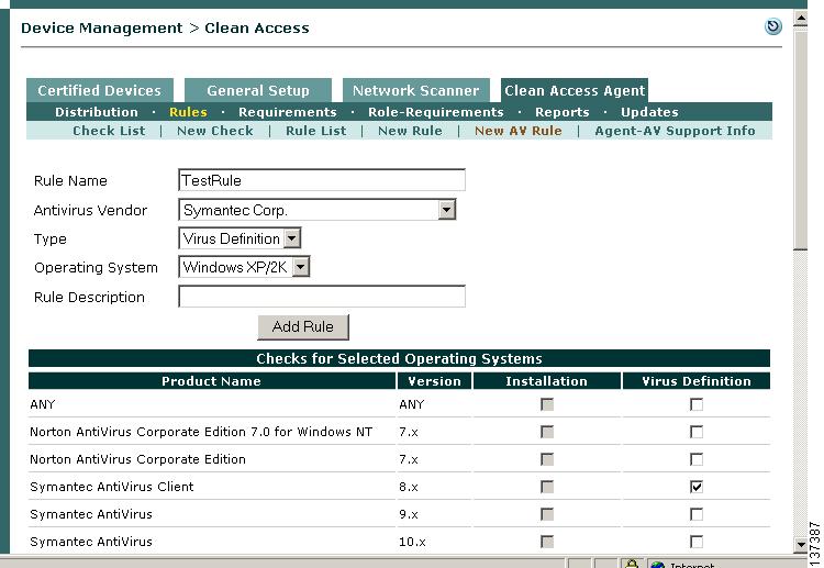
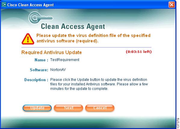
15 Configure an AV Requirement
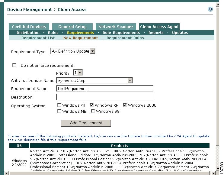
Once you have enforced use of the Clean Access Agent on a role, you can configure a variety of requirements to make sure users trying to log into the role have required packages on their systems (e.g. hotfixes, antivirus software or virus definition files) or alternatively, block users who have undesirable software installed. The following example shows how to configure a Clean Access Agent AV Definition Update requirement that checks if Symantec antivirus definition files are up-to-date on a Windows XP or 2000 client. For complete details on how to configure Clean Access Agent AV and custom requirements in the web admin console, see the Cisco Clean Access Manager Installation and Administration Guide. In this example, the general configuration steps are as follows:
3.
4.
5.
Update your CAM
Step 1
Step 2
Step 3
Step 4
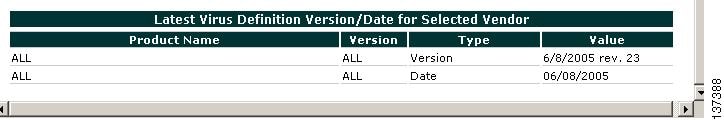
Create New AV Rule
Step 5
Step 6
Step 7
Note
Step 8
Step 9
Step 10
Step 11
Note
Step 12
Note
Step 13
Note
Create New AV Definition Update Requirement
Step 14
Step 15
Step 16
Step 17
Step 18
Step 19
Step 20
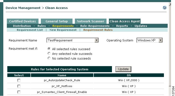
Map AV Definition Update Requirement to AV Definition Rule
Step 21
Step 22
Step 23
Step 24
Step 25
Step 26
Step 27
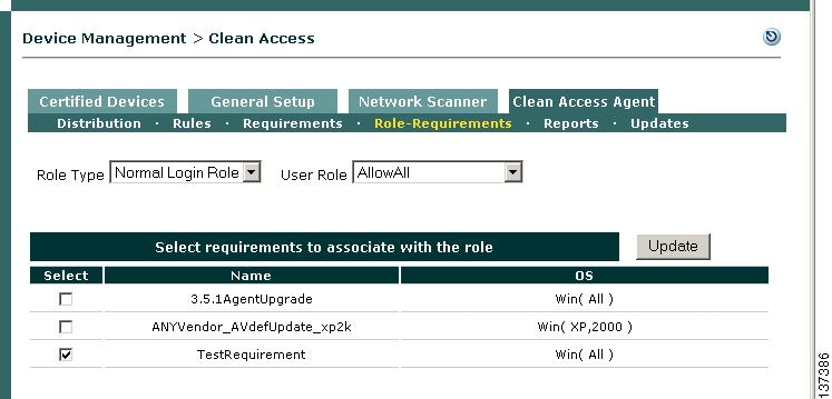
Map AV Definition Update Requirement to User Role
Step 28
Step 29
Step 30
Step 31
Step 32
16 Test as a Managed Client
The easiest way to test Clean Access as an actual user is to connect a client computer to a switch connected to the untrusted (eth1) interface of the Clean Access Server and perform the following tests.
Step 1
a.
b.
Note
Step 2
a.
b.
c.
Note
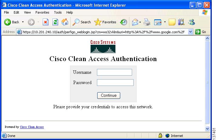
Figure 7 Web Login Page
.
Note
Step 3
Step 4
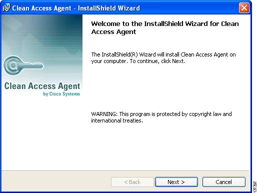
Figure 8 Clean Access Agent Download Page
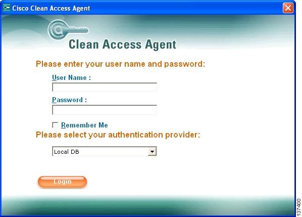
Step 5
Step 6
.
Step 7
Step 8
.
There are four options:
•
•
•
•
Note
Step 9
Step 10
Step 11
Step 12
Step 13
Step 14
Step 15
Note
Step 16
Tip
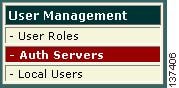
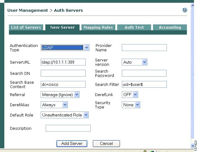
17 Configure Authentication Servers
To integrate Cisco Clean Access with an existing authentication server, you will need to know the configuration parameters for the type of authentication server you want to use. These can include the location of the authentication server, connect strings, and so on. Use the following steps once you have the information applicable for your authentication source.
Step 1
Step 2
Step 3
Step 4
Step 5
Step 6
Step 7
See the Cisco Clean Access Manager Installation and Administration Guide for details on configuring mapping rules to map users into user roles based on VLAN ID or LDAP/RADIUS authentication server attributes.
18 User Authentication Test
Before testing an external authentication server as an actual user, there is a simple user authentication test that can validate your authentication server parameters immediately in the web admin console.
Step 1
Step 2
Step 3
Note
Step 4