-
Cisco NAC Appliance - Clean Access Server Configuration Guide, Release 4.9(2)
-
About This Guide
-
Introduction
-
Planning Your Deployment
-
Configuring Layer 3 Out-of-Band
-
Configuring the CAS Managed Network
-
Configuring DHCP
-
Integrating with Cisco VPN Concentrators
-
Local Traffic Control Policies
-
Configuring Active Directory Single Sign-On
-
Local Authentication Settings
-
Local Certified and Floating Devices
-
Administering CAS Certificates, Time, and Support Logs
-
MIB Support
-
Open Source License Acknowledgements
-
 Feedback
Table Of Contents
Configure DHCP Relay or DHCP Server Mode
Configuring IP Ranges (IP Address Pools)
Auto-Generated versus Manually Created Subnets
Auto-Generating IP Pools and Subnets
View Users by MAC Address/VLAN
View or Delete Subnets from the Subnet List
Configuring a Real-IP CAS as DHCP Server for L3 Clients
Configuring DHCP
In the majority of deployments, a DHCP server already exists on the network, and the Clean Access Server needs to be configured in either DHCP Relay or DHCP Passthrough mode. DHCP Relay mode can be used when a CAS is a Real-IP Gateway, and DHCP Passthrough is used exclusively for a CAS in Virtual Gateway mode. For a lab/test environment, or if a DHCP server is not already set up, you can configure a Real-IP Gateway CAS to be the DHCP Server for your network. This chapter describes how to configure each of the DHCP modes of the Clean Access Server. Topics include:
•
Configuring IP Ranges (IP Address Pools)
Overview
DHCP (Dynamic Host Configuration Protocol) is a broadcast protocol for dynamically allocating IP addresses to computers on a network. When a client computer attempts to join a DHCP-enabled network, the client broadcasts an address request message. A DHCP server on the network responds to the request, and through the course of several exchanges, an IP address is negotiated for and delivered to the client.
In a DHCP-enabled network, the Clean Access Server can operate in one of several modes:
•
•
•
When a Real-IP Gateway CAS is enabled as a DHCP Server, it provides the services of a full-featured DHCP server. It can allocate addresses from a single IP pool or from multiple pools across many subnets. It can assign static IP addresses to particular client devices.
The DHCP Server configuration interface includes tools for auto-generating IP pools, making it easier to create many pools at once, and provides checking mechanisms to help detect configuration errors.
Auto-generating IP pools as a response to heightened virus activity can help to protect your network. By segmenting your network into many small subnets (such as /30 subnets), you can isolate clients from one another. Since clients cannot communicate directly across subnets, all traffic between them is routed through the Clean Access Server, limiting the ability of worms to propagate over peer-to-peer connections.
When you generate subnetted IP address pools, the Clean Access Server is automatically configured as the router for the subnet. An ARP entry for the subnet is automatically generated as well.
For static addresses, you can reserve a particular IP address for a particular device by MAC address.
Table 5-1 Recommended DHCP limits
DHCP IP lease recommended limit of pool size
5000
Default/Min-Max lease time
0-2147483647 seconds
Recommended lease time
1800-7200 seconds
Note
Enable the DHCP Module
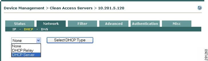
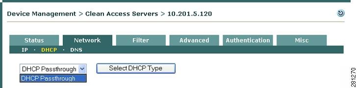
You can enable DHCP Relay or DHCP Server mode on a Clean Access Server that is in Real-IP Gateway mode. When a CAS is a Virtual Gateway, it is always in DHCP Passthrough mode (see Figure 5-4).
Configure DHCP Relay or DHCP Server Mode
1.
2.
Figure 5-1 Select DHCP Type (CAS in Real-IP Gateway Mode)
3.
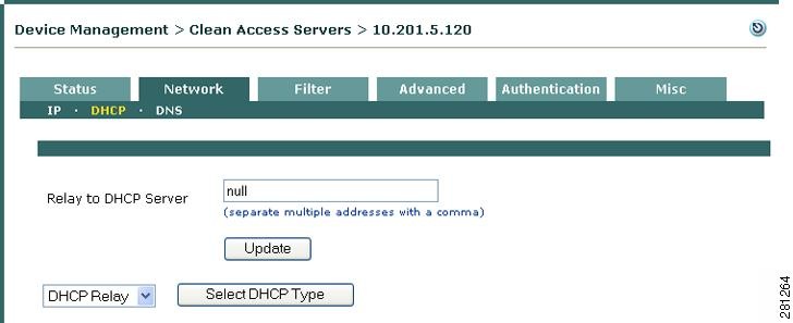
a.
b.
Figure 5-2 Configuring DHCP Relay
c.
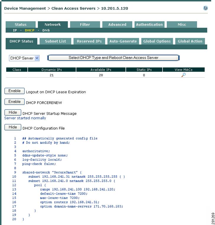
Figure 5-3 DHCP Server Mode
Note
DHCP Status Options
When the CAS is enabled as a DHCP server, the DHCP Status tab includes the enable buttons shown in Figure 5-3.
Cisco NAC Appliance offers two DHCP enable/disable functions to ensure client IP addresses are renewed properly when the CAS is configured as the DHCP server for your network. These are User Logout on DHCP Lease Expiration and DHCP FORCERENEW, as described below.
Enable/Disable Logout on DHCP Lease Expiration
This toggle button is disabled by default. Clicking the Enable button causes the user to be logged out (either Agent or Web session logout) from the Cisco NAC Appliance when the client's DHCP lease expires.
Enable/Disable DHCP FORCERENEW
This toggle button is disabled by default. Clicking the Enable button instructs the DHCP server to execute a DHCP NAK command, which releases IP addresses assigned to a client by other DHCP servers. Following the NAK command, the DHCP client will be assigned a valid IP address as configured on the CAS.
Show/Hide DHCP Server Startup Message
When this button is clicked, the last DHCP server startup message is displayed. If the server does not start, an error message is shown here.
Show/Hide DHCP Configuration File
When this button is clicked, the DHCP configuration file is displayed. In some cases, the startup message displays an error for a particular line of the configuration. Clicking this button allows you to view the configuration file line-by-line.
For further information on the DHCP Status tab see Working with Subnets.
For additional information on DHCP configuration, see User-Specified DHCP Options.
Note
Figure 5-4 CAS VGW DHCP Type
Configuring IP Ranges (IP Address Pools)
To set up the Clean Access Server to provide DHCP services, you first configure the range of IP addresses to be allocated to clients (the IP address pool). In addition, you can specify network information to be handed to clients with the address, such as DNS addresses.
The CAS can allocate addresses from multiple pools and subnets. However, allocated addresses must fall within the ranges specified to be managed by the CAS. This can be either:
•
•
If you try to create an address pool from a subnet that is not managed, an error message notifying you of the condition appears in the admin console and the pool is not created.
Auto-Generated versus Manually Created Subnets
You can automatically generate subnets in order to create many IP address pools at a time. Creating a large number of IP pools of relatively small size (from which only a few addresses can be assigned) can help protect your network. By isolating clients into small subnets, you limit the ability of peers to communicate directly with one another, and thereby prevent events such as worms from proliferating across peer connections.
Alternatively, you can manually create subnets if only a few IP address pools are required for your network.
Subnetting Rules
Whether creating IP pools automatically or manually in the admin console, the subnets you create must follow standard subnetting design rules. Only properly aligned, power-of-two subnet addresses are supported. For example, you cannot start a subnet range at address 10.1.1.57 with a subnet mask of 255.255.255.192, because the final octet of the netmask, 192, corresponds to a "size 64" subnet. There can only be four size-64 subnets, with subnet start address boundaries of .0, .64, .128, and .192. Since .57 is not a power-of-two, it cannot be used as the starting address for a subnet.
You must specify the starting address of the range for either manually-created or automatically-generated subnets. To manually create a pool you specify the end of the range, and to auto-generate a pool you specify the number of subnets to generate.
Addresses in the IP range are assigned as follows:
1.
2.
3.
4.
By specifying an IP range of only four addresses, you can create a subnet for a single host.
Table 5-2 shows the number of leasable addresses for each subnet size and number of subnets possible per CIDR (Classless InterDomain Routing) prefix. Each CIDR prefix corresponds to a specific subnet mask. CIDR notation identifies the number of bits masked for the network portion of a 32-bit IP address in order to produce a specific number of host addresses. For example, a CIDR address of 10.5.50.6 /30 indicates that the first 30 bits of the address are used for the network portion, leaving the remaining 2 bits to be used for the host portion. Two bits of address yield four host addresses: three addresses are automatically allocated for the required network, gateway, and broadcast addresses for the subnet, and the remaining address can be leased. Therefore, a /30 network creates a subnet of one host.
Table 5-3 shows the addressing for an automatically-generated IP range of four /30 subnets starting at address 10.1.100.12.
In general, the admin console enforces rules for properly configured subnets. If you attempt to use an invalid network address for the netmask, the message appears: "Subnet/Netmask pair do not match". In this case, choose a new value for the address.
Create IP Pools Manually
To create an IP pool manually, you also need to define the subnet in which the pool resides. There are three ways to arrive at the subnet address and netmask values for a manually generated pool:
•
•
•
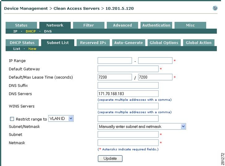
To create an IP pool range:
1.
Figure 5-5 New Subnet List Subtab Link
2.
Figure 5-6 New Subnet Form
3.
–
–
–
–
–
–
–
If choosing VLAN ID, type the VLAN ID in the text field. Clients not associated with the specified VLAN cannot receive addresses from this IP pool. A VLAN ID can be any number between 0 and 4095.
Note
If choosing RELAY IP, type the Relay IP in the text field. Clients not associated with the specified Relay IP cannot receive addresses from this IP pool.
Note
4.
–
–
–
–
5.
Auto-Generating IP Pools and Subnets
By automatically generating subnets, you can quickly divide your network into small segments. Segmenting your network into small subnets can be an effective security measure in response to a worm attack, since a network comprised of many small subnets (with one host per subnet possible) limits the ability of clients to engage in peer-to-peer interaction.
Caution
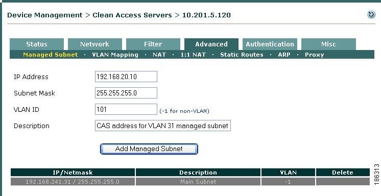
Add Managed Subnet
1.
Figure 5-7 Add Managed Subnet
Note
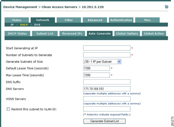
Create Auto-Generated Subnet
1.
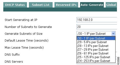
Figure 5-8 DHCP—Auto-Generate Subnet Form
2.
The first available valid address for the managed subnet range is used as the network address for the first subnet, the next number is used as the router address, and the next number after that becomes the first address that is leasable to clients.
3.
4.
–
–
–
Therefore, a /30 size subnet has four addresses, but only one IP available for hosts.
5.
–
–
–
–
–
–
–
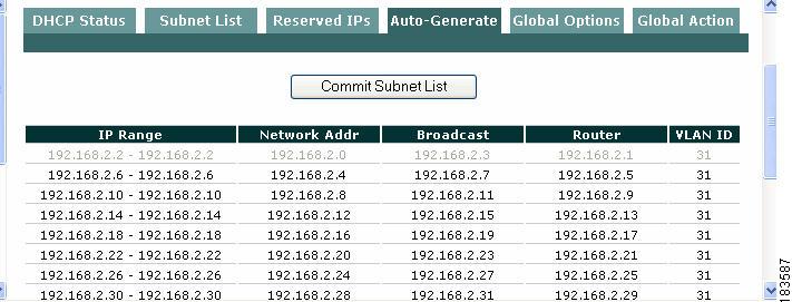
6.
If successful, a preliminary list of IP ranges appears, allowing you to review the results.
Figure 5-9 Commit Subnet List
7.
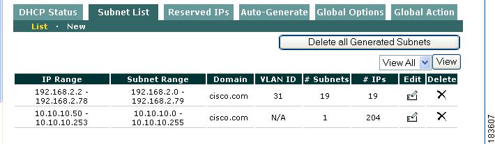
8.
Figure 5-10 Subnet List— List
\
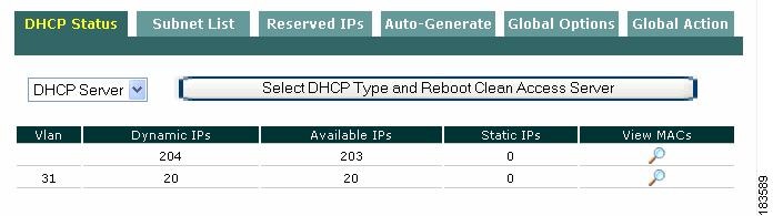
9.
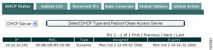
Figure 5-11 DHCP Status
Note
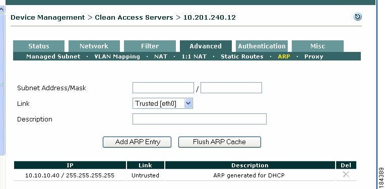
Figure 5-12 ARP Entries Generated for DHCP
Working with Subnets
View Users by MAC Address/VLAN
1.
Figure 5-13 DHCP Status —VLANs
2.
Figure 5-14 View MAC Address
–
–
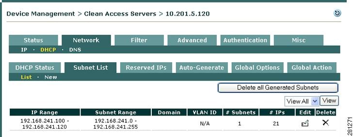
View or Delete Subnets from the Subnet List
1.
Figure 5-15 Subnet List—List
2.
3.
4.
Edit a Subnet
1.
Figure 5-16 Edit Subnet List
2.
3.
Configuring a Real-IP CAS as DHCP Server for L3 Clients
Typically, when a Clean Access Server is configured as a DHCP server it is in Layer 2 mode. The CAS acts as a DHCP server for the Layer 2 VLANs which are trunked to it. In Layer 2 mode, you configure a DHCP scope for that VLAN on the CAS and then configure a managed subnet for that VLAN so that the CAS can communicate to clients in that VLAN.
However, Layer 3 clients are one or multiple hops away from the CAS and therefore work differently. L3 clients are not adjacent to the CAS and DHCP discover broadcast from these clients will never reach the CAS (DHCP server). Therefore, a DHCP scope for these clients cannot be created based on VLAN.
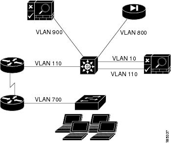
Figure 5-17 illustrates an example scenario.
Figure 5-17 Example L3 Scenario
In this example:
•
•
•
•
As previously mentioned, DHCP discover broadcast from these L3 clients are not able to cross the VLAN 700 boundary. Therefore, an "IP helper address" needs to be configured under the router interface acting as the gateway for VLAN 700, for example:
Interface vlan 700Ip address 10.60.60.1 255.255.255.0ip helper-address x.x.x.xWhere
x.x.x.xis the untrusted side (eth1) IP address of the CAS (e.g. 10.20.20.1).On the CAS, the following needs to be configured:
•
•
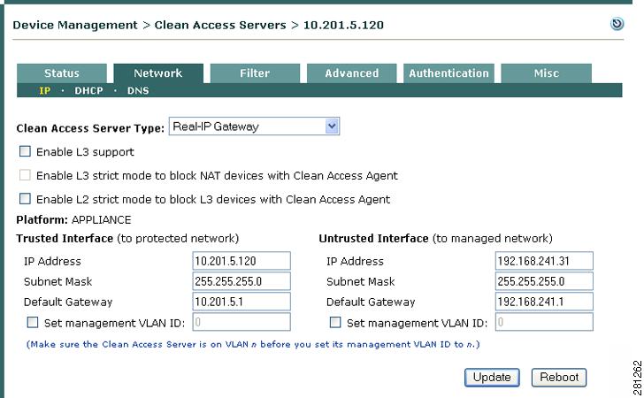
Figure 5-18 shows the IP information of the CAS configured as a Real-IP Gateway:
•
•
•
•
Figure 5-18 CAS IP Configuration
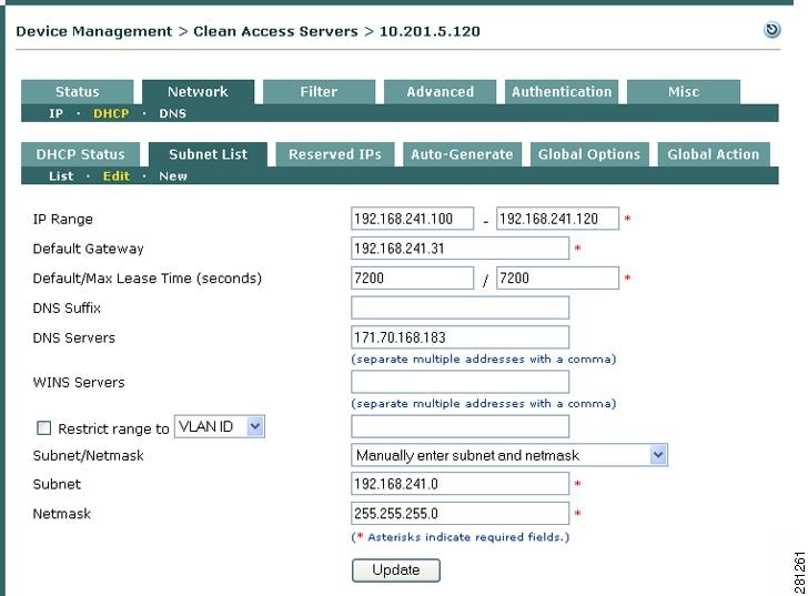
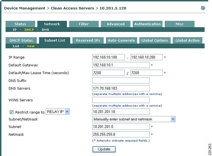
The CAS has already been enabled as a DHCP Server (as described in Enable the DHCP Module). Figure 5-19 shows the New Subnet list form configured under Device Management > CCA Servers > Manage [CAS_IP] > Network > DHCP > Subnet List > New with:
•
•
•
•
•
Figure 5-19 Restrict Subnet List to Relay IP
Figure 5-20 shows the Static Routes form configured under Device Management > CCA Servers > Manage [CAS_IP] > Advanced > Static Routes with:
•
•
•
•
Figure 5-20 Create Static Route
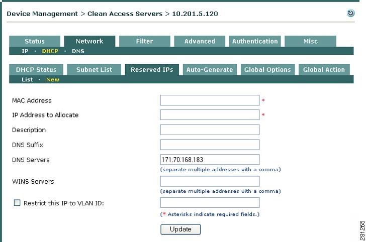
Reserving IP Addresses
By reserving an IP address, you can keep a permanent association between a particular IP address and device. A reserved device is identified by MAC address. Therefore, before starting, you need to know the MAC address of the device for which you want to reserve an IP address. The configuration for a reserved IP does not include a maximum or default lease time. The address is always available for the device and in effect has an unlimited lease time. Table 5-4 lists several rules that apply to reserved IP addresses.
Add a Reserved IP Address
1.
Figure 5-21 Reserved IPs—New
2.
3.
4.
5.
–
–
–
–
6.
The reserved IP now appears in under Subnet List > List. From there, it can be modified by clicking the Edit button or removed by clicking Delete.
User-Specified DHCP Options
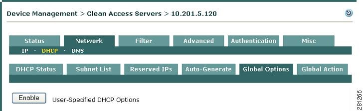
The Global Options tab (Figure 5-22) allows advanced users to modify the DHCP configuration directly. DHCP options can be specified as follows:
•
•
•
You can create DHCP option rules based on class restrictions to restrict access to DHCP subnets. You can create rules for:
•
•
You can create new options by selecting the options type or by creating a custom option to create an option that is not on the list, or of a different type.
Caution
A server directive instructs the DHCP server to behave differently, while a DHCP option refers to a specific piece of data to be returned by the DHCP server. For example, the "allow-bootp" server directive (disabled by default) instructs the DHCP server to allow older BOOTP clients to connect. See Table 5-5 "DHCP Server Directives" for additional details.
Note
Enable User-Specified DHCP Options
1.
Figure 5-22 DHCP Global Options - Enable
2.
–
–
–
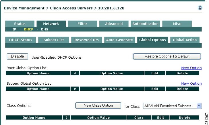
Once an option is added, it is displayed on this main page under the corresponding list name.
Figure 5-23 DHCP Global Options
Note
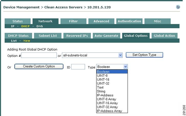
If the desired option number is not known, or if specifying a server directive which changes server behavior but has no corresponding DHCP option number, then select the name of the option or directive from the dropdown menu next to the Set Option Type button. In either case, click the Set Option Type button after the desired DHCP option type has been selected.
DHCP option numbers are specified in RFC 2132.
Add Root Global DHCP Option
3.
Figure 5-24 DHCP Global Options - New Root Global (Custom Option)
4.
5.
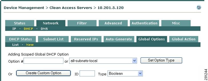
Add Scoped Global DHCP Option
6.
Figure 5-25 DHCP Global Options - New Scoped Global
7.
8.
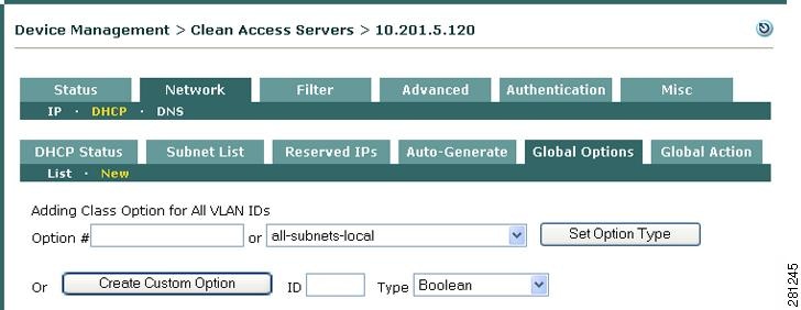
Add New Class Option
9.
–
–
–
–
10.
Figure 5-26 DHCP Global Options - New Class Option For All VLAN IDs (VLAN Restricted Subnets)
11.
12.
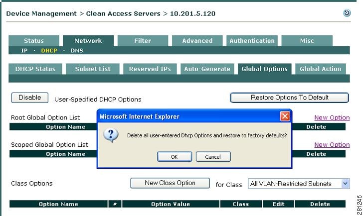
Restore Options to Default
13.
Figure 5-27 Restore Global Options to Default
Disable DHPC Options
To disable admin-specified DHCP options, click the Disable button at the top-left side of he Global Options > List page (Figure 5-23).
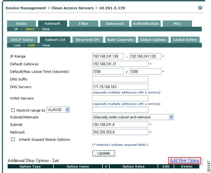
Add Local Scoped DHCP Option
1.
2.
3.
Figure 5-28 Edit Subnet List Form (Local Scoped DHCP Option
)
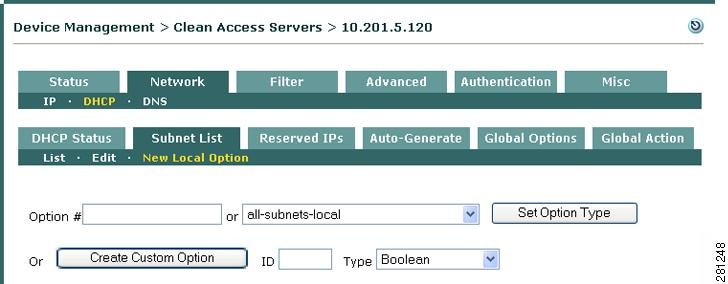
4.
Figure 5-29 Add New Local Option
5.
6.
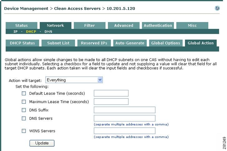
Global Action
The Global Action tab allows you to change fields on all DHCP elements of a particular CAS. For example, if you have 300 managed subnets and IP pools and you need to change the DNS server in all of them, you can achieve this using the Global Action form.
1.
Figure 5-30 Global Action
2.
–
–
–
–
–
3.
–
–
–
–
–
–
4.
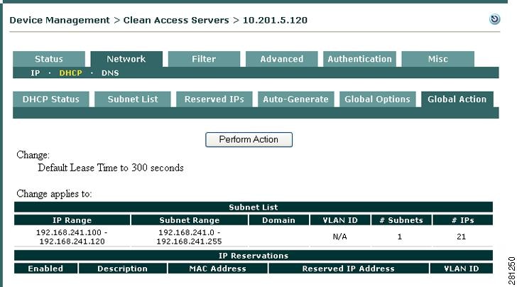
5.
Figure 5-31 Example Global Action