Feedback
Table Of Contents
Installing IDS-4235 and IDS-4250
Introducing IDS-4235 and IDS-4250
Front-Panel Features and Indicators
Back-Panel Features and Indicators
Installing Spare Hard-Disk Drives
Installing IDS-4235 and IDS-4250
Installing and Removing the Bezel
Disconnecting the XL Card Fiber Ports
Removing and Replacing the SCSI Hard-Disk Drive
Removing the SCSI Hard-Disk Drive
Replacing the SCSI Hard-Disk Drive
Recommended Tools and Supplies
Installing the Slide Assemblies
Installing the Appliance in the Rack
Installing the Cable-Management Arm
Recommended Tools and Supplies
Installing the Slide Assemblies in the Rack
Installing IDS-4235 and IDS-4250
This chapter describes IDS-4235 and IDS-4250 and how to install them. It also describes the accessories and how to install them.
Note
IDS-4235 and IDS-4250 are being replaced by IPS-4240 and IPS-4255. They do not ship with IPS 5.0 installed. You must upgrade them to IPS 5.0.
This chapter contains the following sections:
•
•
•
•
•
•
Introducing IDS-4235 and IDS-4250
You can deploy IDS-4235 at 250 Mbps to provide protection in switched environments and on multiple T3 subnets. With the support of 10/100/1000 interfaces you can also deploy it on partially utilized gigabit links. The sensing interface and the command and control interface are both 10/100/1000BASE-TX. You can install the 4FE card to provide an additional four sensing interfaces. You can also install the optional 10/100/1000BASE-TX adapter card, which allows additional options for inline functionality beyond the 4FE card. For the procedure for installing optional PCI cards, see Installing Optional PCI Cards.
Note
IDS-4250 supports a 500-Mbps speed and can be used to protect gigabit subnets and traffic traversing switches that are being used to aggregate traffic from numerous subnets. The sensing interface and the command and control interface are both 10/100/1000BASE-TX. The optional interface is 1000BASE-SX (fiber). You can now install a second SX card in the IDS-4250. In addition, you can upgrade IDS-4250 to full line-rate gigabit performance with the IDS Accelerator (XL) card. You can also install the 4FE card to provide an additional four sensing interfaces. There is also an optional 10/100/1000TX adapter card that allows additional options for inline functionality beyond the 4FE card. For the procedure for installing optional PCI cards, see Installing Optional PCI Cards.
Note
Or you can order IDS-4250-XL with the XL card already installed. At 1 Gbps, IDS 4250-XL provides customized hardware acceleration to protect fully saturated gigabit links as well as multiple partially utilized gigabit subnets.
Note
Front-Panel Features and Indicators
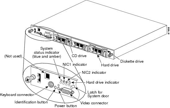
Figure 4-1 shows the controls, indicators, and connectors located behind the bezel on the front panel of IDS-4235 and IDS-4250.
Figure 4-1 Front-Panel Features and Indicators
The power button controls the AC power input to the power supplies of IDS-4235 and IDS-4250.
You can use the identification buttons on the front and back panels to locate a particular IDS-4235 or IDS-4250 in a rack. When you push one of these buttons, the blue system status indicator on the front and back blinks until you push one of the buttons again.
The front panel also has a video connector for connecting a monitor and a PS/2 connector for connecting a keyboard.
Table 4-1 describes the appearance of the front panel indicators for IDS-4235 and IDS-4250.
Table 4-1 Front-Panel Indicators
Blue and amber system status indicator

The blue system status indicator lights up during normal system operation. The amber system status indicator flashes when the system needs attention due to a problem with power supplies, fans, system temperature, or hard drives.1
NIC1 and NIC2 link and activity indicators

The link and activity indicators for the two integrated NICs light up when the NICs are in use.
Hard-disk drive indicator

The green hard-disk drive activity indicator flashes when the hard-disk drive is in use.
Power button

The power button lights up when the system power is on.
1 If the system is connected to AC power and an error has been detected, the amber system status indicator will flash regardless of whether the system has been powered on
Back-Panel Features and Indicators
Figure 4-2 shows the controls, indicators, and connectors located on the back panel of the IDS-4235 or IDS-4250.
Note
Figure 4-2 Back-Panel Features and Indicators
Specifications
Table 4-2 lists IDS-423 and IDS-4250 specifications.
Installing Spare Hard-Disk Drives
Do not install a second hard-disk drive in IDS-4235 or IDS-4250. The spare hard-disk drives are meant to replace the original hard-disk drives and are not meant to be used in conjunction with the original hard-disk drive. If you install two hard-disk drives in IDS-4235 or IDS-4250, they may not recognize the recover command used to recover the application partition.
If the original hard-disk drive becomes unusable, remove the hard-disk drive and insert the replacement hard-disk drive. For the procedure, see Removing and Replacing the SCSI Hard-Disk Drive.
The replacement hard-disk drive is shipped blank from the factory. You must reimage it. For the procedure, refer to Upgrading, Downgrading, and Installing System Images.
Upgrading the BIOS
If the BIOS version is earlier than A04 on IDS-4235 or IDS-4250, you must upgrade the BIOS before you install Cisco IPS 5.0 software.
Caution
Check the BIOS version before performing the following procedure. Reboot the appliance and watch for the BIOS version number. The following example shows BIOS version A03:
Phoenix ROM BIOS PLUS Version 1.10 A03Cisco Systems IDS-4235/4250www.cisco.comTesting memory. Please wait.If the version is A01, A02, or A03, you must upgrade the BIOS to version A04.
To create and boot the IDS-4235 and IDS-4250 BIOS upgrade diskette, follow these steps:
Step 1
You can find the file in the /BIOS directory on the recovery/upgrade CD, or you can download it from Cisco.com. For the procedure for downloading Cisco IPS software from the Software Center on Cisco.com, see Obtaining Cisco IPS Software.
Step 2
Step 3
Step 4
Caution
Caution
Step 5
Step 6
Using the TCP Reset Interface
IDS-4250-XL has a TCP reset interface—INT0. IDS-4250-XL has a specific TCP reset interface because it cannot send TCP resets on its sensing ports.
If you have reset problems with IDS-4250-XL, try the following:
•
•
Note
•
Installing IDS-4235 and IDS-4250
Warning
Caution
To install IDS-4235 and IDS-4250 on the network, follow these steps:
Step 1
Step 2
Step 3
Table 4-3 Terminal Settings
Bits per second
9600
Data bits
8
Parity
None
Stop bits
1
Flow control
Hardware or RTS/CTS
Caution
Note
Step 4
IDS-4225 and IDS-4250 have the following interfaces:
•
•
•
•
•
•
Step 5
Caution
Step 6
For the procedure, see Initializing the Sensor.
Step 7
For the procedure, see Obtaining Cisco IPS Software.
You are now ready to configure intrusion prevention on the appliance.
For More Information
•
•
–
–
Installing the Accessories
This section describes the contents of the IDS-4235 and IDS-4250 accessories package and how to install the accessories. It contains these topics:
•
•
•
•
Accessories Package Contents
The following items are shipped in the accessories package for IDS-4235 and IDS-4250:
•
•
•
•
•
•
•
–
–
–
Note
–
Installing and Removing the Bezel
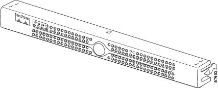
Figure 4-3 shows the Cisco bezel that you can install on IDS-4235 and IDS-4250.
Figure 4-3 Cisco Bezel
To install and remove the bezel on IDS-4235 and IDS-4250, follow these steps:
Step 1
a.
b.
Step 2
Installing the Power Supply
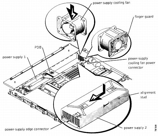
You can install a second, redundant power supply and power-supply cooling fan (part number IDS-PWR=) in IDS-4235 and IDS-4250.
Caution
To install a power supply and fan, follow these steps:
Step 1
Step 2
sensor# reset powerdownWait for the power down message before continuing with Step 3.
Note
Step 3
Step 4
Step 5
For more information, see Working in an ESD Environment.
Step 6
a.
b.
c.
d.
Step 7
Note
Step 8
Step 9
WarningStep 10
Figure 4-4 Power Supply and Power-Supply Cooling Fan
Step 11
a.
b.
c.
Step 12
Installing Optional PCI Cards
You can install the following optional PCI cards in IDS-4235 and IDS-4250. The optional PCI cards provide additional sensing interfaces.
•
You can install one or two SX cards in the IDS-4250.
•
You can install the TX card in the upper PCI slot in the IDS-4250.
•
You can install the XL card in the upper PCI slot in the IDS-4250. The XL card accelerates the performance of IDS-4250 up to 1 Gbps. You can use an MTRJ cable (part number CAB-MTRJ-SC-MM-3M=) to connect the fiber port on the XL card to the switch on the network. You can order this cable when you order the XL card.
For information about disconnecting the fiber ports the first time you boot IDS-4250 after upgrading with the XL card, see Disconnecting the XL Card Fiber Ports.
•
You can install the 4FE card in the lower PCI slot in the IDS-4235 and IDS-4250.
Caution
Note
To install the PCI card, follow these steps:
Step 1
Step 2
sensor# reset powerdownWait for the power down message before continuing with Step 3.
Note
Step 3
Step 4
Step 5
For more information, see Working in an ESD Environment.
Step 6
a.
b.
c.
d.
Step 7
a.
b.
Step 8
Caution
Step 9
Step 10
a.
b.
c.
Step 11
Note
Step 12
Caution
Step 13
•
•
•
•
For the CLI procedure, refer to Configuring Interfaces. For the IDM procedure, refer to Configuring Interfaces.
Disconnecting the XL Card Fiber Ports
When you upgrade IDS-4250-TX and IDS-4250-SX with the XL card, they may not boot up the first time if the fiber ports are connected. Disconnect the fiber ports before you boot them. After they start for the first time, the firmware version is upgraded and the problem is not seen again.
Note
To allow IDS-4250 to reboot after installing the XL card, follow these steps:
Step 1
Step 2
sensor# reset powerdownWait for the power down message before continuing with Step 3.
Note
Step 3
Step 4
Step 5
Wait until IDS-4250 has completed bootup and you see a login prompt.
Step 6
During the startup of the IPS applications, the XL card is upgraded to the latest firmware.
Removing and Replacing the SCSI Hard-Disk Drive
IDS-4235 and IDS-4250 has a removable SCSI hard-disk drive. You can replace the hard-disk drive in case of drive failure. Or you can order a spare drive (part number IDS-SCSI=), apply your configuration, and ship the drive to a remote site. The administrator at the remote site can then install the configured drive.
Caution
Caution
Figure 4-5 shows the SCSI hard-disk drive indicators.
Figure 4-5 SCSI Hard-Disk Drive
When you have installed the new hard-disk drive, you must reimage it with the recovery/upgrade CD. For the procedure, refer Using the Recovery/Upgrade CD.
This section contains the following topics:
•
•
Removing the SCSI Hard-Disk Drive
To remove the SCSI hard-disk drive, follow these steps:
Step 1
Step 2
sensor# reset powerdownWait for the power down message before continuing with Step 3.
Note
Step 3
Step 4
For the procedure, see Installing and Removing the Bezel.
Step 5
Step 6
Replacing the SCSI Hard-Disk Drive
To replace the SCSI hard-disk drive, follow these steps:
Step 1
Step 2
sensor# reset powerdownWait for the power down message before continuing with Step 3.
Note
Step 3
Step 4
For the procedure, see Installing and Removing the Bezel.
Step 5
Step 6
Step 7
Step 8
Step 9
For the procedure, see Installing and Removing the Bezel.
Note
Four-Post Rack Installation
You can install the appliance in a four-post rack (part number IDS-RAIL-4=).
Caution
This section contains the following topics:
•
•
•
•
Recommended Tools and Supplies
You need these tools and supplies to install the appliance in a four-post rack cabinet:
•
•
Rack Kit Contents
The four-post rack kit includes the following items:
•
•
•
•
•
•
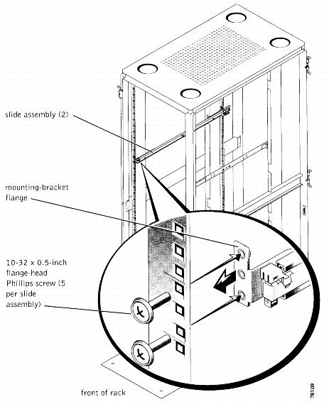
Installing the Slide Assemblies
The rack is measured in rack units (RU). An RU is equal to 44 mm or 1.75 inches.
To install the slide assemblies, follow these steps:
Step 1
Step 2
Note
Step 3
Note
Step 4
Note
Step 5
Figure 4-6 Slide Assemblies
Step 6
Step 7
Step 8
Step 9
Installing the Appliance in the Rack
If you are installing more than one appliance, install the first appliance in the lowest available position in the rack.
Caution
To install the appliance in the rack, follow these steps:
Step 1
Caution
Step 2
Step 3
Step 4
Step 5
Step 6
Step 7
The appliance release latch moves forward and then snaps back as the shoulder screw passes into the front slot.
Note
Figure 4-7 Installing the Appliance in the Rack
Step 8
Step 9
Installing the Cable-Management Arm
You can install the cable-management arm on the right or left of the rack cabinet. This procedure describes installing the cable-management arm in the right side of the rack cabinet, as viewed from the back.
Tip
To install the cable-management arm, follow these steps:
Step 1
Step 2
Note
Step 3
Note
Step 4
Note
Note
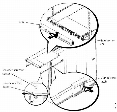
Figure 4-8 Cable-Management Arm
Step 5
Step 6
The wire cover swings open to enable cables to be routed within the arm.
Step 7
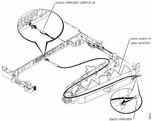
Figure 4-9 Installing the Cable-Management Arm
Step 8
Note
Step 9
Step 10
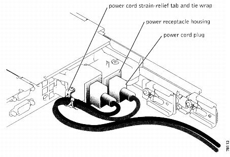
Figure 4-10 Power Cord Strain Relief
Routing the Cables
To route the cables, follow these steps:
Step 1
For details on the cable connections, see Installing IDS-4235 and IDS-4250.
Step 2
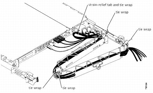
Note
Figure 4-11 Routing Cables
Step 3
a.
b.
c.
Note
Step 4
Step 5
Step 6
Note
Warning
Two-Post Rack Installation
You can install the two-post rack (part number IDS-RAIL-2=) in a center-mount or flush-mount configuration. The two-post kit incorporates slide assemblies that enable the appliance to be pulled out of the rack for servicing.
You must properly secure the two-post, open frame relay rack to the floor, the ceiling or upper wall, and where applicable, to adjacent racks, using floor and wall fasteners and bracing specified or approved by the rack manufacturer.
This section contains these topics:
•
•
Recommended Tools and Supplies
You need the following tools and supplies to install the appliance in a two-post, open-frame relay rack:
•
•
•
Rack Kit Contents
The two-post rack kit includes:
•
•
•
•
•
•
Marking the Rack
You must allow 1 RU (44 mm or 1.75 inches) of vertical space for each appliance you install in the two-post rack.
To mark the rack, follow these steps:
Step 1
Note
Step 2
Note
Installing the Slide Assemblies in the Rack
You can install the slide assemblies in a two-post, open-frame relay rack having either universal-hole spacing or wide-hole spacing. You can install the 1-RU slide assemblies in either a flush-mount or center-mount configuration.
This section contains these topics:
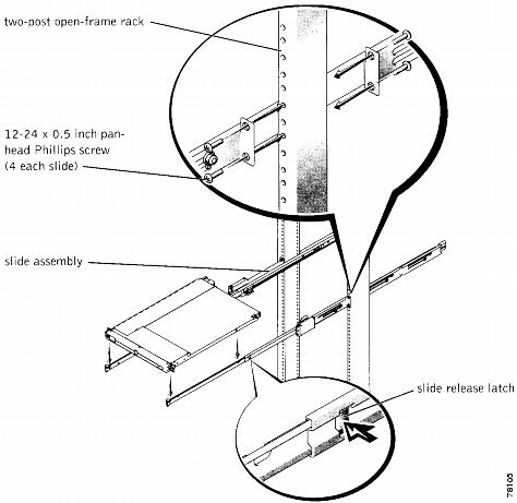
Center-Mount Installation
The two-post rack kit is shipped with brackets configured for center-mount installation.
To install the center-mount brackets, follow these steps:
Step 1
Step 2
Step 3
Figure 4-12 Slide Assemblies for Center-Mount Configuration
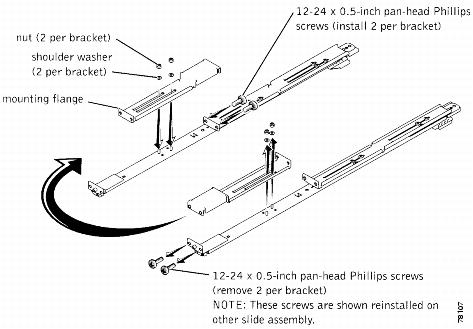
Flush-Mount Installation
To install the flush-mount brackets, follow these steps:
Step 1
Note
Step 2
Step 3
Step 4
Step 5
Step 6
The joined bracket becomes the new extended rear bracket.
Figure 4-13 Rotating the Front-Mounting Bracket for Flush-Mount Installation
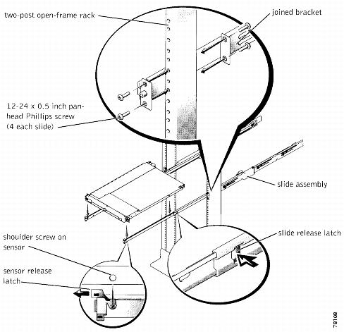
Step 7
Step 8
Step 9
Step 10
Step 11
Figure 4-14 Installing the Slide Assemblies for Flush-Mount Configuration