Feedback Feedback
|
Table Of Contents
Cisco IAD2420 Series Integrated Access Devices
Documents, Equipment, and Tools
Cisco IAD2420 Series Documentation
Cisco IOS Software Documentation
Items Included with Cisco IAD2420 Series IAD
Connecting LAN, Serial Port, Administrative Access, and Power Cables
Connecting the WAN, Uplink, and User-Side Cables
Set the Ethernet Port IP Address
Configure a T1-WAN Port for a WAN Connection
Configure an ATM Interface (T1-WAN Port and ADSL/SHDSL Port)
Verify and Save Your Configuration
Obtaining Technical Assistance
Quick Start Guide
Cisco IAD2420 Series Integrated Access Devices
1 Documents, Equipment, and Tools
User Documentation
All of the documents described here are available online and on the documentation CD-ROM that you received with your Cisco Integrated Access Device (IAD). To be sure of obtaining the latest information, you should access the online documentation.
To print a document in its original page format, access the online document, and click on the PDF icon.
You can also order printed copies of some documents. See the "Obtaining Documentation" section.
To access online user documentation (PDF and HTML formats):
From Cisco.com at http://www.cisco.com, under Service & Support, select Technical Documents and select Cisco Product Documentation.
To access user documentation on the Documentation CD-ROM (HTML format only):
On the Documentation CD-ROM, select Cisco Product Documentation.
Paths to specific documents are provided below, starting at Cisco Product Documentation.
Tip
To navigate up to the next higher level in the documentation hierarchy, click on CONTENTS in the navigation bar at the top of each page.
Cisco IAD2420 Series Documentation
Regulatory Compliance and Safety Information
The Regulatory Compliance and Safety Information document provides essential safety information applicable to your Cisco IAD. This document contains multiple-language translations of the safety warnings applicable to the Cisco IAD2400 series IADs.
You can access this document at: Cisco Product Documentation > Access Servers and Access Routers > Integrated Access Devices > Cisco IAD2420 Series IADs > Cisco IAD2420 Series Regulatory Compliance and Safety Information
Hardware Installation Guide
The hardware installation guide provides additional detailed description, installation, and cabling information.
You can access this document at: Cisco Product Documentation > Access Servers and Access Routers > Integrated Access Devices > Cisco IAD2420 Series IADs > Cisco IAD2420 Series Integrated Access Devices Hardware Installation Guide
Software Configuration Guide
The software configuration guide provides additional detailed configuration information specific to the Cisco IAD2420 series IADs.
You can access this document at: Cisco Product Documentation > Access Servers and Access Routers > Integrated Access Devices > Cisco IAD2420 Series IADs > Cisco IAD2420 Series Integrated Access Devices Software Configuration Guide
Release Notes
Cisco IOS release notes for the Cisco IAD2420 series IADs provide up-to-date information about specific Cisco IOS software releases used on Cisco IAD2420 series IADs.
You can access these documents at: Cisco Product Documentation > Access Servers and Access Routers > Integrated Access Devices > Cisco IAD2420 Series IADs > Cisco IOS Release Notes
Cisco IOS Software Documentation
Master Index to Software Documentation
The master index provides links to topics and commands for specific Cisco IOS software releases.
You can access master indexes at: Cisco Product Documentation > Cisco IOS Software Configuration > Cisco IOS Software Release you are using > Master Index for Cisco IOS Software Release you are using
Configuration Guides
The Cisco IOS software configuration guides provide detailed configuration procedures and examples.
You can access these documents at: Cisco Product Documentation > Cisco IOS Software Configuration > Cisco IOS Software Release you are using > Configuration Guides and Command References > Configuration guide for your application
Command References
The Cisco IOS software command references provide detailed information about each configuration command.
You can access these documents at: Cisco Product Documentation > Cisco IOS Software Configuration > Cisco IOS Software Release you are using > Configuration Guides and Command References > Command reference for your application
New Feature Documentation
New feature documentation contains information about new configuration commands introduced in specific Cisco IOS releases.
You can access these documents at: Cisco Product Documentation > Cisco IOS Software Configuration > Cisco IOS Software Release you are using > New Feature Documentation
If you have an account on Cisco.com, you can get updated information about platform support for features by accessing Cisco Feature Navigator at the following URL:
http://www.cisco.com/go.fn
Release Notes
Cisco IOS release notes for all platforms provide up-to-date information about specific Cisco IOS software releases.
You can access these documents at: Cisco Product Documentation > Cisco IOS Software Configuration > Cisco IOS Software Release you are using > Release Notes
Supporting Documents and Related Documentation
You can access additional information about specific Cisco IOS software releases, platforms, and applications at: Cisco Product Documentation > Cisco IOS Software Configuration > Cisco IOS Software Release you are using > Supporting Documents or Related Documentation
Items Included with Cisco IAD2420 Series IAD
•
•
•
•
•
•
•
Items Not Included
Individual items in this list may be required for your particular application:
•
•
•
•
•
•
•
•
•
•
2 Install Chassis
Safety Information
Warning
Chassis Installation Methods
You can set the chassis on a desktop, install it in a rack, or mount it on a wall. See the applicable instructions following:
Warning
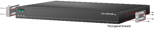
Rack-Mounting the Chassis
Step 1
Note
Step 2
Figure 1 19-Inch Rack Mounting With Front Panel Forward
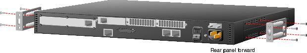
Figure 2 19-Inch Rack Mounting With Rear Panel Forward
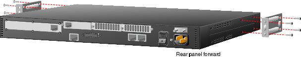
Figure 3 Telco 19-Inch Rack Mounting With Rear Panel Forward
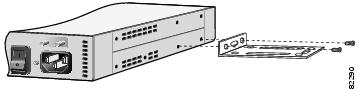
Wall-Mounting the Chassis
Step 1
Figure 4 Attaching the Brackets for Wall-Mounting
Step 2
•
•
•
Chassis Ground Connection
You must connect the chassis to a reliable earth ground using the ground lug (provided) and size AWG 6 (13 mm2) wire.
Step 1
Step 2
Step 3
Step 4
Figure 5 Required Ground Connection on a Cisco IAD2420 Series Chassis
3 Connect Cables
Warning
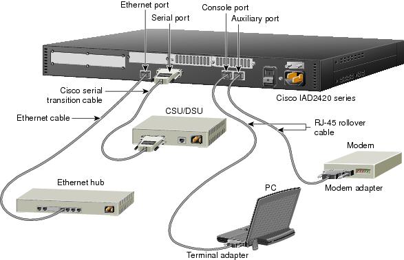
Connecting LAN, Serial Port, Administrative Access, and Power Cables
These cables and connections are described in Table 1 and Figure 6.
Table 1 LAN, Serial Port, Administrative Access, and Power Cable Selection
Ethernet
Yellow
Ethernet hub
Straight-through Ethernet (not included).
Console
Light blue
PC or ASCII terminal communication (COM) port
RJ-45-to-RJ-45 rollover cable (included) and terminal adapter (included).
Auxiliary
Black
Modem for remote access
RJ-45-to-RJ-45 rollover cable and a modem adapter (included).
Serial
60-pin D-sub
CSU/DSU and serial network or equipment
Cisco serial transition cable (not included) that matches the signaling protocol (EIA/TIA-232, EIA/TIA-449, V.35, X.21, or EIA-530) and the serial port operating mode (DTE or DCE).
See the Cisco IAD2420 Series Integrated Access Devices Hardware Installation Guide for information about selecting these cables. You can access this document at the location described in the "User Documentation" section of this quick start guide.
Power
Power
100-240 VAC, 50-60 Hz
Grounding power cord (included).
Figure 6 LAN, Serial Port, Administrative Access, and Power Connections
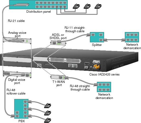
Connecting the WAN, Uplink, and User-Side Cables
These cables and connections are described in Table 2 and Figure 7.
Figure 7 WAN, Uplink, and User-Side Connections
4 Power On the Cisco IAD
Checklist for Power-On
You are ready to power on the Cisco IAD if it meets these requirements:
•
•
Power-On Procedure
Perform this procedure to power on your Cisco IAD and verify that it goes through its initialization and self-test. When this is finished, the Cisco IAD is ready to configure.
Step 1
Step 2
The green LED next to the auxiliary port should go on and the fan should operate. If this does not happen, see the power-on procedure in the Cisco IAD2420 Series Integrated Access Device Hardware Installation Guide.
The following message is displayed at the end of the boot-up messages.
--- System Configuration Dialog ---Would you like to enter the initial configuration dialog? [yes/no]:Step 3
Would you like to enter the initial configuration dialog? [yes/no]: noWould you like to terminate autoinstall? [yes]Step 4
Several messages are displayed, ending with a line similar to the following:
...Copyright (c) 1986-2001 by cisco Systems, Inc.Compiled <date> <time> by <person>Step 5
...flashfs[4]: Initialization complete.Router>Step 6
Router> enableRouter#Step 7
5 Perform Initial Configuration
This section shows how to prepare the system to perform basic communication functions through its Ethernet and WAN interfaces.
Perform the following initial configuration procedures, as applicable:
•
•
•
•
Get Your Network Information
Gather the following information, as applicable, before you begin the configuration process:
•
•
•
Set the Ethernet Port IP Address
Complete this procedure to set an IP address for the Ethernet port. After the Ethernet port has an IP address, you can configure the Cisco IAD remotely through a Telnet connection.
Configure a T1-WAN Port for a WAN Connection
The T1-WAN port supports balanced T1 per ANSI T1.403 and has a built-in CSU/DSU (Cisco IAD2421 IADs only).
To configure the basic T1 controller settings to support Asynchronous Transfer Mode (ATM), Point-to-Point Protocol (PPP), high-level data link control (HDLC), or Frame Relay (FR), complete the following steps beginning in global configuration mode:
For additional information about configuring specific features, see the following references:
•
You can access master indexes at: Cisco Product Documentation > Cisco IOS Software Configuration > Cisco IOS Software Release you are using > Master Index for Cisco IOS Software Release you are using
•
You can access this document at: Cisco Product Documentation > Access Servers and Access Routers > Integrated Access Devices > Cisco IAD2420 Series IADs > Cisco IAD2420 Series Integrated Access Devices Software Configuration Guide
Configure an ATM Interface (T1-WAN Port and ADSL/SHDSL Port)
If your Cisco IAD has an ADSL WAN port, a default ATM configuration is automatically enabled when you power up the Cisco IAD.
If your Cisco IAD has an SHDSL or T1-WAN port, a default ATM configuration is automatically enabled when you enter the mode atm controller command.
The default ATM configuration has the following operating parameters:
•
–
•
–
–
–
–
–
To configure the ATM interface parameters for your application, you need the following information:
•
•
•
•
•
To enter an ATM configuration, complete the following steps beginning in global configuration mode:
Step 1
Router(config)# controller t1 0
For an SHDSL port:Router(config)# controller shdsl 0
For an ADSL port:Go to step 6.
Enters controller configuration mode and the controller number.
Step 2
Router(config-ctrl)# mode atm
Enables ATM encapsulation and creates logical ATM interface 0. Controller framing is automatically set to Extended SuperFrame (ESF). The linecode is automatically set to B8ZS.
Step 3
Router(config-ctrl)# annex {a | b}
Specifies the regional operating parameters. Enter a for North America and b for Europe. The default is a.
Step 4
Router(config-ctrl)# line-rate {auto | rate}
Specifies the DSL line rate for the SHDSL port. The range is 72 to 2312 kbps. The default is auto (negotiated between the SHDSL port and the DSLAM)
Note
Step 5
Router(config-ctrl)# exit
Exits from controller configuration mode.
Step 6
Router(config)# interface atm 0
Enters ATM configuration mode for interface ATM 0.
Step 7
Router(config-if)# ip-address IP-address
(Optional) Assigns an IP address to the ADSL or SHDSL ATM interface.
Step 8
Router(config-if)# atm uni-version version-number
(Optional) Specifies an ATM user network interface (UNI) version number.
Step 9
Router(config-if)# atm ilmi-keepalive [seconds]
(Optional) Enables Integrated Local Management Interface (ILMI) keepalives.
If you enable ILMI keepalives without specifying the seconds, the default time interval is 3 seconds.
Step 10
Router(config-if)# pvc [name] vpi/vci
Enters atm-virtual-circuit (interface-atm-vc) configuration mode, and configure a new ATM PVC by assigning a name (optional) and VPI/VCI numbers.
The default traffic shaping is UBR; the default encapsulation is AAL5+LLC/SNAP.
Step 11
Router(config-if-vc)# protocol ip IP-address
(Optional) Enables IP connectivity and create a point-to-point IP address for the VC.
Step 12
Router(config-if-vc)# vbr-rt peak-rate average-rate burst
(Optional) Configures the PVC for real-time variable bit rate (VBR) traffic shaping.
•
For SHDSL ports, set the peak rate for the trained line rate minus 8 kbps.
•
•
Step 13
Router(config-if-vc)# encapsulation {aal1 | aal2 | aal5ciscoppp | aal5mux | aal5nlpid | aal5snap}
(Optional) Configures the ATM adaptation layer (AAL) and encapsulation type to match those of the service provider.
•
•
•
•
•
•
Step 14
Router(config-if-vc)# exit
Exits from interface-ATM-VC configuration mode.
Step 15
Repeat steps 10 through 14 for each additional ATM PVC to be configured.
Configures the remaining ATM PVCs.
Step 16
Router(config-if)# dsl operating-mode {ansi-dmt | auto itu-dmt | splitterless}
For an SHDSL port or a T1-WAN port:Go to step 17.
Configures the ADSL interface to operate in a specified mode:
•
•
•
•
Step 17
Router(config-if)# no shutdown
Activates the ATM interface.
Step 18
Router(config-if)# exit
Exits from ATM interface configuration mode.
Step 19
Router(config)# exit
Exits from global configuration mode.
Step 20
Router# show interface atm 0
Verifies the ATM interface configuration.
Verify and Save Your Configuration
To verify the configuration and save it in NVRAM so that the configuration remains in effect if the Cisco IAD is restarted, enter the following commands:
Where to Go Next
For additional specialized configuration procedures, refer to the appropriate Cisco IOS software configuration documentation, available on the Documentation CD-ROM and on Cisco.com:
Tip
For detailed configuration information specific to the Cisco IAD2420 series integrated access device:
Cisco IAD2420 Series Integrated Access Devices Software Configuration Guide
You can access this document at: Cisco Product Documentation > Access Servers and Access Routers > Integrated Access Devices > Cisco IAD2420 Series IADs > Cisco IAD2420 Series Software Configuration Guide
For detailed configuration information for specific features:
Configuration Guides and Command References for the Cisco IOS software release installed on your Cisco router.
You can access these documents at: Cisco Product Documentation > Cisco IOS Software Configuration > Cisco IOS Software Release you are using > Configuration Guides and Command References
For new features associated with a specific software release:
New feature documentation for the Cisco IOS software release installed on your Cisco router.
You can access these documents at: Cisco Product Documentation > Cisco IOS Software Configuration > Cisco IOS Software Release you are using > New Feature Documentation
Cisco Feature Navigator
If you have an account on Cisco.com, you can get updated information about platform support for features by accessing Feature Navigator at the following URL:
http://www.cisco.com/go.fn
6 Obtaining Documentation
These sections explain how to obtain documentation from Cisco Systems.
World Wide Web
You can access the most current Cisco documentation on the World Wide Web at this URL:
Translated documentation is available at this URL:
http://www.cisco.com/public/countries_languages.shtml
Documentation CD-ROM
Cisco documentation and additional literature are available in a Cisco Documentation CD-ROM package, which is shipped with your product. The Documentation CD-ROM is updated monthly and may be more current than printed documentation. The CD-ROM package is available as a single unit or through an annual subscription.
Ordering Documentation
You can order Cisco documentation in these ways:
•
http://www.cisco.com/public/ordsum.html
•
http://www.cisco.com/go/subscription
•
Documentation Feedback
You can submit comments electronically on Cisco.com. In the Cisco Documentation home page, click the Fax or Email option in the "Leave Feedback" section at the bottom of the page.
You can e-mail your comments to bug-doc@cisco.com.
You can submit your comments by mail by using the response card behind the front cover of your document or by writing to the following address:
Cisco Systems
Attn: Document Resource Connection
170 West Tasman Drive
San Jose, CA 95134-9883We appreciate your comments.
7 Obtaining Technical Assistance
Cisco provides Cisco.com as a starting point for all technical assistance. Customers and partners can obtain online documentation, troubleshooting tips, and sample configurations from online tools by using the Cisco Technical Assistance Center (TAC) Web Site. Cisco.com registered users have complete access to the technical support resources on the Cisco TAC Web Site.
Cisco.com
Cisco.com is the foundation of a suite of interactive, networked services that provides immediate, open access to Cisco information, networking solutions, services, programs, and resources at any time, from anywhere in the world.
Cisco.com is a highly integrated Internet application and a powerful, easy-to-use tool that provides a broad range of features and services to help you with these tasks:
•
•
•
•
•
If you want to obtain customized information and service, you can self-register on Cisco.com. To access Cisco.com, go to this URL:
Technical Assistance Center
The Cisco Technical Assistance Center (TAC) is available to all customers who need technical assistance with a Cisco product, technology, or solution. Two levels of support are available: the Cisco TAC Web Site and the Cisco TAC Escalation Center.
Cisco TAC inquiries are categorized according to the urgency of the issue:
•
•
•
•
The Cisco TAC resource that you choose is based on the priority of the problem and the conditions of service contracts, when applicable.
Cisco TAC Web Site
You can use the Cisco TAC Web Site to resolve P3 and P4 issues yourself, saving both cost and time. The site provides around-the-clock access to online tools, knowledge bases, and software. To access the Cisco TAC Web Site, go to this URL:
All customers, partners, and resellers who have a valid Cisco service contract have complete access to the technical support resources on the Cisco TAC Web Site. The Cisco TAC Web Site requires a Cisco.com login ID and password. If you have a valid service contract but do not have a login ID or password, go to this URL to register:
http://www.cisco.com/register/
If you are a Cisco.com registered user, and you cannot resolve your technical issues by using the Cisco TAC Web Site, you can open a case online by using the TAC Case Open tool at this URL:
http://www.cisco.com/tac/caseopen
If you have Internet access, we recommend that you open P3 and P4 cases through the Cisco TAC Web Site.
Cisco TAC Escalation Center
The Cisco TAC Escalation Center addresses priority level 1 or priority level 2 issues. These classifications are assigned when severe network degradation significantly impacts business operations. When you contact the TAC Escalation Center with a P1 or P2 problem, a Cisco TAC engineer automatically opens a case.
To obtain a directory of toll-free Cisco TAC telephone numbers for your country, go to this URL:
http://www.cisco.com/warp/public/687/Directory/DirTAC.shtml
Before calling, please check with your network operations center to determine the level of Cisco support services to which your company is entitled: for example, SMARTnet, SMARTnet Onsite, or Network Supported Accounts (NSA). When you call the center, please have available your service agreement number and your product serial number.