Feedback
Table Of Contents
Replacing Cisco AS5850 Components
Replacing a DC Power Entry Module
Verifying and Troubleshooting the Installation
Replacing an AC-Input Power Module
Removing and Replacing a Power Module
Installing a Flash Memory Card
Verifying and Troubleshooting the Installation
Troubleshooting the Cisco AS5850
Maintenance
This chapter provides hardware replacement, system debugging, and troubleshooting procedures.
Replacing Cisco AS5850 Components
This section provides detailed replacement procedures for Cisco AS5850 field-replaceable units (FRUs) and covers the following areas:
•
Powering Off the Cisco AS5850
•
•
•
Note
Powering Off the Cisco AS5850
Some procedures in this section require that you power off the gateway. Refer to this section when appropriate.
Powering off the gateway involves removing power from the following components:
•
•
Warning
Step 1
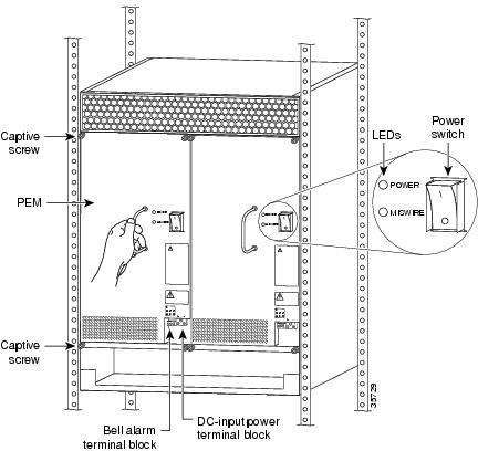
Figure 4-1 Power Switches on the PEMFs
Step 2
Replacing a DC Power Entry Module
This section explains how to remove and replace the power entry module/filters (PEMFs) in the chassis.
Tools and Parts Required
You need the following tools and parts:
•
•
•
•
•
•
Removing a PEMF
This section explains how to remove and replace the PEMFs in the chassis.
Warning
Warning
Caution
Note
The following procedure for hot-swapping a PEMF assumes that you are not using the optional AC-input power shelf, and that each PEMF in your server is connected to a separate DC power source. If you are removing and replacing a PEMF in an AC-configured system, you must perform the replacement during a scheduled maintenance time and power off the entire system.
Warning
To remove a PEMF, complete the following steps.
Step 1
Step 2
Step 3
Caution
Figure 4-2 PEMF Front Panel
Step 4
Step 5
Step 6
Step 7
This completes the PEMF removal process. Continue with the "Replacing the Power Entry Module" section.
Replacing the Power Entry Module
To install a new PEMF, complete the following steps. (Refer to Figure 4-2 to locate the PEMFs in the server.)
Step 1
Step 2
Step 3
Step 4
This completes the procedure for replacing a PEMF in the server. To connect the PEMF power cables and power on the PEMF, continue with the "Connecting to Your DC Power Source" section. Or, if you are connecting to an AC power source, continue with the "Connecting to an AC Power Source" section.
Connecting to Your DC Power Source
If your site has access to a DC power source, you need to provide your own DC power cables. In the United States you need to use 6 AWG stranded or solid copper wire; elsewhere, use 16 mm2 solid or 10 mm2 stranded copper wire.
To reconnect the PEMF to your DC-input power source, complete the following steps.
Step 1
Step 2
Step 3
Step 4
Step 5
Note
Step 6
Step 7
This completes the procedure for replacing a PEMF and connecting to your DC power source. Continue with the "Verifying and Troubleshooting the Installation" section for installation troubleshooting tips.
Connecting to an AC Power Source
If you are using the optional 2400W AC-input power shelf, you cannot remove and replace a PEMF while the system is powered on.
Caution
Verifying and Troubleshooting the Installation
To complete installation, verify that the PEMF LEDs operate properly and that you have wired the DC-input connections correctly. Each PEMF contains two LEDs on the front panel: POWER and MISWIRE. (See Figure 4-2.)
•
If neither the POWER nor the MISWIRE LED is on, check the voltage at the DC-input terminal block. If the voltage reading falls between -40 and -60 VDC, replace the PEMF.
•
If the MISWIRE LED is on, the two DC conductors entering the PEMF DC-input terminal block are reversed. Power off power at the source and reverse the connections.
This completes the procedures for installing and troubleshooting a PEMF. To verify that the PEMF is properly installed, refer to the Cisco AS5850 Universal Gateway Hardware Installation Guide.
Replacing an AC-Input Power Module
The 2400W AC-input power shelf is an optional component of the Cisco AS5850, and converts AC-input power into DC-output power for the DC-powered Cisco AS5850. The power shelf contains three loadsharing 2400W AC-input power modules—two required for normal functioning and one for redundancy.
This section explains how to remove and replace an individual power module in the power shelf.
Tools and Parts Required
You need the following tools and parts:
•
•
•
Removing and Replacing a Power Module
Use the following procedure to replace a faulty power module. The AC-input power shelf is configured with three 110 VAC power supplies. You can remove or replace one of the power supplies without affecting system operation. When power is removed from one supply, the redundant power feature causes the other two power supplies to ramp up to full power and maintain uninterrupted system operation.
To remove a power module, follow these steps.
Caution
Step 1
Step 2
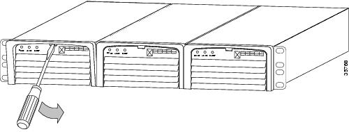
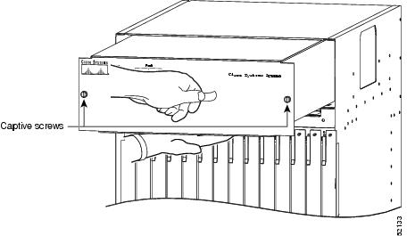
Figure 4-3 Releasing the Lock on a Power Module
Step 3
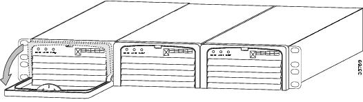
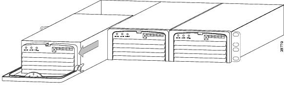
Figure 4-4 Removing and Replacing a Power Module
Step 4
To replace the power module, follow these steps.
Step 1
Step 2
This completes the power-module replacement procedure.
Replacing a Server Card
The procedure for removing all trunk, port, or route switch controller cards is essentially the same, and is provided in the Cisco AS5850 Universal Gateway Card Guide. This section describes OIR and compact Flash procedures specific to the RSC card.
OIR for the RSC Card
Before you attempt OIR of the Cisco AS5850 RSC card, make sure that the RSC intended to be removed from the chassis is not the primary-TDM-clock provider for the Cisco AS5850 system. You can do this in either of the following ways:
•
•
If the RSC intended to be removed is the primary-TDM-clock provider, make the RSC switch over the primary-TDM-clock provider role to the other RSC. You can do this as follows using the front-panel push buttons.
Step 1
Step 2
Step 3
Alternately, use the following command, where n is the slot number for the RSC you want to remove:
AS5850# hw-module slot n stopThis command tells the RSC to stop participating in clock arbitration. When the RSC is so stopped, it automatically hands over the primary-TDM-clock provider role to the other RSC.
After you confirm that the RSC intended to be removed from the chassis is no longer the master-TDM-clock provider, it is safe to remove the RSC from the chassis.
After an RSC has been removed, to bring a RSC into redundancy-TDM-clock provider role, perform the following steps on the front-panel push-button switches.
Step 1
Step 2
Step 3
Alternately, use the following command, where n is the slot number for the RSC that you wish to put into redundancy-TDM-clock provider role:
AS5850# hw-module slot n startThis command tells the RSC to start participating in clock arbitration. This causes the RSC to take up the redundancy-TDM-clock provider role.
Replacing a Flash Memory Card
The RSC has one slot for compact Flash memory cards. This section describes how to insert and remove a Flash memory card in the server.
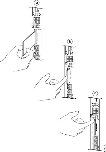
Installing a Flash Memory Card
To install a Flash memory card, complete the following steps.
Step 1
Step 2
Note
Removing a Flash Memory Card
To remove a Flash memory card from the compact Flash slot, complete the following steps. (See Figure 4-5.)
Step 1
Step 2
Step 3
Figure 4-5 Inserting and Removing a Flash Memory Card
This completes the server controller card and Flash memory installation procedures.
Replacing the Cooling Module
The Cisco AS5850 is equipped with a cooling module, designed to monitor system internal operating temperatures and maintain acceptable cooling parameters.
This section explains how to remove and replace the cooling module in the Cisco AS5850 chassis.
Tools and Parts Required
You need the following tools and parts. If you need additional equipment, contact a service representative for ordering information.
•
•
•
•
Removing the Cooling Module
Caution
Caution
To remove the cooling module, complete the following steps.
Step 1
Step 2
Step 3
Step 4
Step 5
Figure 4-6 Removing and Replacing Cooling Module
This completes the cooling module removal process. Continue with the next section, "Replacing the Cooling Module."
Replacing the Cooling Module
To replace the cooling module in the server, complete the following steps.
Caution
Step 1
Step 2
Step 3
Note
Step 4
Step 5
This completes the cooling module installation procedure. Continue with the next section, "Verifying and Troubleshooting the Installation."
Verifying and Troubleshooting the Installation
To verify that the cooling module is properly installed and operational, complete the following steps.
Step 1
Step 2
If the power LED remains off, verify that the cooling module is fully installed in the server, the connector is firmly connected to the backplane, and the captive screws are adequately tightened.
Step 3
If a fault LED lights yellow, the newly installed cooling module may be faulty or the PEMF connector may be damaged. Shut OFF the system power, remove the cooling module from the server, and check the connectors. If the connectors are in good condition, reinstall the cooling module in the server and power ON the system.
If the fault LED is still on, assume that the fan bank in the cooling module is faulty. Install another cooling module and return the faulty cooling module to the factory.
Troubleshooting the Cisco AS5850
This section describes possible causes for specific symptoms related to Cisco AS5850 hardware components and software configurations.
Note
Common Misconfigurations
The following configuration errors are common on Cisco gateways. Check each of these options against your current environment before pursuing other configuration mismatch problems.
•
•
•
•
•
•
•
System/RSC
Symptom
•
Possible Cause
•
•
•
Symptom
•
•
Possible Cause
•
•
•
Note
Cards
Symptom
•
Possible Cause
•
•
•
Note
General Configuration
Symptom
•
Possible Cause
•
•
•
Symptom
•
Possible Cause
•
•
•
Symptom
•
Possible Cause
•
•
•
•
Symptom
•
Possible Cause
•
•
Async Calls
Symptom
•
Possible Cause
•
•
•
•
•
Symptom
•
•
•
•
•
Possible Cause
•
•
•
•
Interactive Async Users
Symptom
•
Possible Cause
•
•
Interactive Users
Symptom
•
Possible Cause
•
•
Symptom
•
Possible Cause
•
•
Symptom
•
Possible Cause
•
•
Dedicated-PPP Users
Symptom
•
Possible Cause
•
•
•
•
Symptom
•
Possible Cause
•
•
•
PPP Users
Symptom
•
Possible Cause
•
•
•
•
Sync Calls
Symptom
•
Possible Cause
•
•
•
•
MMPPP
Symptom
•
Possible Cause
•
•
Symptom
•
Possible Cause
•
•
RADIUS
Symptom
•
Possible Cause
•
•
•
•
Symptom
•
Possible Cause
•
•
•
Symptom
•
Possible Cause
•
SGBP Troubleshooting
Use these debug commands:
•
•
Configuring Alarms
Environmental conditions that are monitored and may cause alarms include the following:
•
•
•
•
•
Major alarms and critical or shutdown alarms are indistinguishable on the RSC front panel. Environmental warnings and alarms are also logged to the console.
If you choose, you may configure which conditions trigger visual or audible alarms connected to the RSC front panel using the facility-alarm detect command in configuration mode.
Note
By default, the facility alarm is off. To configure alarms, use any of the following variants of the facility-alarm detect command in configuration mode (AS5850(config)# prompt).
When a configured alarm condition is detected, the facility alarm takes the following actions:
1.
2.
3.
4.
The ALARM LED and the alarm relay remain on until either all existing alarm conditions cease or the front panel Alarm Cutoff (ACO) is operated. See details later on how to instigate ACO.
After an ACO, new conditions and an increase in severity on existing conditions cause the above actions to be taken again, and so the ALARM LED is relit and the Alarm relay refires. These alarms may again be turned off using ACO. Otherwise they remain on until ALL existing alarm conditions cease to exist.