Feedback Feedback
|
Table Of Contents
Cisco AS5800 Voice over IP Feature Card Installation and Configuration
Preventing Electrostatic Discharge Damage
Cisco AS5800 Voice over IP Feature Card Installation and Configuration
Introduction
The Cisco AS5800 voice over IP feature card is a multi-DSP co-processing board and software package that adds voice over IP capabilities to the Cisco AS5800 platform. The AS5800 voice over IP feature card when used with other existing feature cards such as LAN/WAN and modem cards provides a gateway for up to 192 packetized voice/fax calls and 360 data calls per card. A Cisco AS5800 can support up to 1344 voice calls.
Note
The Cisco AS5800 must be running in split dial shelf configuration with two 7206VXR router shelves for maximum performance. Refer to Cisco AS5800 Universal Access Server Split Dial Shelf Installation and Configuration (Document number 78-6289-01) for split dial shelf configuration information.
The AS5800 voice over IP feature card resides on the dial shelf of the Cisco AS5800 platform. The on-board DSPs (Digital Signal Processors) provide the signal processing functionality to convert voice/fax information into digitized packets. The DSPs are mounted on 16 daughter cards (DSPM).
The dial shelf (DS) communicates with the voice applications on the router shelf (RS) via NIP (Nitro Interconnect Protocol) which provides both reliable and unreliable data transfer over the Backplane InterConnect Fast Ethernet.
The Cisco AS5800 voice over IP feature card can be used in many applications such as:
•
•
•
•
The Cisco AS5800 voice over IP feature card supports multiple voice codecs, fax protocols, and H.323 call signalling and gatekeeper. The Cisco AS5800 voice over IP feature card supports the following signalling protocols:
•
•
•
Note
This document includes the following sections:
•
•
•
•
•
•
Hardware Features
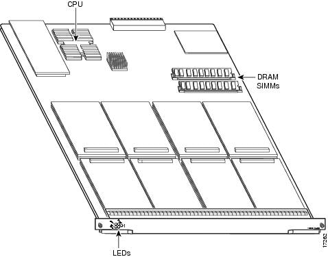
The Cisco AS5800 voice over IP feature card contains 16 (Digital Signal Processing Modules) DSPMs and a 25mhz cpu. The DSPMs are contained on16 double stacked cards on the board.
The Cisco AS5800 voice over IP card occupies a single slot in the Cisco AS5800 card chassis and connects to the LAN/WAN interface cards through the TDM backplane bus.
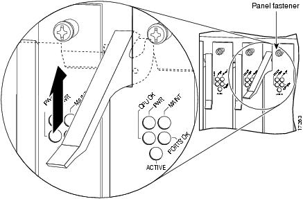
The Cisco AS5800 voice over IP feature card contains five front panel status LEDs.
A side view of the Cisco AS5800 voice over IP feature card is shown in Figure 1.
Figure 1 Voice over IP feature card
Software Features
The following software features are supported on the voice over IP feature card:
•
•
•
•
•
•
•
•
•
•
•
•
•
•
•
•
•
•
Indicators
The Cisco AS5800 voice over IP feature card contains five front panel status LEDs:
The locations of the five status LEDS is shown in Figure 2.
Figure 2
Front panel LED's
Software Requirements
The VoIP feature card and the DSP modules require Cisco IOS Release 12.0(4) XL or higher in the Cisco AS5800 universal access server.
Safety Recommendations
Follow these guidelines to ensure general safety:
•
•
•
•
•
•
Safety Warnings
Safety warnings appear throughout this publication in procedures that, if performed incorrectly, may harm you. A warning symbol precedes each safety warning.
Warning
This warning symbol means danger. You are in a situation that could cause bodily injury. Before you work on any equipment, be aware of the hazards involved with electrical circuitry and be familiar with standard practices for preventing accidents. To see translations of the warnings that appear in this publication, refer to the Regulatory Compliance and Safety Information document that accompanied this device.
Waarschuwing Dit waarschuwingssymbool betekent gevaar. U verkeert in een situatie die lichamelijk letsel kan veroorzaken. Voordat u aan enige apparatuur gaat werken, dient u zich bewust te zijn van de bij elektrische schakelingen betrokken risico's en dient u op de hoogte te zijn van standaard maatregelen om ongelukken te voorkomen. Voor vertalingen van de waarschuwingen die in deze publicatie verschijnen, kunt u het document Regulatory Compliance and Safety Information (Informatie over naleving van veiligheids- en andere voorschriften) raadplegen dat bij dit toestel is ingesloten.
Varoitus Tämä varoitusmerkki merkitsee vaaraa. Olet tilanteessa, joka voi johtaa ruumiinvammaan. Ennen kuin työskentelet minkään laitteiston parissa, ota selvää sähkökytkentöihin liittyvistä vaaroista ja tavanomaisista onnettomuuksien ehkäisykeinoista. Tässä julkaisussa esiintyvien varoitusten käännökset löydät laitteen mukana olevasta Regulatory Compliance and Safety Information -kirjasesta (määräysten noudattaminen ja tietoa turvallisuudesta).
Attention Ce symbole d'avertissement indique un danger. Vous vous trouvez dans une situation pouvant causer des blessures ou des dommages corporels. Avant de travailler sur un équipement, soyez conscient des dangers posés par les circuits électriques et familiarisez-vous avec les procédures couramment utilisées pour éviter les accidents. Pour prendre connaissance des traductions d'avertissements figurant dans cette publication, consultez le document Regulatory Compliance and Safety Information (Conformité aux règlements et consignes de sécurité) qui accompagne cet appareil.
Warnung Dieses Warnsymbol bedeutet Gefahr. Sie befinden sich in einer Situation, die zu einer Körperverletzung führen könnte. Bevor Sie mit der Arbeit an irgendeinem Gerät beginnen, seien Sie sich der mit elektrischen Stromkreisen verbundenen Gefahren und der Standardpraktiken zur Vermeidung von Unfällen bewußt. Übersetzungen der in dieser Veröffentlichung enthaltenen Warnhinweise finden Sie im Dokument Regulatory Compliance and Safety Information (Informationen zu behördlichen Vorschriften und Sicherheit), das zusammen mit diesem Gerät geliefert wurde.
Avvertenza Questo simbolo di avvertenza indica un pericolo. La situazione potrebbe causare infortuni alle persone. Prima di lavorare su qualsiasi apparecchiatura, occorre conoscere i pericoli relativi ai circuiti elettrici ed essere al corrente delle pratiche standard per la prevenzione di incidenti. La traduzione delle avvertenze riportate in questa pubblicazione si trova nel documento Regulatory Compliance and Safety Information (Conformità alle norme e informazioni sulla sicurezza) che accompagna questo dispositivo.
Advarsel Dette varselsymbolet betyr fare. Du befinner deg i en situasjon som kan føre til personskade. Før du utfører arbeid på utstyr, må du vare oppmerksom på de faremomentene som elektriske kretser innebærer, samt gjøre deg kjent med vanlig praksis når det gjelder å unngå ulykker. Hvis du vil se oversettelser av de advarslene som finnes i denne publikasjonen, kan du se i dokumentet Regulatory Compliance and Safety Information (Overholdelse av forskrifter og sikkerhetsinformasjon) som ble levert med denne enheten.
Aviso Este símbolo de aviso indica perigo. Encontra-se numa situação que lhe poderá causar danos físicos. Antes de começar a trabalhar com qualquer equipamento, familiarize-se com os perigos relacionados com circuitos eléctricos, e com quaisquer práticas comuns que possam prevenir possíveis acidentes. Para ver as traduções dos avisos que constam desta publicação, consulte o documento Regulatory Compliance and Safety Information (Informação de Segurança e Disposições Reguladoras) que acompanha este dispositivo.
¡Advertencia! Este símbolo de aviso significa peligro. Existe riesgo para su integridad física. Antes de manipular cualquier equipo, considerar los riesgos que entraña la corriente eléctrica y familiarizarse con los procedimientos estándar de prevención de accidentes. Para ver una traducción de las advertencias que aparecen en esta publicación, consultar el documento titulado Regulatory Compliance and Safety Information (Información sobre seguridad y conformidad con las disposiciones reglamentarias) que se acompaña con este dispositivo.
Varning! Denna varningssymbol signalerar fara. Du befinner dig i en situation som kan leda till personskada. Innan du utför arbete på någon utrustning måste du vara medveten om farorna med elkretsar och känna till vanligt förfarande för att förebygga skador. Se förklaringar av de varningar som förkommer i denna publikation i dokumentet Regulatory Compliance and Safety Information (Efterrättelse av föreskrifter och säkerhetsinformation), vilket medföljer denna anordning.
Safety with Electricity
Warning
Read the installation instructions before you connect the system to its power source.
Warning
Ultimate disposal of this product should be handled according to all national laws and regulations.
Warning
Before working on a chassis or working near power supplies, unplug the power cord on AC units; disconnect the power at the circuit breaker on DC units.
Warning
To ensure your safety and the safety of others, be sure the power is OFF and the power cord is unplugged before working on the router.
Warning
Before working on equipment that is connected to power lines, remove jewelry (including rings, necklaces, and watches). Metal objects will heat up when connected to power and ground and can cause serious burns or weld the metal object to the terminals.
Follow these guidelines when working on equipment powered by electricity:
•
•
•
•
•
•
•
•
•
•
•
•
Preventing Electrostatic Discharge Damage
Electrostatic discharge (ESD) can damage equipment and impair electrical circuitry. It occurs when electronic printed circuit cards are improperly handled and can result in complete or intermittent failures. Always follow ESD prevention procedures when removing and replacing cards. Ensure that the chassis is electrically connected to earth ground. Wear an ESD-preventive wrist strap, ensuring that it makes good skin contact. Connect the clip to an unpainted surface of the chassis frame to safely channel unwanted ESD voltages to ground. To properly guard against ESD damage and shocks, the wrist strap and cord must operate effectively. If no wrist strap is available, ground yourself by touching the metal part of the chassis.
CautionFor safety, periodically check the resistance value of the antistatic strap, which should be between 1 and 10 megohm (Mohm).
Required Tools
To install or remove the VoIP feature card and the DSP modules, you will need the following tools and equipment, which are not included:
•
•
•
Installing the VoIP Card
Perform the following procedure to install the voice over IP feature card.
Note
Step 1
CautionTo prevent ESD damage, handle voice over IP feature cards by ejector levers and carrier edges only, and use an ESD-preventive wrist strap or other grounding device.
Step 2
Step 3
Step 4
CautionAlways use the ejector levers to disengage or seat voice over IP feature cards in the backplane. Failure to do so can cause erroneous system error messages indicating a card failure; however, do not use the ejector levers to lift or support the weight of the cards.
Step 5
CautionAlways tighten the panel fasteners on voice over IP feature cards. These fasteners prevent accidental removal and provide proper grounding for the system.
Step 6
Removing the VoIP Card
To remove the VoIP card, follow the steps below:
Step 1
CautionTo prevent ESD damage, handle voice over IP feature cards by ejector levers and carrier edges only, and use an ESD-preventive wrist strap or other grounding device.
Step 2
Step 3
CautionAlways use the ejector levers to disengage or seat voice over IP feature cards in the backplane. Failure to do so can cause erroneous system error messages indicating a card failure; however, do not use the ejector levers to lift or support the weight of the cards.
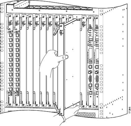
CautionHigh performance devices on the VoIP card can get hot during operation. Exercise caution when you remove the VoIP card during operation.
Step 4
Figure 3 Removing a voice over IP feature card
Step 5
Step 6
Cisco Connection Online
Cisco Connection Online (CCO) is Cisco Systems' primary, real-time support channel. Maintenance customers and partners can self-register on CCO to obtain additional information and services.
Available 24 hours a day, 7 days a week, CCO provides a wealth of standard and value-added services to Cisco's customers and business partners. CCO services include product information, product documentation, software updates, release notes, technical tips, the Bug Navigator, configuration notes, brochures, descriptions of service offerings, and download access to public and authorized files.
CCO serves a wide variety of users through two interfaces that are updated and enhanced simultaneously: a character-based version and a multimedia version that resides on the World Wide Web (WWW). The character-based CCO supports Zmodem, Kermit, Xmodem, FTP, and Internet e-mail, and it is excellent for quick access to information over lower bandwidths. The WWW version of CCO provides richly formatted documents with photographs, figures, graphics, and video, as well as hyperlinks to related information.
You can access CCO in the following ways:
•
•
•
•
•
For a copy of CCO's Frequently Asked Questions (FAQ), contact cco-help@cisco.com. For additional information, contact cco-team@cisco.com.
Note
New Hardware Features
A description of new hardware features available after the release of this document can be found at the following URL:
http://www.cisco.com/univercd/cc/td/doc/product/access/acs_serv/5800/5800cfg/index.htm
If You Need More Information
Cisco documentation and additional literature are available in a CD-ROM package, which ships with your product. The Documentation CD-ROM, a member of the Cisco Connection Family, is updated monthly. Therefore, it might be more current than printed documentation. To order additional copies of the Documentation CD-ROM, contact your local sales representative or call customer service. The CD-ROM package is available as a single package or as an annual subscription. You can also access Cisco documentation on the World Wide Web at http://www.cisco.com, http://www-china.cisco.com, or http://www-europe.cisco.com.
If you are reading Cisco product documentation on the World Wide Web, you can submit comments electronically. Click Feedback in the toolbar and select Documentation. After you complete the form, click Submit to send it to Cisco. We appreciate your comments.
If you want to order printed documentation, see the Cisco Connection Online
section.
78-6070-01