Feedback Feedback
|
Table Of Contents
AC-Input Power Shelf and Power Supply Installation and Replacement
Cisco AS5800 Universal Access Server Overview
Rack-Mounting the AC-Input Power Shelf
Removing and Replacing a Power Supply
Installing the Power Shelf in the Rack
Connecting the Power Cables and Powering Up the System
Connecting the DC Power Cables
Grounding the AC-Input Power Shelf to the Dial Shelf
Verifying and Troubleshooting the Installation
AC-Input Power Shelf and Power Supply Installation and Replacement
Product Numbers: AS58-360-AC, AS58-720-AC, DS58-PWR-2AC(=), DS58-PWR-AC=, DS58-CAB-MBUS=, DS58-CAB-ACDC=
The AC-input power shelf is an optional component of the Cisco AS5800 Universal Access Server and is used to convert AC-input power into DC-output power for the DC-powered Cisco 5814 dial shelf. The AC-input power shelf contains two AC-input power supplies.
This document explains how to rack-mount the AC-input power shelf, attach the power cables, and verify the initialization after you power up the system. This document also explains how to remove and replace an individual power supply in the power shelf.
Note
Use this document in conjunction with the Cisco AS5800 Universal Access Server Hardware Installation and Configuration Guide and the Cisco AS5800 Universal Access Server Software Installation and Configuration Guide that shipped with your system.
Document Contents
The following sections are included in this document:
•
•
•
•
If You Need More Information
For information regarding the Cisco AS5800 Universal Access Server that is beyond the scope of this document or for additional information, use the following resources:
•
•
•
•
•
Cisco documentation and additional literature are available in a CD-ROM package, which ships with your product. The Documentation CD-ROM, a member of the Cisco Connection Family, is updated monthly; therefore, it might be more current than printed documentation. To order additional copies of the Documentation CD-ROM, contact your local sales representative or call customer service. The CD-ROM package is available as a single package or as an annual subscription. You can also access Cisco documentation on the World Wide Web at http://www.cisco.com, http://www-china.cisco.com, or http://www-europe.cisco.com.
If you are reading Cisco product documentation on the World Wide Web, you can submit comments electronically. Click Feedback on the toolbar, and then select Documentation. After you complete the form, click Submit to send it to Cisco. We appreciate your comments.
•
•
•
•
•
•
•
•
•
•
•
•
•
•
Cisco AS5800 Universal Access Server Overview
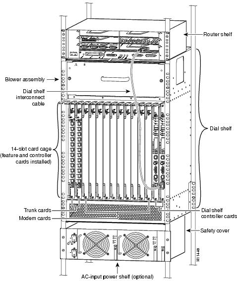
The Cisco AS5800 Universal Access Server is a high-density, ISDN and modem WAN aggregation system that provides both digital and analog call termination. It is intended to be used in service provider dial point-of-presence (POP), or centralized enterprise dial environments. The Cisco AS5800 Universal Access Server chassis components include a Cisco 5814 dial shelf and a Cisco 7206 router shelf. An optional AC power shelf is also available.
The dial shelf and router shelf are bundled, and can be ordered to support either AC or DC power. Included in the dial shelf is a blower assembly, filter module, and power entry modules (PEMs). Also included in the bundled system are ingress trunk cards, modem cards, dial shelf controller cards, Flash memory PCMCIA cards, cables, and Cisco IOS software. The dial shelf feature cards and host router shelf communicate via a dial shelf interconnect cable.
The Cisco AS5800 Universal Access Server can be configured for dual load-sharing, AC- or DC-input power. AC-input power is accepted via a separate, self-contained AC-input power shelf, which converts AC-input power into DC-output for use by the DC-powered dial shelf. The AC-input power shelf is rack mounted and has a safety cover that shields the electrical connections in the power shelf rear.
The AC-input to DC-output connection supplies -48V DC-output power to two DC power supplies, called power entry modules (PEMs), in the dial shelf. The PEMs receive the -48 volts and transmit power to the filter module. Power flows through the filter module to the backplane where it is distributed to the dial shelf controller card(s) and feature cards.
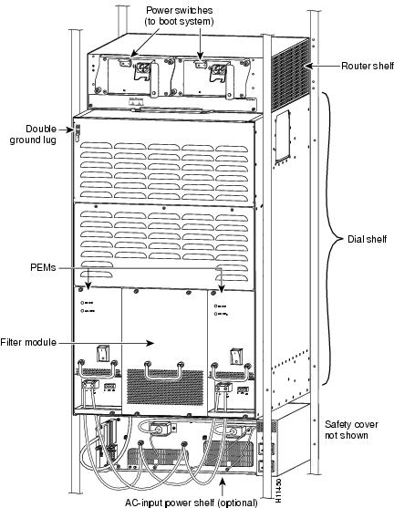
shows a front view of a fully configured Cisco AS5800 Universal Access Server, and shows a rear view.
Figure 1 Cisco AS5800 Universal Access Server with AC-Input Power Shelf—Front View
Figure 2 Cisco AS5800 Universal Access Server with AC-Input Power Shelf—Rear View
AC-Input Power Shelf Overview
The AC-input power shelf includes two 2,000-watt (W) AC-input power supplies that plug into a common power backplane in the AC-input power shelf. A single AC-input power supply is capable of powering a fully configured Cisco 5814 dial shelf. A second power supply provides full redundancy.
During normal operation, the dual AC-input power supplies provide automatic load-sharing, with each power supply supporting 50 percent of the power load. When you remove one of the AC-input power supplies, the remaining power supply immediately ramps up to full power and maintains uninterrupted system power.
Note
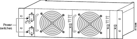
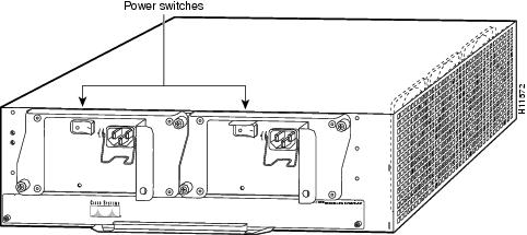
Each AC-input power supply is powered ON by a separate power switch, which is located on the AC-input power shelf front panel (). Ejector levers with locking spring clips secure each power supply to the backplane connectors, and a handle on each power supply allows you to remove and replace the power supplies with ease.
Figure 3 Cisco 5800 AC-Input Power Shelf—Front View
The AC-input power shelf is three rack units high [5.25 inches (13.32 cm)], and mounts underneath the dial shelf in a standard 19-inch, 4-post or telco-type rack assembly. Note the rack placement of the AC-input power shelf in Figure 1.
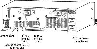
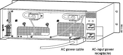
All cable connections for AC-input power, DC-output power, and status signals are made from the AC-input power shelf rear. (See ) Two modular power cables connect each AC-input power supply to the site AC-input power source. Two DC-interconnect cables provide DC-output power to the dial shelf. A monitor cable provides a status signal connection to the dial shelf filter module maintenance bus (MBus), which monitors voltage tolerance levels, temperature conditions, and power failure in the AC-input power shelf. A grounding cable provides a ground connections from the AC-input power shelf to the dial shelf.
Figure 4 Cisco 5800 AC-Input Power Shelf—Rear View
Specifications
The AC-input power supply operates between 200 and 240 VAC input voltage and supplies -48 VDC to the dial shelf. The AC-input power supply uses a power factor corrector (PFC) that automatically adjusts for the input voltage being supplied.
lists the AC-input power supply specifications.
Table 1 AC-Input Power Supply Specifications
Input power requirement
2666.66 volt amps (VA)
Input voltage
200 to 240 VAC1
Input frequency
50 to 60 hertz (Hz)
Power factor
0.90 at 50% of full load; 0.99 at full load
Power output
2000W with a maximum configuration and one or two AC-input power supplies
Voltage out (VO) set point:
-48.0 VDC2 typical. Frame GND strappable to either output terminal.
Current out (IO) rated:
0 to 41.6 amps DC; 2000W maximum
Output current limit
(steady state)
58.1 amps DC maximum
Efficiency
88% at full load, 240 VAC, with ORing diode
DC-output stud torque
25 in. lb
Dimensions (H x W x D)
5.25 x 17 x 14.4 in. (13.32 x 43.2 x 35.88 cm)
Weight
Per power supply: 14.5 lb (6.6 kg)
Empty power shelf: 18 lb (8.16 kg)
Heat dissipation
1037 Btu/hr
AC power cable supplied
12 American Wire Gauge (AWG), 16-amp3
DC interconnect cable supplied
6 AWG, 2 pairs (black and red)
Storage temperature
25.8 to 185 °F (-40 to 85 °C)
Operating Temperature
(air inlet to power unit)32 to 122 °F (0 to 50 °C) airflow front to back with 3 clearance for exhaust air in unpressurized enclosure
Acoustics
60 dBA typical; sound pressure level measured at 1 m
Humidity (noncondensing)
5 to 95%
Altitude
-200 to 13,000 ft (-61 to 3,962 meters); derate at -7 °C/1000 ft. above 8000 ft
Shock and Vibration
Lucent L-533809
ESD
IEC1000-4-2
Reliability (at 40 °C, 200 VAC, 1600 W)
7500 FITS per TR-EOP-000332
1.5 x 10⁵ hours MTBF per RIN
Agency approvals
CE
UL
CSA
VDEFor compliance information refer to the Cisco AS5800 Universal Access Server Regulatory Compliance and Safety Information document that shipped with your system.
1 VAC = volts alternating current.
2 VDC = volts direct current
3 Each AC-input power supply requires a minimum of 15-amp service, with a 15-amp receptacle at the power source. The power cable supplied with the AS5800 AC-input power shelf uses a 16-amp male plug
AC-Input Power Shelf Cables
The AC-input power shelf is equipped with four types of cables:
•
•
•
•
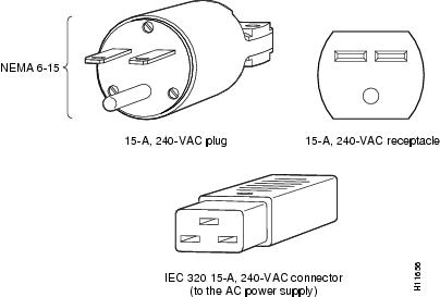
The AC-input connection uses a 16A/250 VAC power cord in Europe and Asia, and a 20A/240 VAC power cord in North America. The 20-amp connectors on the AC-input power shelf are incompatible with 15-amp power strips used in most equipment racks and with the power source used for the router shelf.
Note
Figure shows a 20-amp power plug and receptacle used in North America.
Figure 5 20-Amp AC Power Cord Connector and Plug, and 20-Amp Receptacle
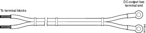
The DC interconnect cables supplied with your AC-input power shelf (see Figure 6) attach to bus terminal studs in the AC-input power shelf via ring-lug connectors; the cables then connect to the DC terminal blocks in each PEM.
Figure 6 DC Interconnect Cables
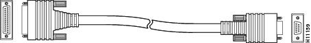
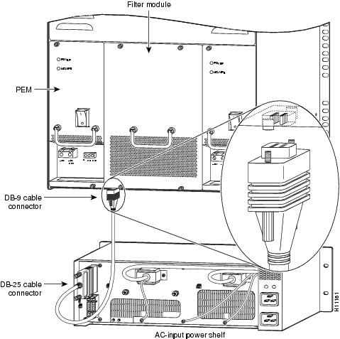
The monitor cable has a DB-25 connector on the AC-input power shelf end and a DB-9 connector on the dial shelf end that connects to the dial shelf filter module. Figure 7 shows the monitor cable connectors and receptacles.
Figure 7 Monitor Cable
describes the DB-9 connector pin functions.
Table 2 Monitor Cable DB-9 Connector Pinout—Filter Module
Table describes the DB-25 connector pin functions.
Table 3
Monitor Cable DB-25 Connector Pinout—AC Power Shelf
Power Shelf LED Indicators
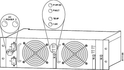
The AC-input power shelf includes two LEDs that are located on the left front of the power shelf and four LEDs that are located on the front of each power supply. (See Figure 8.)
Figure 8 Power Supply LEDs
The AC-input power supply LEDs are summarized in .
Table 4
AC-Input Power Supply LEDs
Power Supply Safety Features
The power supplies have the following safety features:
•
•
•
•
•
Internal monitoring data is passed to the dial shelf via the maintenance bus (MBus) monitoring system. You can view this data through a terminal connected to the router shelf console port. The command to display the monitoring information is described in the Cisco AS5800 Universal Access Server Software Installation and Configuration Guide (DOC-AS5800-SICG=).
Safety Guidelines
The AC-input power supplies are hot-swappable, which allows you to remove or replace a power supply without affecting system operation. Before removing a redundant power supply, ensure the remaining power supply is powered ON for uninterrupted system operation.
This section provides safety guidelines to help you avoid injury to yourself and avoid damage to the equipment. The following safety guidelines are recommended when working with any equipment that connects to electrical power or telephone wiring:
•
•
•
•
•
•
•

Safety Warnings
Safety warnings appear throughout this publication in procedures that, if performed incorrectly, may harm you. A warning symbol precedes each warning statement. To see translations of safety warnings pertaining to the access server, refer to the Cisco AS5800 Universal Access Server Regulatory Compliance and Safety Information document that shipped with your Cisco AS5800 Universal Access Server.
Waarschuwing Dit waarschuwingssymbool betekent gevaar. U verkeert in een situatie die lichamelijk letsel kan veroorzaken. Voordat u aan enige apparatuur gaat werken, dient u zich bewust te zijn van de bij elektrische schakelingen betrokken risico's en dient u op de hoogte te zijn van standaard maatregelen om ongelukken te voorkomen. Voor vertalingen van de waarschuwingen die in deze publicatie verschijnen, kunt u het document Regulatory Compliance and Safety Information (Informatie over naleving van veiligheids- en andere voorschriften) raadplegen dat bij dit toestel is ingesloten.
Varoitus Tämä varoitusmerkki merkitsee vaaraa. Olet tilanteessa, joka voi johtaa ruumiinvammaan. Ennen kuin työskentelet minkään laitteiston parissa, ota selvää sähkökytkentöihin liittyvistä vaaroista ja tavanomaisista onnettomuuksien ehkäisykeinoista. Tässä julkaisussa esiintyvien varoitusten käännökset löydät laitteen mukana olevasta Regulatory Compliance and Safety Information -kirjasesta (määräysten noudattaminen ja tietoa turvallisuudesta).
Attention Ce symbole d'avertissement indique un danger. Vous vous trouvez dans une situation pouvant causer des blessures ou des dommages corporels. Avant de travailler sur un équipement, soyez conscient des dangers posés par les circuits électriques et familiarisez-vous avec les procédures couramment utilisées pour éviter les accidents. Pour prendre connaissance des traductions d'avertissements figurant dans cette publication, consultez le document Regulatory Compliance and Safety Information (Conformité aux règlements et consignes de sécurité) qui accompagne cet appareil.
Warnung Dieses Warnsymbol bedeutet Gefahr. Sie befinden sich in einer Situation, die zu einer Körperverletzung führen könnte. Bevor Sie mit der Arbeit an irgendeinem Gerät beginnen, seien Sie sich der mit elektrischen Stromkreisen verbundenen Gefahren und der Standardpraktiken zur Vermeidung von Unfällen bewußt. Übersetzungen der in dieser Veröffentlichung enthaltenen Warnhinweise finden Sie im Dokument Regulatory Compliance and Safety Information (Informationen zu behördlichen Vorschriften und Sicherheit), das zusammen mit diesem Gerät geliefert wurde.
Avvertenza Questo simbolo di avvertenza indica un pericolo. La situazione potrebbe causare infortuni alle persone. Prima di lavorare su qualsiasi apparecchiatura, occorre conoscere i pericoli relativi ai circuiti elettrici ed essere al corrente delle pratiche standard per la prevenzione di incidenti. La traduzione delle avvertenze riportate in questa pubblicazione si trova nel documento Regulatory Compliance and Safety Information (Conformità alle norme e informazioni sulla sicurezza) che accompagna questo dispositivo.
Advarsel Dette varselsymbolet betyr fare. Du befinner deg i en situasjon som kan føre til personskade. Før du utfører arbeid på utstyr, må du vare oppmerksom på de faremomentene som elektriske kretser innebærer, samt gjøre deg kjent med vanlig praksis når det gjelder å unngå ulykker. Hvis du vil se oversettelser av de advarslene som finnes i denne publikasjonen, kan du se i dokumentet Regulatory Compliance and Safety Information (Overholdelse av forskrifter og sikkerhetsinformasjon) som ble levert med denne enheten.
Aviso Este símbolo de aviso indica perigo. Encontra-se numa situação que lhe poderá causar danos físicos. Antes de começar a trabalhar com qualquer equipamento, familiarize-se com os perigos relacionados com circuitos eléctricos, e com quaisquer práticas comuns que possam prevenir possíveis acidentes. Para ver as traduções dos avisos que constam desta publicação, consulte o documento Regulatory Compliance and Safety Information (Informação de Segurança e Disposições Reguladoras) que acompanha este dispositivo.
¡Advertencia! Este símbolo de aviso significa peligro. Existe riesgo para su integridad física. Antes de manipular cualquier equipo, considerar los riesgos que entraña la corriente eléctrica y familiarizarse con los procedimientos estándar de prevención de accidentes. Para ver una traducción de las advertencias que aparecen en esta publicación, consultar el documento titulado Regulatory Compliance and Safety Information (Información sobre seguridad y conformidad con las disposiciones reglamentarias) que se acompaña con este dispositivo.
Varning! Denna varningssymbol signalerar fara. Du befinner dig i en situation som kan leda till personskada. Innan du utför arbete på någon utrustning måste du vara medveten om farorna med elkretsar och känna till vanligt förfarande för att förebygga skador. Se förklaringar av de varningar som förkommer i denna publikation i dokumentet Regulatory Compliance and Safety Information (Efterrättelse av föreskrifter och säkerhetsinformation), vilket medföljer denna anordning.
Rack-Mounting Considerations
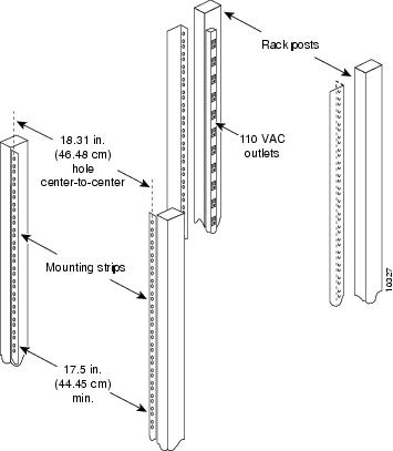
The rack-mounting hardware provided with your AC-input power shelf is suitable for standard 19-inch, 4-post and telco-type equipment racks. Use the permanent mounting flanges on the front of the power shelf to install the power shelf in the rack.
Note
Some equipment racks provide a power strip along the length of one of the rack mounting strips. If your rack has a power strip, consider the position of the strip when planning fastener points to ensure you will be able to slide power supplies into and out of their respective bays. If the power strip impairs a rack-mount installation, remove the power strip before installing the power shelf in the rack, then replace it after the power shelf is installed.
Figure 9 shows a typical 19-inch, 4-post equipment rack with a power strip along one of the back posts.
Note
Figure 9 Typical 19-Inch Equipment Rack Posts and Mounting Strips
When using the rack-mounting hardware provided with your power shelf, consider the following guidelines:
•
•
•
When planning your rack installation, consider the following guidelines:
•

Caution
•
•
•
•
•
•
•
•

•


Rack-Mounting the AC-Input Power Shelf
This section lists tools and parts you need to remove and replace individual power supplies, and explains how to install the AC-input power shelf in an equipment rack.
Tools and Parts Required
You need the following tools and parts to rack mount the power shelf:
•
•
•
•
•
•
•
•
•
•
•
•
•
You need the following tools and parts to remove and replace an individual power supply:
•
•
•
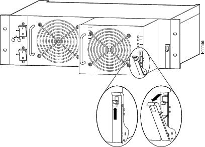
Removing and Replacing a Power Supply
Use the following procedure if you are replacing a faulty power supply or if you want to reduce the weight of the power shelf before you install it in a rack. If you do not want to remove power supplies prior to rack-mounting the AC-input power shelf, skip this section and proceed to the section "Installing the Power Shelf in the Rack."
The AC-input power shelf is configured with two power supplies. You can remove or replace one of the power supplies without affecting system operation. When power is removed from one supply, the redundant power feature causes the second power supply to ramp up to full power and maintain uninterrupted system operation.
To remove a power supply, follow these steps:

Caution
Step 1
Step 2
Note
Step 3
Step 4
Figure 10 Removing and Replacing a Power Supply
Step 5
To replace the power supply, follow these steps:
Step 1
Step 2
This completes the power supply replacement procedure. Proceed to the section "Installing the Power Shelf in the Rack" to rack-mount the power shelf.
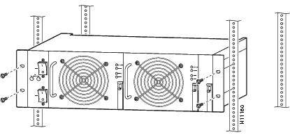
Installing the Power Shelf in the Rack
You install the power shelf in the rack by securing the permanent mounting flanges to two posts or mounting strips in the rack using the slotted mounting screws provided. Because the mounting flanges support the weight of the entire power shelf, be sure to use at least two slotted screws per mounting flange.
Note

Caution
To install the power shelf in the rack, follow these steps:
Step 1
Step 2
Step 3
Step 4
Step 5
Figure 11 illustrates the AC-input power shelf installed in a 4-post rack.
Figure 11 Installing the AC-Input Power Shelf in a 4-Post Rack
To connect the power cables and power up the system, proceed to the section "Connecting the Power Cables and Powering Up the System."
Connecting the Power Cables and Powering Up the System
You need to connect all cables between the AC-input power shelf and the dial shelf before you connect the power shelf to your AC power source. You also need to install the provided electrical connection safety cover at the rear of the power shelf before you power up the system.

You need the following parts and tools to connect the power cables:
•
•
•
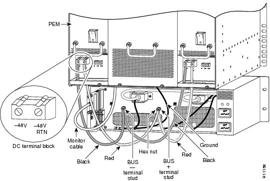
Connecting the DC Power Cables
To connect the DC interconnect power cables, complete the following steps:
Step 1
Step 2
Step 3
Step 4
Step 5
Figure 12 Connecting the DC-Interconnect Cables
Step 6
Step 7
Step 8
Note
This completes the DC power cabling installation. You must now connect the monitor cable from the AC-input power shelf to the dial shelf filter module.
Connecting the Monitor Cable
To connect the monitor cable, complete the following steps:
Step 1
Step 2
Step 3
Step 4
Figure 13 Connecting the Monitor Cable
This completes the monitor cable installation. You must now ground the AC-input power shelf to the dial shelf.
Grounding the AC-Input Power Shelf to the Dial Shelf
To attach the ground cable between the AC-input power shelf and the dial shelf, complete the following steps:
Step 1
Step 2
Step 3
Step 4
Step 5
Figure 14 Attaching the Ground Wire
This completes the ground cable installation. You must now connect the AC-input power cords.
Connecting the AC Power Cords
To connect the AC power cords, complete the following steps:
Step 1
Step 2
Note
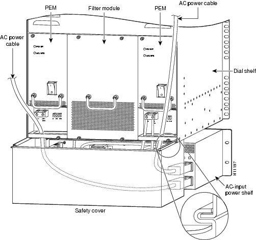
Figure 15 Connecting the AC Power Cords
This completes the AC power cord installation.
Installing the Safety Cover
For safety reasons, you must install the metal safety cover that shipped with your AC-input power shelf before you power up the system. The safety cover shields the power connections from possible short circuit and protects you from electrical shock.
To install the safety cover, follow these steps:
Step 1
Step 2
Figure 16 Installing the Safety Cover
This completes the AC-input power shelf installation.
Powering On the Access Server
After installing your AC-input power shelf and connecting the cables, you start up the system by powering on the following components:
•
•
•
To power on the system, complete the following steps:
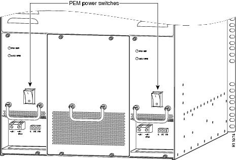
Step 1
Step 2
Figure 17 Power Entry Module (PEM) Power Switches
Step 3
Note
Figure 18 AC-Input Power Shelf—Front View
Step 4
Figure 19 Router Shelf Power Switches—Rear View
Step 5
This completes the process for installing and cabling the AC-input power shelf and for powering on the access server. For installation troubleshooting tips, proceed to the section "Verifying and Troubleshooting the Installation."
Verifying and Troubleshooting the Installation
To complete the installation, verify that the power supply LEDs operate properly as follows. (Review the descriptions of the LEDs in the section "Power Shelf LED Indicators" earlier in this document.)
•
If a power supply power LED is off, verify the associated AC power cord is plugged in, and the correct AC voltage (200 to 240 VAC) is present at the source.
•
If a power supply fault LED lights, the power shelf has detected an internal fault; the power supply is defective. You must replace the power supply.
•
If a power supply overtemperature LED lights, verify that the ambient temperature is below 50 C and the air intake is not blocked. If the condition persists, replace the power supply.
•
If a power supply current limit LED lights, verify that the DC-output terminals on the AC-input power shelf rear are not short circuited, and an approved dial shelf configuration is being used.
Note
If a power supply fails to operate properly after several attempts to initialize it, contact a service representative for assistance.
This completes the power supply installation. Refer to the Cisco AS5800 Universal Access Server Hardware Installation and Configuration Guide for system installation troubleshooting procedures, and to the Cisco AS5800 Universal Access Server Software Installation and Configuration Guide for descriptions and examples of software features and commands.
Cisco Connection Online
Cisco Connection Online (CCO) is Cisco Systems' primary, real-time support channel. Maintenance customers and partners can self-register on CCO to obtain additional content and services.
Available 24 hours a day, 7 days a week, CCO provides a wealth of standard and value-added services to Cisco's customers and business partners. CCO services include product information, software updates, release notes, technical tips, the Bug Navigator, configuration notes, brochures, descriptions of service offerings, and download access to public and authorized files.
CCO serves a wide variety of users through two interfaces that are updated and enhanced simultaneously—a character-based version and a multimedia version that resides on the World Wide Web (WWW). The character-based CCO supports Zmodem, Kermit, Xmodem, FTP, and Internet e-mail, and is excellent for quick access to information over lower bandwidths. The WWW version of CCO provides richly formatted documents with photographs, figures, graphics, and video, as well as hyperlinks to related information.
You can access CCO in the following ways:
•
•
•
•
•
For a copy of CCO's Frequently Asked Questions (FAQ), contact cco-help@cisco.com. For additional information, contact cco-team@cisco.com.
Note
78-4659-01