Feedback
Table Of Contents
Problem Solving with Subsystems
Problem Solving with Subsystems—Cisco 7206 Router
Starting Up the Cisco 7206 Router Shelf
Troubleshooting the Router Installation
Starting Up the Cisco 5814 Dial Shelf
Troubleshooting the Power Subsystems
Troubleshooting the Cooling Subsystems
Router Shelf Cooling Subsystem
Troubleshooting the Processor Subsystems
Troubleshooting the Router Shelf Processor Subsystem
Troubleshooting the I/O Controller Card
Troubleshooting the Network Processor Card
Troubleshooting the Port Adapters
Troubleshooting the Dial Shelf Interconnect Port Adapter
Troubleshooting the Dial Shelf Processor Subsystem
Troubleshooting the Dial Shelf Controller Card
Troubleshooting the Dial Shelf Cards
Troubleshooting Network Interfaces
Hardware Troubleshooting
Your Cisco AS5800 was thoroughly tested before leaving the factory. If you encounter problems initializing system startup, use the information in this chapter to help isolate the cause.
This chapter contains the following sections:
•
Problem Solving with Subsystems
•
•
•
•
The procedures in this chapter assume that you are troubleshooting the initial hardware configuration and system startup. If you have removed or replaced components or changed any default settings, the recommendations in this chapter might not apply. Review the safety warnings listed in the publication Cisco AS5800 Universal Access Server Regulatory Compliance and Safety Information before using the troubleshooting procedures in this chapter.
If you are unable to resolve the problem, contact a customer service representative for assistance and further instructions. Provide the representative with the following information:
•
•
•
•
•
•
Problem Solving with Subsystems
The key to problem solving is isolating the problem to a specific subsystem. The first step in solving startup problems is to compare what the system is doing to what it should be doing. Try to isolate the problem to one of the following three router shelf or dial shelf subsystems:
•
•
•
Start by checking the router shelf power components. If the problem does not seem to originate there, check the dial shelf power components.
Router shelf power components include the following:
•
•
•
Dial shelf power components include the following:
•
•
•
•
•
•
Next, check the router shelf cooling components. If the problem does not seem to originate there, check the dial shelf cooling components. Router shelf and dial shelf fans should all be operating whenever system power is on.
•
•
Last, check the router shelf processor cards. If the problem does not seem to originate there, check the dial shelf processor cards.
Most processor cards contain LEDs that indicate the status of the card. Observing these LEDs can help you isolate the problem to a particular card. (See Chapter 4, "Powering On the Cisco AS5800 and Observing Initial Startup Conditions," for LED descriptions and troubleshooting tips.)
The system memory and management functions reside on the router shelf I/O controller card and the network processor card. The enabled LED on each port adapter lights when the port adapter is initialized. A port adapter that is partially plugged into the midplane can cause the system to hang and crash.
The router shelf processor subsystem includes the following:
•
•
•
•
Dial shelf processor cards include the following:
•
•
•
The following sections will help you isolate a problem within one of these subsystems and direct you to the appropriate troubleshooting section.
Problem Solving with Subsystems—Cisco 7206 Router
The key to solving problems with the system is isolating the problem to a specific subsystem. The first step in solving startup problems is to compare what the system is doing to what it should be doing. Because a startup problem is usually caused by a single component, it is more efficient to isolate the problem to a subsystem rather than to troubleshoot each component in the system. For these troubleshooting procedures, consider the following subsystems:
•
•
•
You can quickly verify that your new router shelf is properly installed and operative by observing the router LEDs as described in the "Starting the Cisco 7206" section on page 4-8.
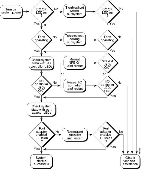
Figure 5-1 Troubleshooting Strategy for Startup Problems
Identifying Startup Problems
Hardware startup problems are commonly traced to cabling problems or incorrectly installed power supplies or cards. In rare cases, problems are caused by part failures.
When you start up a Cisco AS5800 for the first time, you should observe the startup sequence, described in the following sections. This chapter describes the normal startup sequence for the router shelf and the dial shelf and the steps to take if the system does not perform that sequence as expected.
In most cases, LEDs indicate system states in the startup sequence. By checking these LEDs, you can determine when and where the system failed. Use the following descriptions to isolate the problem to a subsystem, then proceed to the appropriate sections to try to resolve the problem.
Note
Starting Up the Cisco 7206 Router Shelf
When you first power ON the router shelf power supply, the following should occur:
•
If the power OK LEDs do not light, proceed to the section "Troubleshooting the Power Subsystems."
•
If the fans do not operate, proceed to the section "Troubleshooting the Cooling Subsystems."
•
•
•
•
•
•
During a successful router boot, these LEDs light and remain on if a Flash memory card is present in the slot. These LEDs also blink when either slot is being accessed by the system. These LEDs do not indicate startup problems.
•
The enabled LED indicates that the port adapter is receiving power and has been recognized by the network processor card; it does not indicate the state of the individual port adapter interfaces.
If an enabled LED does not light, proceed to the section "Troubleshooting the Port Adapters," later in this chapter.
•
The link status LED indicates an active connection to the dial shelf and lights when the interconnect port adapter is receiving a carrier signal from the dial shelf controller card. This LED should light and remain on when the access server is operating.
If the interconnect port adapter link LED does not light, proceed to the section, "Troubleshooting the Dial Shelf Interconnect Port Adapter."
•
Troubleshooting the Router Installation
Your Cisco 7206 routers went through extensive testing before leaving the factory. However, if you encounter problems starting the routers, use the information in the chapter "Troubleshooting the Installation" in the Cisco 7206 Installation and Configuration Guide (Document Number DOC-7206-ICG=) to help isolate the cause of the problems. Be sure to review the safety warnings listed in the publication Regulatory Compliance and Safety Information for the Cisco 7200 Series Routers (Part Number 78-3419-xx) that accompanied your Cisco 7206 before using troubleshooting procedures.
If you are unable to easily solve the problem, contact a customer service representative for assistance and further instructions. Be prepared to provide the representative with the following information:
•
•
•
•
•
•
shows the general troubleshooting strategy for Cisco 7206 routers. Refer to this chart, as necessary, to isolate problems to a specific subsystem; then resolve the problem if possible.
Starting Up the Cisco 5814 Dial Shelf
When you first power ON the dial shelf, the following should occur:
•
If the green power LEDs do not light, proceed to the section "Troubleshooting the Power Subsystem."
•
If the fans do not operate, proceed to the section "Troubleshooting the Cooling Subsystems."
•
•
If the MBus LED remains off but the power LED is on, there might be a problem with the MBus power supply on the card. Replace the card.
•
•
If the dial shelf processor component LEDs do not light as described, proceed to the section "Troubleshooting the Processor Subsystems."
Troubleshooting the Power Subsystems
The Cisco AS5800 is designed to minimize problems in the power subsystem. The power subsystem includes the router shelf power supplies, the dial shelf PEMs and filter module, and the AC-input power shelf (if used).
The access server comes with two DC power supplies in both the router shelf and the dial shelf, which allow you to replace power supplies while the system is operating. However, if you are using an AC-configured system and you discover a faulty PEM, you must power off the system before performing a replacement.
Caution
The failure of a single power supply in the router shelf, the dial shelf, or the AC-input power shelf, if used, will not stop the access server from operating; however, to maintain power redundancy, both power supplies in each unit must be receiving power.
Router Shelf Power Subsystem
In the router shelf, check the following to help isolate a problem with the power subsystem:
•
•
•
If the power OK LED remains off and the power switch is set correctly, suspect the power source or the power cable. Power OFF the system, connect the power cable to another power source, if available, then power ON the system. If the LED lights, the problem is the first power source.
•
•
•
•
•
If you are unable to resolve the problem or you determine that either a power supply or chassis connector is faulty, contact a service representative for instructions.
Dial Shelf Power Subsystem
In the dial shelf, check the following to help isolate a problem with the power subsystem:
•
•
•
If the DC-input connection is wired correctly, the miswire LED remains off.
If the miswire LED is on, the two DC conductors entering the PEM terminal block are reversed. Power OFF the power at your power source and reverse the connections.
•
•
•
•
•
If a power supply fault LED lights, the power shelf has detected an internal fault; the power supply is defective. You need to replace the power supply.
•
If a power supply overtemperature LED lights, verify that the ambient temperature is below 120°F (50°C) and the air intake is not blocked. If the condition persists, replace the power supply.
•
If a power supply current limit LED lights, verify that the DC bus terminals on the AC-input power shelf rear are not short-circuited and a supported dial shelf configuration is being used.
Note
Troubleshooting the Cooling Subsystems
The Cisco AS5800 is designed to minimize problems in the cooling subsystem. The access server can operate in temperatures of up to 120°F (50°C) for a maximum of 72 hours. The access server also contains rendundant fans in both the router shelf fan tray and the dial shelf blower assembly, which allow the system to continue operating despite a single fan failure. Both the router shelf fan tray and the dial shelf blower assembly can be removed and replaced while the system is operating, provided the procedure does not exceed 1 min.
Router Shelf Cooling Subsystem
In the router shelf, check the following to help isolate a problem with the cooling subsystem:
•
To determine whether the router shelf fans are operating, listen for them. In noisy environments, place your hand on the left side of the router shelf (when viewing the router shelf from the front) to feel for air being forced out the vents.
•
•
If you determine that the power supply is functioning normally but a fan is faulty, you can replace the fan tray without powering off the access server. Contact a customer service representative if you need assistance.
For problems with the system power, refer to the section "Troubleshooting the Power Subsystem" in this chapter.
Dial Shelf Cooling Subsystem
In the dial shelf, check the following to help isolate a problem with the cooling system:
•
To determine whether the dial shelf fans are operating, listen for them. In noisy environments, place your hand under the exhaust vents on the back of the dial shelf blower assembly to feel for air being forced out the vents.
•
If you determine that the power supply is functioning normally but a fan is faulty, you can replace the blower assembly without powering off the access server. Refer to the blower assembly removal instructions in ","and the reinsertion instructions in "." For problems with the system power, refer to the section "Troubleshooting the Power Subsystem" in this chapter.
•
If no, verify that the blower assembly is fully installed in the dial shelf, the connector is firmly connected to the backplane, and the captive screws are tightened adequately.
•
If yes, the newly installed blower assembly might be faulty or the chassis connector might be damaged. Shut off system power, remove the blower assembly from the dial shelf, and check the connectors. If the connectors are in good condition, reinstall the blower assembly in the dial shelf and power ON the system. If the fault LED is still on, assume that the blower assembly is faulty. Install another blower assembly and return the faulty blower assembly to the factory.
•
Queued messages:%ENVM-1-SHUTDOWN: Environmental Monitor initiated shutdownIf an environmental shutdown results from an out-of-tolerance power condition, the router shelf power OK LED remains off and the system shuts down. (Refer to the section "Troubleshooting the Power Subsystems" in this chapter.) Although an overtemperature condition is unlikely at initial startup, ensure that heated exhaust air from other equipment is not entering the router's inlet vent and that there is sufficient clearance around the sides of the chassis to allow cooling air to flow. Refer to the "Preventive Site Configuration: Maintaining Normal Operation" section" for preventive site configurations.
The above message could also indicate a faulty component or temperature sensor. Before the system shuts down, use the show environment or show environment table command to display the internal chassis environment. Refer to the Cisco 7206 Installation and Configuration Guide for a description of show commands.
Troubleshooting the Processor Subsystems
The processor subsystem consists of the I/O controller card, network processor card, and all port adapters in the router shelf, and the dial shelf controller card, modem cards, and trunk cards in the dial shelf. The following sections contain specific troubleshooting information for each of these components.
The router shelf I/O controller card and network processor card are required system components. The system cannot operate unless the I/O controller card and network processor card are installed properly; however, the system can operate without any port adapters installed as long as none are in partial contact with the midplane pins. A port adapter that is partially connected to the midplane causes the router shelf to crash or to hang. Therefore, first ensure that the I/O controller card and the network processor card are installed properly and that the system software has initialized successfully. Then, if necessary, you can troubleshoot individual router shelf port adapters, dial shelf controller cards, modem cards, or trunk cards.
Troubleshooting the Router Shelf Processor Subsystem
The following sections describe troubleshooting procedures for the router shelf I/O controller card, the network processor card, and the port adapters.
Troubleshooting the I/O Controller Card
These procedures assume that the I/O controller card, network processor card, and router shelf itself are in the original factory configuration and that you have not made changes to your configuration file.
If the I/O controller card LEDs do not light as expected (refer to the section "Identifying Startup Problems" in this chapter), check the following items to help isolate the problem:
•
•
•
•
•
•
•
•
•
•
•
•
•
Troubleshooting the Network Processor Card
These procedures assume that the I/O controller card, network processor card, and router shelf are in the original factory configuration and that you have not made changes to your configuration file.
•
•
•
Troubleshooting the Port Adapters
Check the following to help isolate a problem with the port adapters:
•
If yes, the system is operational.
•
•
•
If the new port adapter enable LED fails to light, there may be a problem with the I/O controller card or the network processor card. Contact a service representative for instructions.
Troubleshooting the Dial Shelf Interconnect Port Adapter
Check the following to help isolate a problem with the interconnect port adapter:
•
•
•
If the enabled LED remains off, reseat the port adapter and verify that the port adapter levers are in the locked position. Use the reload command to reload the system software.
•
•
•
The link LED indicates an active connection to the dial shelf. This LED lights when the dial shelf interconnect port adapter is receiving a carrier signal from the dial shelf.
•
•
Troubleshooting the Dial Shelf Processor Subsystem
The following sections describe troubleshooting procedures for the DSC card, modem cards, VoIP card, and trunk cards.
Troubleshooting the Dial Shelf Controller Card
Check the following to help isolate a problem with the dial shelf controller card:
•
Verify that the power LED and MBus LED light after the dial shelf controller card has been completely inserted into the dial shelf and the system is powered on.
•
After the boot sequence completes, the alphanumeric display should read:
MSTRIf the boot sequence does not finish, contact a service representative for assistance.
•
If the problem persists with a new card installed, remove the dial shelf controller card from the dial shelf slot and examine the backplane for bent connector pins.
To inspect the backplane pins, first power OFF the system to avoid hazards caused by high voltages present on the backplane connectors. Next, remove cards in neighboring slots to allow an unimpeded view of the backplane connectors. Then, using a flashlight, verify that the backplane connectors are in good condition. If you discover bent pins, you need a new backplane. The backplane is an FRU. Contact your service representative to order a new backplane.
•
router> enableenter password <password>router# show diag <type {shelf | slot}>Ctrl-ZTroubleshooting the Dial Shelf Cards
Troubleshooting information for CT1/ET1 or CT3 trunk cards, HMM or DMM modem cards, and the VoIP card is available in the Cisco AS5800 Universal Access Server Dial Shelf Card Guide that shipped with your system.
Troubleshooting Network Interfaces
For information about isolating problems with the network connections to your access server, refer to the publication Troubleshooting Internetworking Systems, which is available on the Cisco Documentation CD-ROM that shipped with your Cisco AS5800. For more information, see the "Related Documentation" section.