Feedback
Table Of Contents
Cisco 5814 Dial Shelf Packaging Replacement Instructions
Preparing to Repackage the Cisco 5814 Dial Shelf
Repackaging the Cisco 5814 Dial Shelf
Cisco 5814 Dial Shelf Packaging Replacement Instructions
This appendix provides packaging material information for the Cisco 5814 dial shelf. It explains how to prepare the dial shelf for repackaging and how to package the dial shelf for shipping. This appendix assumes that you are returning your entire Cisco 5814 dial shelf. If you are returning an empty chassis, use these instructions as applicable.
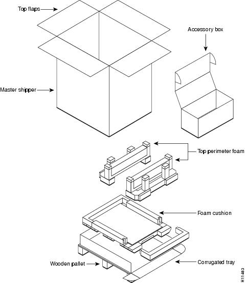
The Cisco 5814 dial shelf is a large, heavy chassis; it measures 19-in. (48.3 cm) wide, 21-in. (53.3 cm) deep, and 56-in. (142.2 cm) high. A fully configured dial shelf weighs approximately 278 lb (126.1 kg). In order to ship the chassis safely, a packaging kit has been engineered to prevent shock damage. This is the same packaging kit originally used to ship the dial shelf. If your original system packaging is damaged or was discarded, you must order a replacement packaging kit (PKG-5814=).
shows the dial shelf packaging detail.
Figure C-1 Cisco 5814 Packaging Detail
Required Tools and Parts
You will need the following tools and parts to remove the Cisco 5814 dial shelf components and to repackage the Cisco 5814 dial shelf:
•
Your own ESD-preventive wrist strap
•
•
•
•
•
•
•
•
•
•
•
Powering Off the Cisco AS5800
You must power off the Cisco AS5800 before attempting to dismantle the dial shelf for repackaging.
Powering off the access server involves the following components:
•
•
•
To power off the Cisco AS5800, follow these steps:
Warning
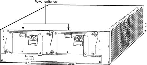
Step 1
Figure C-2 Router Shelf Power Switches
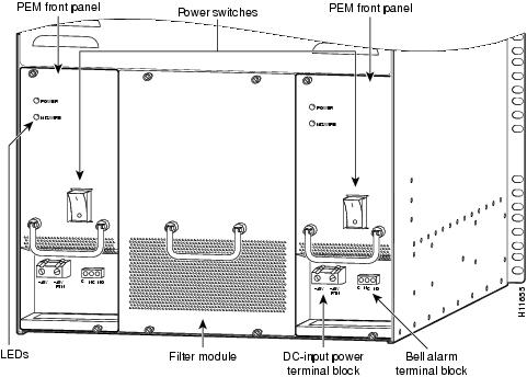
Step 2
Figure C-3 Dial Shelf Power Switches on the PEMS
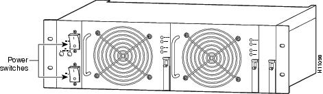
Step 3
Figure C-4 AC-Input Power Shelf
Step 4
Caution
Step 5
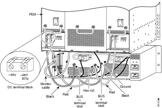
Figure C-5 PEM DC Terminal Block
Step 6
The last two steps refer to the optional AC-input power shelf. If you are using a DC power source, you can skip Step 7 and Step 8 and proceed to the section "Preparing to Repackage the Cisco 5814 Dial Shelf."
Step 7
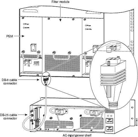
Figure C-6 Filter Module Monitor Cable DB-9 Connector
Step 8
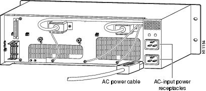
Figure C-7 AC-Input Power Shelf Cable Connections
.
Step 9
This completes the power-off sequence. Proceed to the following section, "Preparing to Repackage the Cisco 5814 Dial Shelf."
Preparing to Repackage the Cisco 5814 Dial Shelf
The Cisco 5814 dial shelf is equipped with a blower assembly, dial shelf cards (trunk and modem cards) and dial shelf controller cards configured in the chassis. Fully loaded, the dial shelf weighs 278 lb (126.1 kg).
Before removing the Cisco 5814 from the rack, we recommend that you remove the dial shelf cards, dial shelf controller cards, and the blower assembly from the dial shelf to decrease the chassis weight (see the "Removing the Blower Assembly" section and the "Removing Dial Shelf Cards and Dial Shelf Controller Cards" section), then reinstall the components (See the "Replacing the Dial Shelf Components" section) after the dial shelf is seated on the shipping pallet/base tray assembly.
Repackaging the Cisco 5814 Dial Shelf
To repackage the Cisco 5814 dial shelf, follow these steps:
Step 1
Step 2
Caution
Step 3
Step 4
Warning
Step 5
Step 6
Step 7
Step 8
Step 9
Step 10
Step 11
Step 12
The Cisco 5814 dial shelf is now packaged and ready to be transported. Use a forklift or pallet jack to move the dial shelf container.