Feedback
Table Of Contents
Background on Asynchronous Data Communications
Logical Packet and Circuit Components of a NAS
EIA/TIA-232 in Cisco IOS Software
Cisco IOS Line-Side Inspection
Understanding Modem Modulation Standards
Initiating a Modem Loopback Test Call
Initiating and Inspecting a V.90 Test Call
Configuring PPP and Authentication
Configuring PPP Authentication for Local AAA
Testing Asynchronous PPP Connections
Successful PPP Negotiation Debug
Failed PPP Negotiation Debugging and Troubleshooting
Fast Switching and Route Caching Statistics
Confirming the Final Running Configuration
Configuring Modems Using Modem Autoconfigure
Basic Rules for Modem Autoconfigure
Modem Autoconfigure K56Flex Example
Gathering and Viewing Call Statistics
Using the Cisco IOS EXEC (CLI)
Operations
This chapter details Cisco AS5800 routine operations performed on a daily basis to configure router interfaces.
In our discussion, local-based authentication is used. After the Cisco AS5800 hardware is commissioned, PPP is configured and tested as described in the section "Configuring PPP and Authentication" on page 25.
Verifying Modem Performance
This section describes how to verify and test modem performance on a Cisco AS5800 by using an EXEC terminal shell service.
The following sections are provided:
•
Background on Asynchronous Data Communications
•
•
•
An EXEC terminal shell service tests modem performance (lower layers) independently of PPP (and higher layers). A terminal-shell service test gets quick test results in a simple environment.
For information on how to manage modem pools and collect call statistics, see the "Modem Management Operations" section.
Background on Asynchronous Data Communications
Understanding how EIA/TIA-232 states function with the Cisco IOS software helps you test and troubleshoot modem connections:
•
•
•
Async DataComm Model
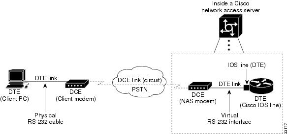
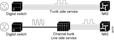
Figure 3-1 shows how traditional DTE-to-DCE relationships map to a Cisco network access server (NAS). Data terminal equipment (DTE) uses data communication equipment (DCE) to send data over the PSTN.
In the context of EIA/TIA-232 and Cisco IOS software:
•
•
•
•
Figure 3-1 A Standard Dialup Connection
Logical Packet and Circuit Components of a NAS
The NAS functions as a gateway between two different networks:
•
•
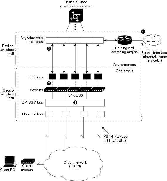
The NAS is half a circuit switch and half a packet switch (router). EIA/TIA-232 signaling on the line is displayed by the show line command and debug modem command. Figure 3-2 shows the modem access connectivity path.
Figure 3-2 Modem Access Connectivity Path
To understand the general call-processing sequence, match the following numbered list with the numbers shown in Figure 3-2:
1.
2.
3.
4.
EIA/TIA-232 in Cisco IOS Software
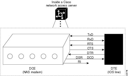
The Cisco IOS software variation of asynchronous EIA/TIA-232 is shown in Figure 3-3. The variation exists between the Cisco IOS line (DTE) and the NAS modem (DCE).
•
•
•
Figure 3-3 Cisco IOS EIA/TIA-232
Tips
Table 3-1 describes how Cisco uses its EIA/TIA-232 pins. The signal direction in the table is from the perspective of the DTE (IOS line):
•
•
•
Table 3-1 EIA/TIA-232 Signal State Behavior
Transmit Data (TxD)
——>
(Output)DTE transmits data to DCE.
Receive Data (RxD)
<——
(Input)DCE transmits received data to DTE.
Request To Send (RTS)
——>
(Output)DTE uses the RTS output signal to indicate if it can receive characters into the Rx input buffer1 .
The DCE should not send data to the DTE when DTR input is low (no RTS).
Clear To Send (CTS)
<——
(Input)DCE signals to DTE that it can continue to accept data into its buffers.
DCE asserts CTS only if the DCE is able to accept data.
Data Terminal Ready (DTR)
——>
(Output)DTE signals to DCE that it can continue to accept data into its buffers.
DTE asserts RTS only if the DTE is able to accept data.
Data Carrier Detect (DCD)
<——
(Input)DCE indicates to DTE that a call is established with a remote modem. Dropping DCD terminates the session.
DCD will be up on the DCE only if the DCE has achieved data mode with its peer DCE (client modem).
1 The name RTS is illogical with the function (able to receive) due to historical reasons.
Cisco IOS Line-Side Inspection
To display the current modem-hardware states applied to a specific Cisco IOS line, enter the show line tty number command. The states of each logical EIA/TIA-232 pin change according to line conditions and modem events.
The following shows a line-side inspection of the idle state for TTY line 1:
5800-NAS#show line tty 1Tty Typ Tx/Rx A Modem Roty AccO AccI Uses Noise Overruns IntI 1 TTY - inout - - - 2 0 0/0 -Line 1, Location:"", Type:""Length:24 lines, Width:80 columnsStatus:No Exit BannerCapabilities:Hardware Flowcontrol In, Hardware Flowcontrol OutModem Callout, Modem RI is CD, Line usable as async interfaceIntegrated ModemModem state:Idlemodem(slot/port)=1/0, state=IDLEdsx1(slot/unit/channel)=NONE, status=VDEV_STATUS_UNLOCKEDModem hardware state:CTS noDSR DTR RTSSpecial Chars:Escape Hold Stop Start Disconnect Activation^^x none - - noneTimeouts: Idle EXEC Idle Session Modem Answer Session Dispatch00:10:00 never none not setIdle Session Disconnect WarningneverLogin-sequence User Response00:00:30Autoselect Initial Waitnot setModem type is unknown.Session limit is not set.Time since activation:neverEditing is enabled.History is enabled, history size is 10.DNS resolution in show commands is enabledFull user help is disabledAllowed transports are pad telnet rlogin v120 lapb-ta. Preferred is telnet.No output characters are paddedNo special data dispatching charactersTable 3-2 describes some of the significant fields shown in the previous example:
Understanding Modem Modulation Standards
To optimize modem connect speeds, you must understand the basic modem modulation standards. This section provides the basic rules for achieving maximum V.34 and V.90 modulation speeds:
V.34 Basic Rules
V.34 modulation should work on any land-line voiceband circuit. V.34 supports speeds ranging from 2400 to 33600 bps.
Speed is a function of:
•
•
To achieve 33600 bps, the channel must deliver:
•
•
In practice, toll-quality voiceband circuits support V.34 at speeds of 21600 to 33600 bps.
The following six items reduce the achieved V.34 speed:
1.
2.
3.
4.
5.
–
–
–
–
–
6.
V.90 Basic Rules
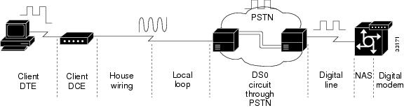
Many circuit components work together to deliver V.90 modulation. See Figure 3-4.
Figure 3-4 V.90 Network Components
Here are the V.90 basic rules:
•
–
–
•
Table 3-3 V.90 Supported Cisco IOS Releases
Cisco AS5800
MICA
11.3(6+)AA
12.0(1+)T
•
Figure 3-5 No Channel Banks for V.90
•
•
•
•
Initiating a Modem Loopback Test Call
Test the access server's ability to initiate and terminate a modem call. Similar to sending a ping to the next-hop router, this test verifies basic connectivity for modem operations. Successfully performing this test gives you a strong indication that remote clients should be able to dial into the NAS. Figure 3-6 shows this test.
After completing this test, dial into the EXEC from a client PC and a client modem (no PPP).
Figure 3-6 Initiating and Terminating a Modem Call on the Same NAS
Note
Step 1
Step 2
!line 1/2/00 1/3/143modem inouttransport input telnet!Step 3
5800-NAS#debug isdn q931ISDN Q931 packets debugging is on5800-NAS#debug csm modemModem Management Call Switching Module debugging is on5800-NAS#debug modemModem control/process activation debugging is on5800-NAS#show debugGeneral OS:Modem control/process activation debugging is onCSM Modem:Modem Management Call Switching Module debugging is onISDN:ISDN Q931 packets debugging is onISDN Q931 packets debug DSLs. (On/Off/No DSL:1/0/-)DSL 0 --> 311 - - - - - - - - - - - - - - - - - - - - - - - - - - - - - - -DSL 32 --> 55- - - - - - - - - - - - - - - - - - - - - - - -Modem Management:Modem Management Call Switching Module debugging is on5800-NAS#
Tips
5800-NAS(config)#service internal
5800-NAS(config)#end
5800-NAS#modem-mgmt csm debug-rbs
At the time of this publication, the Cisco AS5800 does not support the debug cas command or modem-mgmt csm debug-rbs command. As a workaround, complete the following steps:
a.
b.
c.
Step 4
5800-NAS#logging consoleStep 5
5800-NAS#telnet 172.22.66.23 2001Trying 172.22.66.23, 2001 ... Open
Note
For a Cisco AS5800, create an arbitrary IP host followed by a reverse Telnet. Use the show modem shelf/slot/port command to determine which modem is associated with which TTY line. The following example Telnets to TTY 500, which maps to modem 1/2/68.
5800-NAS#show modem 1/2/68Mdm Typ Status Tx/Rx G Duration RTS CTS DCD DTR--- --- ------ ----- - -------- --- --- --- ---1/2/68 V.90 Idle 37333/31200 1 00:01:05 RTS CTS noDCD DTRModem 1/2/68, Cisco MICA modem (Managed), Async1/2/68, TTY500Firmware Rev: 2.6.2.05800-NAS(config)#ip host mod500 2500 172.22.66.235800-NAS(config)#^Z5800-NAS#telnet mod500Trying mod500 (172.22.66.23, 2500)... OpenStep 6
This is a secured device.Unauthorized use is prohibited by law.User Access VerificationUsername:adminPassword:Sep 23 05:04:58.047: TTY0: pause timer type 1 (OK)Sep 23 05:04:58.051: TTY1: asserting DTRSep 23 05:04:58.051: TTY1: set timer type 10, 30 secondsSep 23 05:05:03.583: TTY1: set timer type 10, 30 secondsStep 7
atOKStep 8
atdt5551234CONNECT 33600 /V.42/V.42bisIn this example:
•
•
•
Step 9
000434: *May 2 23:01:39.507 UTC: ISDN Se1/0/0:23: RX <- SETUP pd = 8 callrefB000435: *May 2 23:01:39.507 UTC: Bearer Capability i = 0x9090A2000436: *May 2 23:01:39.507 UTC: Channel ID i = 0xA98381000437: *May 2 23:01:39.507 UTC: Progress Ind i = 0x8083 - Origination000438: *May 2 23:01:39.507 UTC: Calling Party Number i = 0x2183, '408'000439: *May 2 23:01:39.507 UTC: Called Party Number i = 0xC1, '324193'000440: *May 2 23:01:39.511 UTC: allocate slot 2 and port 12 is allocated000441: *May 2 23:01:39.511 UTC: ISDN Se1/0/0:23: TX -> CALL_PROC pd = 8 calB000442: *May 2 23:01:39.511 UTC: Channel ID i = 0xA98381000443: *May 2 23:01:39.511 UTC: CSM v(2/12) c(T1 1/0/0:0): CSM_EVENT_FROM_ISD.000444: *May 2 23:01:39.511 UTC: CSM v(2/12) c(T1 1/0/0:0): CSM_PROC_IDLE: ev.000445: *May 2 23:01:39.511 UTC: ISDN Se1/0/0:23: TX -> ALERTING pd = 8 callB000446: *May 2 23:01:39.539 UTC: CSM v(2/12) c(T1 1/0/0:0): CSM_PROC_IC2_RING:.000447: *May 2 23:01:39.539 UTC: ISDN Se1/0/0:23: TX -> CONNECT pd = 8 callrB000448: *May 2 23:01:39.563 UTC: ISDN Se1/0/0:23: RX <- CONNECT_ACK pd = 8 cB000449: *May 2 23:01:39.563 UTC: ISDN Se1/0/0:23: CALL_PROGRESS: CALL_CONNECTE0000450: *May 2 23:01:39.563 UTC: CSM v(2/12) c(T1 1/0/0:0): CSM_EVENT_FROM_ISD.000451: *May 2 23:01:39.563 UTC: CSM v(2/12) c(T1 1/0/0:0): CSM_PROC_IC6_WAIT_.000452: *May 2 23:01:57.778 UTC: TTY1/2/12: DSR came up000453: *May 2 23:01:57.778 UTC: tty1/2/12: Modem: IDLE->(unknown)000454: *May 2 23:01:57.778 UTC: TTY1/2/12: EXEC creation000455: *May 2 23:01:57.778 UTC: TTY1/2/12: create timer type 1, 600 seconds000456: *May 2 23:02:05.462 UTC: TTY1/2/12: set timer type 10, 30 seconds
Note
The bearer capability 0x8090A2 indicates an analog voice call. Alternative bearer services include 64K data calls, which are indicated by 0x8890. The calling party number is 408 (also known as ANI). The called party number is 5551234 (also known as DNIS). The debug q931 command shows the call coming into the NAS over ISDN.
*Jan 1 00:34:47.867:VDEV_ALLOCATE:1/2 is allocated from pool System-def-Mpool*Jan 1 00:34:47.867:csm_get_vdev_for_isdn_call:fax_call=0*Jan 1 00:34:47.867:EVENT_FROM_ISDN:(001A):DEV_INCALL at slot 1 and port 2*Jan 1 00:34:47.867:CSM_PROC_IDLE:CSM_EVENT_ISDN_CALL at slot 1, port 2*Jan 1 00:34:47.867:Mica Modem(1/2):Configure(0x1 = 0x0)*Jan 1 00:34:47.867:Mica Modem(1/2):Configure(0x23 = 0x0)*Jan 1 00:34:47.867:Mica Modem(1/2):Call Setup*Jan 1 00:34:47.867: Enter csm_connect_pri_vdev function*Jan 1 00:34:47.867:csm_connect_pri_vdev:tdm_allocate_bp_ts() call. BP TS allocated at bp_stream0, bp_Ch5,vdev_common 0x610378B0*Jan 1 00:34:47.883:ISDN Se0:23:RX <- ALERTING pd = 8 callref = 0x8004*Jan 1 00:34:47.883: Progress Ind i = 0x8288 - In-band info or appropriate now available*Jan 1 00:34:48.019:Mica Modem(1/2):State Transition to Call Setup*Jan 1 00:34:48.019:Mica Modem(1/2):Went offhook*Jan 1 00:34:48.019:CSM_PROC_IC2_RING:CSM_EVENT_MODEM_OFFHOOK at slot 1, port 2*Jan 1 00:34:48.019:ISDN Se0:23:TX -> CONNECT pd = 8 callref = 0x8053*Jan 1 00:34:48.047:ISDN Se0:23:RX <- CONNECT_ACK pd = 8 callref = 0x0053*Jan 1 00:34:48.047:EVENT_FROM_ISDN::dchan_idb=0x6149A144, call_id=0x1A, ces=0x1 bchan=0x0, event=0x4, cause=0x0*Jan 1 00:34:48.047:EVENT_FROM_ISDN:(001A):DEV_CONNECTED at slot 1 and port 2*Jan 1 00:34:48.047:CSM_PROC_IC4_WAIT_FOR_CARRIER:CSM_EVENT_ISDN_CONNECTED at slot 1, port 2*Jan 1 00:34:48.047:Mica Modem(1/2):Link Initiate*Jan 1 00:34:48.047:ISDN Se0:23:RX <- CONNECT pd = 8 callref = 0x8004*Jan 1 00:34:48.047:EVENT_FROM_ISDN::dchan_idb=0x6149A144, call_id=0x8005, ces=0x1 bchan=0x16, event=0x4, cause=0x0*Jan 1 00:34:48.047:EVENT_FROM_ISDN:(8005):DEV_CONNECTED at slot 1 and port 0*Jan 1 00:34:48.047:CSM_PROC_OC5_WAIT_FOR_CARRIER:CSM_EVENT_ISDN_CONNECTED at slot 1, port 0*Jan 1 00:34:48.051:ISDN Se0:23:TX -> CONNECT_ACK pd = 8 callref = 0x0004MICA modem 1/2 goes offhook and receives the call. The debug modem csm command shows the call getting switched over to a modem.
*Jan 1 00:34:49.159:Mica Modem(1/2):State Transition to Connect*Jan 1 00:34:53.903:Mica Modem(1/2):State Transition to Link*Jan 1 00:35:02.851:Mica Modem(1/2):State Transition to Trainup*Jan 1 00:35:04.531:Mica Modem(1/2):State Transition to EC Negotiating*Jan 1 00:35:04.711:Mica Modem(1/2):State Transition to Steady State*Jan 1 00:35:04.755:TTY3:DSR came up*Jan 1 00:35:04.755:tty3:Modem:IDLE->(unknown)Inspect the different modem trainup phases. The modem goes from Connect to Steady State in 15 seconds. The debug modem csm command displays the trainup phases. The debug modem command displays the logical EIA/TIA-232 transition message "DSR came up."
*Jan 1 00:35:04.759:TTY3:EXEC creation*Jan 1 00:35:04.759:TTY3:set timer type 10, 30 seconds*Jan 1 00:35:08.915:TTY3:Autoselect(2) sample 61 <------------------- a*Jan 1 00:35:09.187:TTY3:Autoselect(2) sample 6164 <----------------- d*Jan 1 00:35:09.459:TTY3:Autoselect(2) sample 61646D <--------------- m*Jan 1 00:35:09.459:TTY3:Autoselect(2) sample 61646D69 <------------- i*Jan 1 00:35:09.715:TTY3:Autoselect(2) sample 646D696E <------------- n*Jan 1 00:35:09.715:TTY3:Autoselect(2) sample 6D696E0D <------------- <cr>Decode the incoming character-byte stream for an EXEC shell login (no PPP). In this example, match the username "admin" to the character stream: 616D696E0D = admin carriage return.
The Cisco IOS samples four packets at a time. It searches for a header that matches one of your autoselect styles. The debug modem command generates the autoselect debug output.
*Jan 1 00:35:09.715:TTY3:set timer type 10, 30 seconds*Jan 1 00:35:11.331:TTY3:Autoselect(2) sample [suppressed--line is not echoing]*Jan 1 00:35:11.667:TTY3:Autoselect(2) sample [suppressed--line is not echoing]*Jan 1 00:35:11.987:TTY3:Autoselect(2) sample [suppressed--line is not echoing]*Jan 1 00:35:11.987:TTY3:Autoselect(2) sample [suppressed--line is not echoing]*Jan 1 00:35:11.987:TTY3:Autoselect(2) sample [suppressed--line is not echoing]*Jan 1 00:35:12.339:TTY3:Autoselect(2) sample [suppressed--line is not echoing]*Jan 1 00:35:12.391:TTY3:create timer type 1, 600 seconds5800-NAS>Type 10 is the login timer. The timeout is 30 seconds. The user's EXEC-shell login password is suppressed.
Step 10
5800-NAS> show userLine User Host(s) Idle Location3 tty 3 admin idle 0* 98 vty 0 joe 172.22.66.1 0 leftfield.corporate.comInterface User Mode Idle Peer Addressd.
5800-NAS> terminal length 0Step 11
5800-NAS> show modem logdoc-rtr58-01#sh modem logModem 1/2/00 Events Log:3w2d :Startup event:MICA Hex modem (Managed)Modem firmware = 0.7.3.72w2d :Modem State event:State:Terminate2w2d :Modem State event:State:IdleModem 1/2/01 Events Log:3w2d :Startup event:MICA Hex modem (Managed)Modem firmware = 0.7.3.72w2d :Modem State event:State:Terminate2w2d :Modem State event:State:IdleModem 1/2/02 Events Log:3w2d :Startup event:MICA Hex modem (Managed)Modem firmware = 0.7.3.72w2d :Modem State event:State:Terminate2w2d :Modem State event:State:IdleStep 12
If you do not have a scroll bar in your Telnet application, limit terminal length to 24 lines to see all the command output.
If you are using Microcom modems, enter the modem at-mode slot/port command followed by the at@e1 command.
5800-NAS> show modem operational-status 1/2/00Modem(1/2/00) Operational-Status:Parameter #0 Disconnect Reason Info: (0x0)Type (=0 ): <unknown>Class (=0 ): OtherReason (=0 ): no disconnect has yet occurredParameter #1 Connect Protocol: LAP-MParameter #2 Compression: V.42bis bothParameter #3 EC Retransmission Count: 0Parameter #4 Self Test Error Count: 0Parameter #5 Call Timer: 597 secsParameter #6 Total Retrains: 0Parameter #7 Sq Value: 4Parameter #8 Connected Standard: V.34+Parameter #9 TX,RX Bit Rate: 33600, 33600Parameter #11 TX,RX Symbol Rate: 3429, 3429Parameter #13 TX,RX Carrier Frequency: 1959, 1959Parameter #15 TX,RX Trellis Coding: 16, 16Parameter #16 TX,RX Preemphasis Index: 0, 0Parameter #17 TX,RX Constellation Shaping: Off, OffParameter #18 TX,RX Nonlinear Encoding: Off, OffParameter #19 TX,RX Precoding: Off, OffParameter #20 TX,RX Xmit Level Reduction: 0, 0 dBmParameter #21 Signal Noise Ratio: 41 dBParameter #22 Receive Level: -12 dBmParameter #23 Frequency Offset: 0 HzParameter #24 Phase Jitter Frequency: 0 HzParameter #25 Phase Jitter Level: 0 degreesParameter #26 Far End Echo Level: -52 dBmParameter #27 Phase Roll: 31 degreesParameter #28 Round Trip Delay: 1 msecsParameter #30 Characters transmitted, received: 70966, 80Parameter #32 Characters received BAD: 2Parameter #33 PPP/SLIP packets transmitted, received: 0, 0Parameter #35 PPP/SLIP packets received (BAD/ABORTED): 0Parameter #36 EC packets transmitted, received OK: 269, 61Parameter #38 EC packets (Received BAD/ABORTED): 0Parameter #39 Robbed Bit Signalling (RBS) pattern: 0Parameter #40 Digital Pad: None, Digital Pad Compensation:NoneLine Shape:..............................*................................*.................................*................................*................................*.................................*.................................*.................................*................................*.................................*.................................*................................*................................*................................*................................*................................*................................*................................*.................................*Table 3-4 describes the significant parameters in the previous example. For a complete command reference description, refer to Modem Management Commands, available online at
http://www.cisco.com/univercd/cc/td/doc/product/software/ios120/12cgcr/dial_r/drprt1/
Step 13
5800-NAS# undebug allAll possible debugging has been turned off
Initiating and Inspecting a V.90 Test Call
Before you let users dial in to the NAS, initiate and inspect a V.90 test call. V.90 call performance is heavily dependent upon the telco's network topology. There are many variables.
Most modem manufactures have unique AT command sets. The AT commands used in the following procedure may not be supported by your modem. For more information, refer to the following:
•
http://56k.com/links/Modem_Manuals/•
http://808hi.com/56k/trouble1.htm
Step 1
Step 2
atOKStep 3
The ati3 and ati7 modem firmware commands are commonly used and are shown below:
ati3U.S. Robotics 56K FAX EXT V4.11.2OKati7Configuration Profile...Product type US/Canada ExternalProduct ID: 00568602Options V32bis,V.34+,x2,V.90Fax Options Class 1/Class 2.0Line Options Caller ID, Distinctive RingClock Freq 92.0MhzEPROM 256kRAM 32kFLASH date 6/3/98FLASH rev 4.11.2DSP date 6/3/98DSP rev 4.11.2OKStep 4
ati4U.S. Robotics 56K FAX EXT Settings...B0 E1 F1 M1 Q0 V1 X1 Y0BAUD=38400 PARITY=N WORDLEN=8DIAL=TONE ON HOOK CID=0&A1 &B1 &C1 &D2 &G0 &H0 &I0 &K0&M4 &N0 &P0 &R1 &S0 &T5 &U0 &Y1S00=000 S01=000 S02=043 S03=013 S04=010 S05=008 S06=002S07=060 S08=002 S09=006 S10=014 S11=070 S12=050 S13=000S15=000 S16=000 S18=000 S19=000 S21=010 S22=017 S23=019S25=005 S27=000 S28=008 S29=020 S30=000 S31=128 S32=002S33=000 S34=000 S35=000 S36=014S38=000 S39=000 S40=001S41=000 S42=000LAST DIALED #: T14085551234OKStep 5
atdt14085551234CONNECT 48000/ARQThis is a secured device.Unauthorized use is prohibited by law.User Access VerificationUsername:userPassword:5800-NAS>Step 6
5800-NAS> show callerActive IdleLine User Service Time Timevty 0 - VTY 00:07:46 00:00:005800-NAS> show caller
Note
Step 7
5800-NAS> show terminalLine 1/2/10, Location: "", Type: ""Length: 24 lines, Width: 80 columnsStatus: PSI Enabled, Ready, Active, No Exit BannerCapabilities: Hardware Flowcontrol In, Hardware Flowcontrol OutModem Callout, Modem RI is CDModem state: ReadyModem hardware state: CTS DSR DTR RTSmodem=1/2/10, vdev_state(0x00000000)=CSM_OC_STATE, bchan_num=(T1 1/0/0:0)vdev_status(0x00000001): VDEV_STATUS_ACTIVE_CALL.Group codes: 0Special Chars: Escape Hold Stop Start Disconnect Activation^^x none - - noneTimeouts: Idle EXEC Idle Session Modem Answer Session Dispatch00:10:00 never none not setIdle Session Disconnect WarningneverLogin-sequence User Response00:00:30Autoselect Initial Waitnot setModem type is unknown.Session limit is not set.Time since activation: 00:12:24Editing is enabled.History is enabled, history size is 10.DNS resolution in show commands is enabledFull user help is disabledAllowed transports are lat pad v120 telnet rlogin dsipcon. Preferred is lat.No output characters are paddedNo special data dispatching charactersStep 8
5800-NAS> terminal length 0Step 9
5800-NAS> show modem logModem 1/2/00 Events Log:3w4d :Startup event:MICA Hex modem (Managed)Modem firmware = 2.7.1.03w4d :RS232 event: noRTS, noDTR, CTS, noDCD3w4d :RS232 event: noRTS, DTR, CTS, noDCDThe output generated by the show modem log command sends a large data stream across the modem link - about 1 MB of data. The data should scroll freely for one or two minutes.
Step 10
5800-NAS> show modem operational-status 1/2/00Modem(1/2/00) Operational-Status:Parameter #0 Disconnect Reason Info: (0x0)Type (=0 ): <unknown>Class (=0 ): OtherReason (=0 ): no disconnect has yet occurredParameter #1 Connect Protocol: LAP-MParameter #2 Compression: NoneParameter #3 EC Retransmission Count: 2Parameter #4 Self Test Error Count: 0Parameter #5 Call Timer: 118 secsParameter #6 Total Retrains: 0Parameter #7 Sq Value: 3Parameter #8 Connected Standard: V.90Parameter #9 TX,RX Bit Rate: 48000, 28800Parameter #11 TX,RX Symbol Rate: 8000, 3200Parameter #13 TX,RX Carrier Frequency: 0, 1920Parameter #15 TX,RX Trellis Coding: 0, 16Parameter #16 TX,RX Preemphasis Index: 0, 6Parameter #17 TX,RX Constellation Shaping: Off, OffParameter #18 TX,RX Nonlinear Encoding: Off, OffParameter #19 TX,RX Precoding: Off, OffParameter #20 TX,RX Xmit Level Reduction: 0, 0 dBmParameter #21 Signal Noise Ratio: 36 dBParameter #22 Receive Level: -19 dBmParameter #23 Frequency Offset: 0 HzParameter #24 Phase Jitter Frequency: 0 HzParameter #25 Phase Jitter Level: 0 degreesParameter #26 Far End Echo Level: -37 dBmParameter #27 Phase Roll: 0 degreesParameter #28 Round Trip Delay: 23 msecsParameter #30 Characters transmitted, received: 67109, 43Parameter #32 Characters received BAD: 0Parameter #33 PPP/SLIP packets transmitted, received: 0, 0Parameter #35 PPP/SLIP packets received (BAD/ABORTED): 0Parameter #36 EC packets transmitted, received OK: 565, 43Parameter #38 EC packets (Received BAD/ABORTED): 2Parameter #39 Robbed Bit Signalling (RBS) pattern: 0Parameter #40 Digital Pad: 6.0 dB, Digital Pad Compensation:NoneLine Shape:.........................*................................*.................................*.................................*................................*.................................*.................................*.................................*................................*................................*................................*................................*................................*................................*................................*................................*................................*Table 3-5 describes the significant output fields (bold font) in the previous example:
Step 11
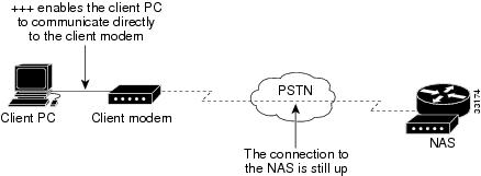
5800-NAS>+++OKatOKIn the example, the client modem reports both "OK" messages. The +++ modem-escape sequence is similar to a router's Telnet-escape mode (Shift + Ctrl + 6 + x). See Figure 3-7.
Figure 3-7 Using Modem-Escape Mode to View Client-Side Modem Statistics
Step 12
If ati6 is not supported by your modem, try at&v1. For additional client report statistics, enable Windows modemlog.txt or ppplog.txt files.
ati6U.S. Robotics 56K FAX EXT Link Diagnostics...Chars sent 98 Chars Received 104701Chars lost 0Octets sent 354 Octets Received 104701Blocks sent 95 Blocks Received 914Blocks resent 4Retrains Requested 0 Retrains Granted 0Line Reversals 0 Blers 0Link Timeouts 0 Link Naks 1Data Compression NONEEqualization LongFallback EnabledProtocol LAPMSpeed 48000/28800V.90 Peak Speed 48000Current Call 00:04:46OnlineOK
Step 13
aty11Freq Level (dB)150 24300 23450 22600 22750 22900 221050 221200 221350 221500 221650 221800 231950 232100 232250 232400 232550 232700 232850 233000 233150 233300 243450 253600 273750 31ati11U.S. Robotics 56K FAX EXT Link Diagnostics...Modulation V.90Carrier Freq (Hz) None/1920Symbol Rate 8000/3200Trellis Code None/64S-4DNonlinear Encoding None/ONPrecoding None/ONShaping ON/ONPreemphasis (-dB) 6/2Recv/Xmit Level (-dBm) 19/10Near Echo Loss (dB) 7Far Echo Loss (dB) 0Carrier Offset (Hz) NONERound Trip Delay (msec) 24Timing Offset (ppm) 1638SNR (dB) 48.1Speed Shifts Up/Down 0/0Status : uu,5,13Y,19.4,-15,1N,0,51.1,7.3OKStep 14
ato% Unknown command or computer name, or unable to find computer address5800-NAS>
Configuring PPP and Authentication
This section describes how to configure the Cisco AS5800 for PPP and local authentication.
The following sections are provided:
•
•
•
•
After local authentication is verified, use TACACS+ and a remote authentication server or RADIUS.
Configuring PPP Authentication for Local AAA
Configure AAA to perform log in authentication by using the local username database. The login keyword authenticates EXEC terminal shell users. Additionally, configure PPP authentication to use the local database if the session was not already authenticated by login.
Step 1
!username admin password adminpassusername theuser password theuserpass!Warning
Step 2
!aaa new-modelaaa authentication login default localaaa authentication ppp default if-needed local!Step 3
5800-NAS# loginThis is a secured device.Unauthorized use is prohibited by law.User Access VerificationUsername: theuserPassword:5800-NAS#
Caution
Configuring IPCP Options
Create a pool of IP addresses to assign to the PC clients dialing in. As the clients connect, they request IP addresses from the NAS.
Tips
Step 1
!ip local pool addr-pool 172.22.90.2 172.22.90.254!async-bootp dns-server 172.30.10.1 172.30.10.2!For clients using server-assigned addressing (if there are any) you must specify primary and secondary DNS servers. The clients send config-requests to the NAS if the clients are configured to receive NAS assigned WINS and DNS servers.
Note
Step 2
5800-NAS# show ip local poolPool Begin End Free In useaddr-pool 172.22.90.2 172.22.90.254 253 05800-NAS#
Configuring LCP Options
The group-async interface is a template that controls the configuration of all the asynchronous interfaces in the NAS.
Asynchronous interfaces:
•
•
•
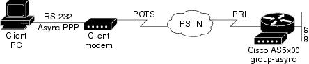
The client PPP framing must match the Cisco IOS interface. Figure 3-8 shows this concept.
Figure 3-8 Modem Dialup PPP Framing
The following group-async configuration applies to asynchronous interfaces 1/2/00 through 1/10/143:
!interface Group-Async0ip unnumbered FastEthernet0/1/0encapsulation pppasync mode interactiveppp authentication chap pappeer default ip address pool addr-poolno cdp enableno ip directed-broadcastgroup-range 1/2/00 1/10/143!Table 3-6 describes the previous configuration snippet in more detail:
Enabling PPP Autoselect
Enable remote PPP users to dial in, bypass the EXEC facility, and automatically start PPP on the line.
!line 1/2/00 1/10/143autoselect during-loginautoselect ppp!These two autoselect commands:
•
•
Note
Testing Asynchronous PPP Connections
Before you troubleshoot PPP negotiation or AAA authentication, you need to understand what a successful PPP and AAA debug sequence looks like. In this way, you can save time and effort when comparing a successful debug session against a faulty completed debug sequence.
Successful PPP Negotiation Debug
The following steps describe how to initiate a PPP test call and interpret a successful debug sequence.
Step 1
5800-NAS# debug ppp authenticationPPP authentication debugging is on5800-NAS# debug aaa authenticationAAA Authentication debugging is on5800-NAS# show debugGeneral OS:AAA Authentication debugging is onPPP:PPP authentication debugging is onStep 2
5800-NAS# logging consoleStep 3
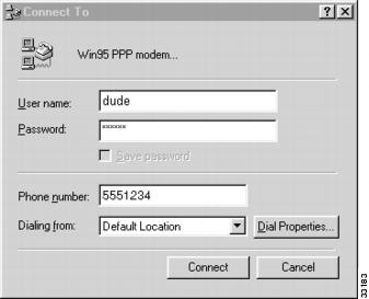
Figure 3-9 Windows Dialup Networking
Step 4
When examining PPP between two remote peers:
a.
b.
c.
d.
Given the debug commands entered in Step 1, the following debug output should be generated by the call:
*Sep 24 13:05:49.052: AAA: parse name=tty1/2/09 idb type=10 tty=441*Sep 24 13:05:49.052: AAA: name=tty1/2/09 flags=0x1D type=4 shelf=0 slot=1 adapter=2 port=9 channel=0*Sep 24 13:05:49.052: AAA: parse name=Serial1/0/0:4:21 idb type=12 tty=-1*Sep 24 13:05:49.052: AAA: name=Serial1/0/0:4:21 flags=0x5D type=1 shelf=0 slot=1 adapter=0 port=4 channel=21In this example, the call enters the NAS on channel 1/0/0:4:21. This channel maps to the 21st DS0 channel of the 4th PRI line of a CT3 card. Eventually the call terminates on modem 441.
*Sep 24 13:05:49.052: AAA/MEMORY: create_user (0x63E8FB70) user='' ruser='' port
='tty1/2/09' rem_addr='4089548211/51121' authen_type=ASCII service=LOGIN priv=1
*Sep 24 13:05:49.052: AAA/AUTHEN/START (1586904428): port='tty1/2/09' list='' ac tion=LOGIN service=LOGIN*Sep 24 13:05:49.052: AAA/AUTHEN/START (1586904428): using "default" list*Sep 24 13:05:49.052: AAA/AUTHEN/START (1586904428): Method=LOCAL*Sep 24 13:05:49.052: AAA/AUTHEN (1586904428): status = GETUSER*Sep 24 13:05:49.072: AAA/AUTHEN/ABORT: (1586904428) because Autoselected.*Sep 24 13:05:49.072: AAA/MEMORY: free_user (0x63E8FB70) user='' ruser='' port='An authentication start packet is sent by AAA, and it searches the local username database as the default authentication method.
tty1/2/09' rem_addr='4089548211/51121' authen_type=ASCII service=LOGIN priv=1*Sep 24 13:05:51.076: As1/2/09 PPP: Treating connection as a dedicated line*Sep 24 13:05:55.272: As1/2/09 PPP: Phase is AUTHENTICATING, by this end*Sep 24 13:05:55.404: As1/2/09 PAP: I AUTH-REQ id 1 len 20 from "theuser"*Sep 24 13:05:55.404: As1/2/09 PAP: Authenticating peer theuserPPP is allowed to start on the interface. The client sends an authentication request called theuser. PAP authentication is used.
*Sep 24 13:05:55.404: AAA: parse name=Async1/2/09 idb type=10 tty=441*Sep 24 13:05:55.404: AAA: name=Async1/2/09 flags=0x1D type=4 shelf=0 slot=1 adapter=2 port=9 channel=0*Sep 24 13:05:55.404: AAA: parse name=Serial1/0/0:4:21 idb type=12 tty=-1*Sep 24 13:05:55.404: AAA: name=Serial1/0/0:4:21 flags=0x5D type=1 shelf=0 slot=1 adapter=0 port=4 channel=21*Sep 24 13:05:55.404: AAA/MEMORY: create_user (0x63E8FB70) user='theuser' ruser=''port='Async1/2/09' rem_addr='4089548211/51121' authen_type=PAP service=PPP priv=1*Sep 24 13:05:55.404: AAA/AUTHEN/START (693233173): port='Async1/2/09' list='' action=LOGIN service=PPP*Sep 24 13:05:55.404: AAA/AUTHEN/START (693233173): using "default" list*Sep 24 13:05:55.404: AAA/AUTHEN (693233173): status = UNKNOWN*Sep 24 13:05:55.404: AAA/AUTHEN/START (693233173): Method=LOCAL*Sep 24 13:05:55.404: AAA/AUTHEN (693233173): status = PASS*Sep 24 13:05:55.404: As1/2/09 PAP: O AUTH-ACK id 1 len 5The example above shows that local authentication was successful.
Failed PPP Negotiation Debugging and Troubleshooting
Failed authentication is a common occurrence. Misconfigured or mismatched user names and passwords create error messages in debug output.
The following example shows that the username maddog does not have permission to dial into the NAS. The NAS does not have a local username configured for this user. To fix the problem, use the username name password password command to add the username to the local AAA database in the NAS:
*Sep 24 13:11:28.964: AAA/MEMORY: create_user (0x63E43558) user='maddog' ruser=''
port='Async1/2/10' rem_addr='4089548211/51121' authen_type=PAP service=PPP priv=1
*Sep 24 13:11:28.964: AAA/AUTHEN/START (3281080218): port='Async1/2/10' list=''action=LOGIN service=PPP*Sep 24 13:11:28.964: AAA/AUTHEN/START (3281080218): using "default" list*Sep 24 13:11:28.964: AAA/AUTHEN (3281080218): status = UNKNOWN*Sep 24 13:11:28.964: AAA/AUTHEN/START (3281080218): Method=LOCAL*Sep 24 13:11:28.964: AAA/AUTHEN (3281080218): User not found, end of method list*Sep 24 13:11:28.964: AAA/AUTHEN (3281080218): status = FAIL*Sep 24 13:11:28.964: As1/2/10 PAP: O AUTH-NAK id 1 len 32 msg is "Password validation failure"*Sep 24 13:11:28.964: AAA/MEMORY: free_user (0x63E43558) user='maddog' ruser=''port='Async1/2/10' rem_addr='4089548211/51121' authen_type=PAP service=PPP priv=1The following example shows an invalid password. Notice that the same error messages are used for username failure—"Password validation failure."
*Sep 24 13:13:59.032: AAA/MEMORY: create_user (0x63E9846C) user='user'
ruser=''port='Async1/2/11' rem_addr='4089548211/51121' authen_type=PAP service=PPP priv=1
*Sep 24 13:13:59.032: AAA/AUTHEN/START (3032205297): port='Async1/2/11' list=''action=LOGIN service=PPP*Sep 24 13:13:59.032: AAA/AUTHEN/START (3032205297): using "default" list*Sep 24 13:13:59.032: AAA/AUTHEN (3032205297): status = UNKNOWN*Sep 24 13:13:59.032: AAA/AUTHEN/START (3032205297): Method=LOCAL*Sep 24 13:13:59.032: AAA/AUTHEN (3032205297): status = FAIL*Sep 24 13:13:59.032: As1/2/11 PAP: O AUTH-NAK id 1 len 32 msg is "Password validation failure"*Sep 24 13:13:59.036: AAA/MEMORY: free_user (0x63E9846C) user='user' ruser='' port='Async1/2/11' rem_addr='4089548211/51121' authen_type=PAP service=PPP priv=1Troubleshooting Flow Diagrams
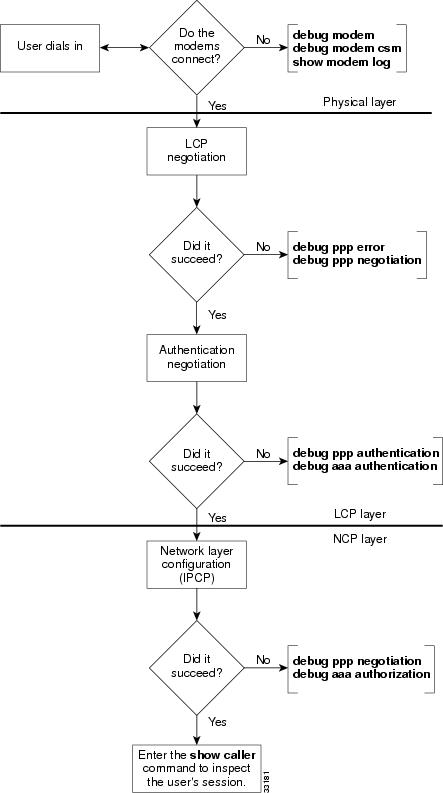
Figure 3-10 provides a flowchart for troubleshooting the following three PPP layers:
•
•
•
Figure 3-10 Troubleshooting Flow Chart for PPP and Authentication
LCP negotiation is a series of LCP packets exchanged between PPP peers to negotiate a set of options and option values when sending data. The LCP negotiation is actually two separate dialogs between two PPP peers (Peer1 and Peer 2):
Peer 1 and Peer 2 do not have to use the same set of LCP options. When a PPP peer sends its initial Configure-Request, the response is any of the following:
•
•
•
When a PPP peer receives a Configure-Nack or Configure-Reject in response to its Configure-Request, it sends a new Configure-Request with modified options or option values. When a Configure-Ack is received, the PPP peer is ready to send data.
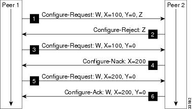
Figure 3-11 shows an example LCP negotiation process for Peer 1 using the fictional options W, X, Y, Z. Additionally, Figure 3-11 shows Peer 1 sending data to Peer 2 only. Separate LCP negotiation must be configured so that Peer 2 can send data back to Peer 1. Very often, the LCP packets for both Peer 1 and Peer 2 are intermixed during the connection process (that is, Peer 1 is configuring the way it sends data at the same time as Peer 2.).
Figure 3-11 LCP Layer Negotiations
Figure 3-11 shows that:
•
•
•
•
•
•
Each time Peer 1 sends a new Configure-Request, it changes the Identifier value in the LCP header so that Configure-Requests can be matched with their responses.
Inspecting Active Call States
After a basic PPP modem call comes into the NAS, you should use some show commands to inspect several active call statistics. If you try to use the client's web browser after the modems connect, you will test DNS, IP, and other functions. If your test fails, try pinging the DNS server from the device that dialed in.
Show Caller Statistics
The show caller command is used to:
•
•
•
The show caller command has many options:
5800-NAS# show caller ?full Provide expanded caller informationinterface Provide information on one interfaceip Display IP informationline Provide information on one linetimeouts Display session and idle limits and disconnect timeuser Display information for a particular user| Output modifiers<cr>5800-NAS# show callerActive IdleLine User Service Time Timevty 0 admin VTY 00:54:39 00:00:00tty 441 theuser Async 00:00:15 00:00:00As1/2/09 theuser PPP 00:00:08 00:00:005800-NAS# show caller user theuserUser: theuser, line tty 441, service AsyncActive time 00:01:24, Idle time 00:01:05Timeouts: Absolute Idle IdleSession ExecLimits: - - 00:10:00Disconnect in: - - -TTY: Line 1/2/09, running PPP on As1/2/09Location: PPP: 192.168.10.4DS0: (slot/unit/channel)=0/4/21Status: Ready, Active, No Exit Banner, Async Interface ActiveHW PPP Support Active, Modem DetectedCapabilities: Hardware Flowcontrol In, Hardware Flowcontrol OutModem Callout, Modem RI is CD,Line usable as async interface, Modem AutoconfigureModem State: Ready, Modem ConfiguredUser: theuser, line As1/2/09, service PPPActive time 00:01:17, Idle time 00:01:05Timeouts: Absolute IdleLimits: - -Disconnect in: - -PPP: LCP Open, PAP (<- AAA), IPCPIP: Local 172.22.66.23, remote 172.22.90.2Counts: 30 packets input, 1640 bytes, 0 no buffer1 input errors, 1 CRC, 0 frame, 0 overrun14 packets output, 290 bytes, 0 underruns0 output errors, 0 collisions, 0 interface resetsIn the previous example, notice that one call uses the following system resources:
•
•
•
•
Note
Table 3-7 describes some of the significant display output fields of the show caller user command:
Fast Switching and Route Caching Statistics
Inspect fast-switching and route-caching performance statistics for the call. Incoming asynchronous calls can be fast switched. However, some features disable fast switching.
Step 1
5800-NAS# show interface async 1/2/02Async1/2/02 is up, line protocol is upmodem=1/2/02, vdev_state(0x00000000)=CSM_OC_STATE, bchan_num=(T1 1/0/0:4:6)vdev_status(0x00000001): VDEV_STATUS_ACTIVE_CALL.Hardware is Async SerialInterface is unnumbered. Using address of FastEthernet0/1/0 (172.22.66.23)MTU 1500 bytes, BW 9 Kbit, DLY 100000 usec,reliability 255/255, txload 1/255, rxload 1/255Encapsulation PPP, loopback not set, keepalive not setDTR is pulsed for 5 seconds on resetLCP OpenOpen: IPCPLast input 00:00:00, output 00:00:00, output hang neverLast clearing of "show interface" counters neverQueueing strategy: fifoOutput queue 0/10, 0 drops; input queue 1/10, 0 drops5 minute input rate 0 bits/sec, 1 packets/sec5 minute output rate 0 bits/sec, 1 packets/sec1683 packets input, 112764 bytes, 0 no bufferReceived 0 broadcasts, 0 runts, 0 giants, 0 throttles1 input errors, 1 CRC, 0 frame, 0 overrun, 0 ignored, 0 abort1626 packets output, 108235 bytes, 0 underruns0 output errors, 0 collisions, 0 interface resets0 output buffer failures, 0 output buffers swapped out0 carrier transitionsStep 2
5800-NAS# show ip int async 1/2/02Async1/2/02 is up, line protocol is upInterface is unnumbered. Using address of FastEthernet0/1/0 (172.22.66.23)Broadcast address is 255.255.255.255Peer address is 172.22.90.2MTU is 1500 bytesHelper address is not setDirected broadcast forwarding is enabledOutgoing access list is not setInbound access list is not setProxy ARP is enabledSecurity level is defaultSplit horizon is enabledICMP redirects are always sentICMP unreachables are always sentICMP mask replies are never sentIP fast switching is disabledIP fast switching on the same interface is disabledIP multicast fast switching is enabledRouter Discovery is disabledIP output packet accounting is disabledIP access violation accounting is disabledTCP/IP header compression is enabled and compressingRTP/IP header compression is disabledProbe proxy name replies are disabledGateway Discovery is disabledPolicy routing is disabledNetwork address translation is disabledStep 3
5800-NAS# show ip cacheIP routing cache 3 entries, 560 bytes109 adds, 106 invalidates, 3 refcountsMinimum invalidation interval 2 seconds, maximum interval 5 seconds,quiet interval 3 seconds, threshold 0 requestsInvalidation rate 0 in last second, 0 in last 3 secondsLast full cache invalidation occurred 22:17:01 agoPrefix/Length Age Interface Next Hop172.61.0.0/16 15:13:22 FastEthernet0/1 172.22.66.1172.22.67.67/32 00:06:10 FastEthernet0/1 172.22.67.2172.22.68.67/32 00:06:09 FastEthernet0/1 172.22.68.35800-NAS# show interface async 1/2/02 statAsync1/2/02Switching path Pkts In Chars In Pkts Out Chars OutProcessor 909 57050 1022 67918Route cache 155 14260 0 0Total 1064 71310 1022 6791
Timesaver
http://www.cisco.com/univercd/cc/td/doc/product/software/ios120/12cgcr/switch_r/
Confirming the Final Running Configuration
After you complete the tasks in this section, the Cisco AS5800 final running configuration looks like the following example:
5800-NAS# show running-configBuilding configuration...Current configuration:!version 12.xservice timestamps debug datetime msecservice timestamps log datetime msecservice password-encryption!hostname 5800-NAS!aaa new-modelaaa authentication login default localaaa authentication ppp default if-needed localenable secret 5 $1$LKgL$tgi19XvWn7fld7JGt55p01!username theuser password 7 045802150C2Eusername admin password 7 044E1F050024!!!!!!shelf-id 0 router-shelfshelf-id 1 dial-shelf!!!resource-pool disable!modem-pool Defaultpool-range 1/2/0-1/10/143!!spe 1/2/0 1/10/11firmware ios-bundled defaultmodem recovery action noneip subnet-zerono ip source-routeip host aurora 172.22.100.9ip domain-name the.docip name-server 172.22.11.10ip name-server 172.22.12.11!async-bootp dns-server 172.30.10.1 172.30.10.2isdn switch-type primary-niisdn voice-call-failure 0!!controller T3 1/0/0framing m23cablelength 0t1 4 controller!controller T1 1/0/0:4framing esfpri-group timeslots 1-24!!voice-port 1/0/0:4:D!!process-max-time 200!interface Loopback0ip address 172.22.99.1 255.255.255.255no ip directed-broadcast!interface Loopback1ip address 172.22.90.1 255.255.255.0no ip directed-broadcast!interface FastEthernet0/1/0ip address 172.22.66.23 255.255.255.0no ip directed-broadcast!interface Serial1/0/0:4:23no ip addressno ip directed-broadcastisdn switch-type primary-niisdn incoming-voice modemno cdp enable!interface Group-Async0ip unnumbered FastEthernet0/1/0no ip directed-broadcastencapsulation pppasync mode interactivepeer default ip address pool addr-poolno cdp enableppp authentication chap papgroup-range 1/2/00 1/10/143!ip local pool addr-pool 172.22.90.2 172.22.90.254ip classlessip route 0.0.0.0 0.0.0.0 172.22.66.1no ip http server!!banner login ^CAS5800 AustinISP's Dial Access Server^C!line con 0transport input noneline aux 0transport input telnetline vty 0 4line 1/2/00 1/10/143autoselect during-loginautoselect pppmodem InOutno modem log rs232!endModem Management Operations
This section describes how to manage the modems on a Cisco AS5800 by using the Cisco IOS software.
The following sections are provided:
•
•
In this discussion relative tasks are performed to manage modem operations of network access servers (NAS).
For information on how to verify modem performance, see the "Verifying Modem Performance" section.
Table 3-8 provides a list of terms for this section.
Table 3-8 List of Terms
DSP
Digital Signal Processor (DSP). The processor that does the modulating and demodulating. The modem modulation protocols, such as V.34 and V.90, that run in the DSP.
Firmware1
Name for Microcom modem code.
MICA module
MICA modem card containing 6 (HMM) or 12 (DMM) modems.
Portware
Name for MICA modem code.
SPE
Service Processing Element (SPE). A SPE unit is defined as the smallest software downloadable unit.
For Microcom, an SPE is an individual modem. For MICA, SPE is either 6 or 12 modems, depending on whether the MICA module is single or double density.
ucode
Short for microcode. Microcode in a Cisco NAS is code that gets loaded into a card, and it is typically bundled with the Cisco IOS software image. (In general, Cisco does not refer to modem code microcode.)
1 Examples and text that refer to both MICA and Microcom modems use the term firmware (not portware).
The following documents are related to modem management operations:
•
http://www.cisco.com/univercd/cc/td/doc/product/software/ios120/12cgcr/•
http://www.cisco.com/univercd/cc/td/doc/product/software/ios120/12cgcr/dial_r/•
http://www.cisco.com/univercd/cc/td/doc/product/access/fwpwinfo/index.htmManaging Modem Firmware
A specific architecture surrounds integrated modem technology. Integrated modems get their modem firmware from a file that is stored in one of three places:
•
•
•
The modem looks first for its firmware inside the bundled Cisco IOS software image. The modem does not look outside the bundled image unless you manually change the configuration settings by using the copy source modem command or spe command.
Inspecting Modem Firmware
Before you upgrade modem firmware for MICA or Microcom modems, you should perform the following tasks:
Step 1
5800-NAS# show modem versionModem Range Module Firmware Rev Upgrade1/2/00 1/2/11 0 2.6.2.0 -1/2/12 1/2/23 1 2.6.2.0 -1/2/24 1/2/35 2 2.6.2.0 -1/2/36 1/2/47 3 2.6.2.0 -1/2/48 1/2/59 4 2.6.2.0 -1/2/60 1/2/71 5 2.6.2.0 -1/2/72 1/2/83 6 2.6.2.0 -1/2/84 1/2/95 7 2.6.2.0 -1/2/96 1/2/107 8 2.6.2.0 -1/2/108 1/2/119 9 2.6.2.0 -1/2/120 1/2/131 10 2.6.2.0 -1/2/132 1/2/143 11 2.6.2.0 -1/3/00 1/3/11 0 2.6.2.0 -1/3/12 1/3/23 1 2.6.2.0 -1/3/24 1/3/35 2 2.6.2.0 -1/3/36 1/3/47 3 2.6.2.0 -1/3/48 1/3/59 4 2.6.2.0 -1/3/60 1/3/71 5 2.6.2.0 -1/3/72 1/3/83 6 2.6.2.0 -1/3/84 1/3/95 7 2.6.2.0 -1/3/96 1/3/107 8 2.6.2.0Step 2
as5800-RS-1# show modem bundled-firmwareList of bundled modem firmware images by slotSlot 42.6.2.0Slot 52.6.2.0Slot 62.6.2.0Slot 72.6.2.0Slot 82.6.2.0Step 3
In the following example, two versions of firmware are found: mica_port_firmware and microcom_firmware. The file mica_board_firmware is not user upgradeable.
5800-NAS# dir system:ucodeDirectory of system:/ucode/14 -r-- 516060 <no date> mica_board_firmware15 -r-- 375525 <no date> mica_port_firmware16 -r-- 381284 <no date> microcom_firmwareNo space information availableStep 4
•
•
•
The commands show flash and show bootflash are supported in any version of Cisco IOS software. The commands dir flash: and dir bootflash: are supported in Cisco IOS Release 12.0T.
AS5800-1# show flashSystem flash directory:File Length Name/status1 6436752 c5800-is-mz.120-5.5.T2 392241 mica-modem-pw.2.7.1.0.bin[6829124 bytes used, 9948092 available, 16777216 total]16384K bytes of processor board System flash (Read/Write)AS5800-1# show bootflashBoot flash directory:File Length Name/status1 1220196 c5800-boot-mz.120-3.bin2 375525 mica-modem-pw.2.6.1.0.bin3 381540 mica-modem-pw.2.6.2.0.bin[1977456 bytes used, 2216848 available, 4194304 total]4096K bytes of processor board Boot flash (Read/Write)Filenames are arbitrary and are not necessarily indicative of their contents. If there is not enough free space on Flash or bootFlash to store the desired file, then you need to:
a.
b.
c.
Upgrading Modem Firmware
Cisco regularly enhances modem DSP code to improve modem performance. To obtain the latest DSP code, upgrade the NAS modem firmware.
Figure 3-12 summarizes the firmware upgrade procedure.
Figure 3-12 Modem Firmware Download Operation Example
Step 2
The following example uses the copy ftp command. The file mica-modem-pw.2.7.1.0.bin is copied from ftp.cisco.com to the bootFlash. Be sure to specify your own CCO username and password in the command line (as indicated in the example).
5800-NAS# ping ftp.cisco.comType escape sequence to abort.Sending 5, 100-byte ICMP Echos to 192.31.7.171, timeout is 2 seconds:!!!!!Success rate is 100 percent (5/5), round-trip min/avg/max = 4/4/4 ms5800-NAS#5800-NAS#copy ftp://CCOUSERNAME:CCOPASSWORD@ftp.doc.com/cisco/access/modems/mica/ mica-modem-pw.2.7.1.0.bin bootflash:Destination filename [mica-modem-pw.2.7.1.0.bin]? <cr>Accessing ftp:// CCOUSERNAME:CCOPASSWORD@ftp.doc.com/cisco/access/modems/mica/ mica-modem-pw.2.7.1.0.bin...Translating "ftp.cisco.com"...domainserver (171.70.24.56) [OK]Erase bootflash: before copying? [confirm]nLoading cisco/access/modems/mica/mica-modem-pw.2.7.1.0.bin !!!!!!!!!!!!!!!!!!!!!!!!!!!!!!!!!!!!!!!!!!!!!!!!!!!!!!!!!!!!!!!!!!!!!!!!![OK - 392241/1024 bytes]Verifying checksum... OK (0x6638)392241 bytes copied in 5.940 secs (78448 bytes/sec)5800-NAS#Step 3
5800-NAS# dir flash:Directory of flash:/1 -rw- 4583276 <no date> C5800-IS-MZ.113-9_AA2 -rw- 4675992 <no date> c5800-js-mz.112-18.P.bin3 -rw- 392241 <no date> mica-modem-pw.2.7.1.0.bin4 -rw- 5947548 <no date> c5800-is-mz.120-4.XI15 -rw- 4339 <no date> startup-config.12.0(4)XI116777216 bytes total (1173496 bytes free)Step 4
5800-NAS# modem firmware-downloadModem Firmware-Download debugging is onStep 5
For MICA modems, firmware is mapped to entire modem modules (6 or 12 modem-module boundaries; not individual modems). For Microcom modems, firmware is mapped to one or more individual modems. The rule requiring that all modems in a MICA module run the same code is an architectural requirement.
Depending on which Cisco IOS release is loaded in the NAS, there are two commands that you can use. Table 3-10 describes these two commands.
The following MICA example uses the spe command. The numbers 1/0 1/7 refer to modem module numbers 0 through 7 in slot 1. These numbers do not refer to specific modem numbers (for example, slot/port for Microcom modems). In this example, 48 modems are upgraded (8 SPE x 6 modems per module = 48 modems).
5800-NAS# configure terminalEnter configuration commands, one per line. End with CNTL/Z.5800-NAS(config)# spe 1/0 1/75800-NAS(config-spe)# firmware location flash:mica-modem-pw.2.7.1.0.bin5800-NAS(config-spe)#*Jan 23 11:14:48.702: %MODEM-5-DL_START: Modem (1/0) started firmware download*Jan 23 11:14:48.702: %MODEM-5-DL_START: Modem (1/1) started firmware download*Jan 23 11:14:48.702: %MODEM-5-DL_START: Modem (1/2) started firmware download*Jan 23 11:14:48.702: %MODEM-5-DL_START: Modem (1/3) started firmware download*Jan 23 11:14:48.702: %MODEM-5-DL_START: Modem (1/4) started firmware download*Jan 23 11:14:48.702: %MODEM-5-DL_START: Modem (1/5) started firmware download*Jan 23 11:15:03.042: %MODEM-5-DL_GOOD: Modem (1/0) completed firmware download:*Jan 23 11:15:03.042: %MODEM-5-DL_GOOD: Modem (1/1) completed firmware download:*Jan 23 11:15:03.042: %MODEM-5-DL_GOOD: Modem (1/2) completed firmware download:*Jan 23 11:15:03.042: %MODEM-5-DL_GOOD: Modem (1/3) completed firmware download:*Jan 23 11:15:03.042: %MODEM-5-DL_GOOD: Modem (1/4) completed firmware download:*Jan 23 11:15:03.042: %MODEM-5-DL_GOOD: Modem (1/5) completed firmware download:*Jan 23 11:15:03.046: %MODEM-5-DL_START: Modem (1/6) started firmware download*Jan 23 11:15:03.046: %MODEM-5-DL_START: Modem (1/7) started firmware download*Jan 23 11:15:03.046: %MODEM-5-DL_START: Modem (1/8) started firmware download*Jan 23 11:15:03.050: %MODEM-5-DL_START: Modem (1/9) started firmware download*Jan 23 11:15:03.050: %MODEM-5-DL_START: Modem (1/10) started firmware download*Jan 23 11:15:03.050: %MODEM-5-DL_START: Modem (1/11) started firmware download*Jan 23 11:15:17.394: %MODEM-5-DL_GOOD: Modem (1/6) completed firmware download:*Jan 23 11:15:17.394: %MODEM-5-DL_GOOD: Modem (1/7) completed firmware download:*Jan 23 11:15:17.394: %MODEM-5-DL_GOOD: Modem (1/8) completed firmware download:*Jan 23 11:15:17.394: %MODEM-5-DL_GOOD: Modem (1/9) completed firmware download:*Jan 23 11:15:17.394: %MODEM-5-DL_GOOD: Modem (1/10) completed firmware download*Jan 23 11:15:17.394: %MODEM-5-DL_GOOD: Modem (1/11) completed firmware download...*Jan 23 11:16:43.482: %MODEM-5-DL_GOOD: Modem (1/47) completed firmware downloadIn this example, the specified SPE range gets updated with new firmware in batches of six modems at a time. If double density modems were installed, batches of 12 modems would be updated.
Note
!spe 1/0 1/7firmware location flash:mica-modem-pw.2.7.1.0.binspe 2/0 2/7firmware location system:/ucode/mica_port_firmware!The following MICA example is for the copy source modem command. Unlike the spe command, the numbers 1/0-1/5 refer to specific modem numbers (slot/port). The busyout keyword will gracefully busy out the modems if the modems are off hook.
cisco# copy bootflash modemSource filename []? mica-modem-pw.2.6.2.0.binModem Numbers (<slot>/<port> | group <number> | all)? 1/0-1/5Type of service [busyout/reboot/recovery] busyoutAllow copy of "bootflash:mica-modem-pw.2.6.2.0.bin" to modems? [yes/no]yes5800#2d05h: %MODEM-5-DL_START: Modem (1/0) started firmware download2d05h: %MODEM-5-DL_START: Modem (1/1) started firmware download2d05h: %MODEM-5-DL_START: Modem (1/2) started firmware download2d05h: %MODEM-5-DL_START: Modem (1/3) started firmware download2d05h: %MODEM-5-DL_START: Modem (1/4) started firmware download2d05h: %MODEM-5-DL_START: Modem (1/5) started firmware download2d05h: %MODEM-5-DL_GOOD: Modem (1/0) completed firmware download:2d05h: %MODEM-5-DL_GOOD: Modem (1/1) completed firmware download:2d05h: %MODEM-5-DL_GOOD: Modem (1/2) completed firmware download:2d05h: %MODEM-5-DL_GOOD: Modem (1/3) completed firmware download:2d05h: %MODEM-5-DL_GOOD: Modem (1/4) completed firmware download:2d05h: %MODEM-5-DL_GOOD: Modem (1/5) completed firmware download:Step 6
In the following example:
•
•
•
•
as5800-RS-1# show modem bundled-firmwareList of bundled modem firmware images by slotSlot 42.6.2.0Slot 52.6.2.0Slot 62.6.2.0Slot 72.6.2.0Slot 82.6.2.0
Configuring Modems Using Modem Autoconfigure
This section describes how to apply a new modem capability (modemcap) to an integrated modem. A modemcap is a database of setup strings that is used by the modem autoconfigure function to change a modem's default settings.
Modemcaps have many applications:
•
•
•
Always use a modemcap (even if you only want the modem's default settings). To display the modemcaps that are built into the Cisco IOS software, enter the show modemcap command. Modemcaps are configured on a per modem basis. They are not configured on a per modem module or service processing element (SPE) basis.
Basic Rules for Modem Autoconfigure
The following list describes the basic rules:
•
•
•
•
•
•
–
–
–
Modem Autoconfigure K56Flex Example
The following modem-autoconfigure string disables V.8bis/K56Flex. The string &F&D2s53=0 is applied to two MICA modems. Disabling V.8bis reduces trainup time by about two seconds, and it prevents trainup problems with older client modems.
Step 1
5800-NAS# debug confmodemModem Configuration Database debugging is on5800-NAS# show debugModem Autoconfig:Modem Configuration Database debugging is on5800-NAS# terminal monitorStep 2
5800-NAS# configure terminalEnter configuration commands, one per line. End with CNTL/Z.5800-NAS(config)# no modemcap entry mica-noKflex% Modemcap entry 'mica-noKflex' does not existStep 3
5800-NAS(config)# modemcap edit mica-noKflex misc &F&D2s53=0Step 4
5800-NAS(config)# line 1 25800-NAS(config-line)# modem autoconfigure type mica-noKflex5800-NAS(config-line)#Oct 25 19:46:06.960 PDT: TTY1: detection speed (115200) response ---OK---Oct 25 19:46:06.960 PDT: TTY1: Modem command: --AT&F&D2s53=0--Oct 25 19:46:06.960 PDT: TTY2: detection speed (115200) response ---OK---Oct 25 19:46:06.960 PDT: TTY2: Modem command: --AT&F&D2s53=0--Oct 25 19:46:09.520 PDT: TTY1: Modem configuration succeededOct 25 19:46:09.520 PDT: TTY1: Detected modem speed 115200Oct 25 19:46:09.520 PDT: TTY1: Done with modem configurationOct 25 19:46:09.520 PDT: TTY2: Modem configuration succeededOct 25 19:46:09.520 PDT: TTY5800-NAS(config-line)#If you want to reset the modem to its factory defaults, do not simply remove the modem autoconfigure command. Rather, replace it with another modem autoconfigure type name command where name is a modemcap whose only action is &F. (In recent Cisco IOS software releases, the built-in mica modemcap entry will do this.)
Gathering and Viewing Call Statistics
Making sure that your modems are connecting at the correct connections speeds is an important aspect of managing modems. This section details the following methods for gathering and viewing modem performance statistics:
•
•
Note
Using the Cisco IOS EXEC (CLI)
The Cisco IOS software command line interface (CLI) contains many modem management show commands. Use these commands to gather and view modem statistics. This section provides a bulleted list detailing some of the most useful commands.
Step 1
AS5800-1# show modem ?<0-1439> First Modem TTY Numberbundled-firmware Bundled modem firmware information for all modem slotscall-stats Calling statistics for all system modemscalltracker CallTracker modem informationconfig Modem configurationconnect-speeds Connection speeds for all system modemscsm CSM modem informationgroup Modem group informationlog Modem event logoperational-status Modem operational statussummary Summary statistics for all system modemstest Modem test logversion Version information for all system modemsx/y/z First Shelf/Slot/Port for Internal Modems| Output modifiers<cr>Step 2
5800-NAS# show modem summaryIncoming calls Outgoing calls Busied Failed No SuccUsage Succ Fail Avail Succ Fail Avail Out Dial Ans Pct.43% 60005 4678 25 3 11 0 0 13 8 92%Table 3-11 describes some of the significant fields in the previous example.
Step 3
5800-NAS# show modem call-stats 0dial-in/dial-out call statisticscompress retrain lostCarr userHgup rmtLink trainup hostDrop wdogTimrMdm # % # % # % # % # % # % # % # %Total 237 916 413 124 9999 1064 8496 0dial-out call statisticsnoCarr noDitone busy abort dialStrg autoLgon dialTout rmtHgupMdm # % # % # % # % # % # % # % # %Total 1715 0 0 0 0 0 0 0Table 3-12 describes some of the significant fields in the previous example.
Besides the "hostDrop" message, all other disconnect reasons are not good. If the call trained up without EC, then the peer modem will probably not communicate an orderly disconnect with the Cisco IOS software. For example, the messages "lostCarr" or "retrain" might be displayed even though the peer DTE voluntarily disconnected. The collective total of disconnect reasons should be less than 10% of the total number of calls.
Step 4
5800-NAS# show modem call-statsdial-in/dial-out call statisticscompress retrain lostCarr userHgup rmtLink trainup hostDrop wdogTimrMdm # % # % # % # % # % # % # % # %1/0 5 2 23 2 7 1 2 1 971 2 20 1 176 2 0 0* 1/1 8 3 18 1 12 2 6 4 949 2 29 2 167 1 0 01/2 3 1 14 1 8 1 2 1 954 2 26 2 180 2 0 0* 1/3 4 1 19 2 9 2 1 0 927 2 21 1 202 2 0 0* 1/4 1 0 20 2 10 2 2 1 961 2 23 2 192 2 0 01/5 2 0 19 2 10 2 4 3 893 1 30 2 182 2 0 01/6 4 1 20 2 10 2 3 2 778 1 21 1 140 1 0 0* 1/7 6 2 21 2 7 1 1 0 915 2 25 2 176 2 0 0* 1/8 5 2 21 2 7 1 2 1 1019 2 28 2 159 1 0 01/9 3 1 10 1 8 1 2 1 939 2 22 2 191 2 0 01/10 1 0 29 3 9 2 1 0 918 2 28 2 194 2 0 01/11 2 0 27 2 9 2 4 3 981 2 27 2 174 2 0 0* 1/12 7 2 21 2 10 2 5 4 966 2 24 2 182 2 0 01/13 6 2 21 2 10 2 1 0 977 2 32 3 168 1 0 0Step 5
5800-NAS# show modem connect-speeds 56000 0transmit connect speedsMdm 48000 49333 50000 50667 52000 53333 54000 54667 56000 TotCntTot 9161 5047 1454 3291 813 1427 0 25 0 60012Tot % 15 8 2 5 1 2 0 0 0receive connect speedsMdm 48000 49333 50000 50667 52000 53333 54000 54667 56000 TotCntTot 0 0 0 0 0 0 0 0 0 60012Tot % 0 0 0 0 0 0 0 0 0Step 6
5800-NAS# show modem connect-speeds 46666 0transmit connect speedsMdm 38667 40000 41333 42000 42667 44000 45333 46000 46667 TotCntTot 349 192 700 221 780 2188 1123 804 693 60011Tot % 0 0 1 0 1 3 1 1 1receive connect speedsMdm 38667 40000 41333 42000 42667 44000 45333 46000 46667 TotCntTot 0 0 0 0 0 0 0 0 0 60011Tot % 0 0 0 0 0 0 0 0 0Step 7
The high-water mark reports the highest number of DS0s that were in use at one time. However, be sure to inspect the entire dial pool. Entire T1s have been known to remain idle in some hunt groups.
5800-NAS# show controllers t1 call-countersT1 0:DS0's Active: 20DS0's Active High Water Mark: 23TimeSlot Type TotalCalls TotalDuration1 pri 6536 3w1d2 pri 6701 2w3d3 pri 5789 2w0d4 pri 5498 1w2d5 pri 5497 3d02h6 pri 5126 7w0d7 pri 4525 6w1d8 pri 4401 5w3d9 pri 4096 4w4d10 pri 3961 3w3d11 pri 3320 3w0d12 pri 3138 1w3d13 pri 2912 4d05h14 pri 2486 6w4d15 pri 2042 5w5d16 pri 1644 4w5d17 pri 1413 4w1d18 pri 1071 3w3d19 pri 884 2w4d20 pri 675 2w0d21 pri 507 1w3d22 pri 380 1w1d23 pri 263 5d17hT1 1:DS0's Active: 9DS0's Active High Water Mark: 23TimeSlot Type TotalCalls TotalDuration1 pri 8985 3w2d2 pri 8650 2w4d3 pri 8594 1w3d4 pri 7813 4d03h5 pri 7671 6w3d6 pri 6955 5w5d7 pri 6492 4w3d8 pri 6343 3w4d9 pri 5668 2w3d10 pri 5398 6d09h11 pri 4842 6w6d12 pri 4413 5w3d13 pri 4050 4w1d14 pri 3339 2w6d15 pri 3019 1w2d16 pri 2493 1d14h17 pri 2104 6w0d18 pri 1664 5w1d19 pri 1395 3w6d20 pri 1094 3w3d21 pri 811 2w6d22 pri 688 2w0d23 pri 482 1w3dTotal DS0's Active High Water Mark: 46
Using Modem Call-Record Terse
Starting with Cisco IOS Releases 11.3AA and 12.0T, modem call records can be sent to syslog and examined to perform statistical analysis.
For example, you can monitor:
•
•
•
•
The following example enables modem call-records and sends the logs to wherever your syslog output goes, for example:
•
•
•
5800-NAS# configure terminalEnter configuration commands, one per line. End with CNTL/Z.5800-NAS(config)# modem call-record terse*Jan 1 04:19:50.262: %CALLRECORD-3-MICA_TERSE_CALL_REC: DS0 slot/contr/chan=0/0/0, slot/port=2/0, call_id=18, userid=(n/a), ip=0.0.0.0, calling=4082329440, called=5710945, std=V.34+, prot=LAP-M, comp=V.42bis both, init-rx/tx b-rate=26400/26400, finl-rx/tx b-rate=26400/26400, rbs=0, d-pad=None, retr=2, sq=3, snr=25, rx/tx chars=79/94701, bad=0, rx/tx ec=60/204, bad=521, time=698, finl-state=Steady, disc(radius)=(n/a)/(n/a), disc(modem)=A220 Rx (line to host) data flushing - not OK/EC condition - locally detected/received DISC frame -- normal LAPM terminationUsing SNMP
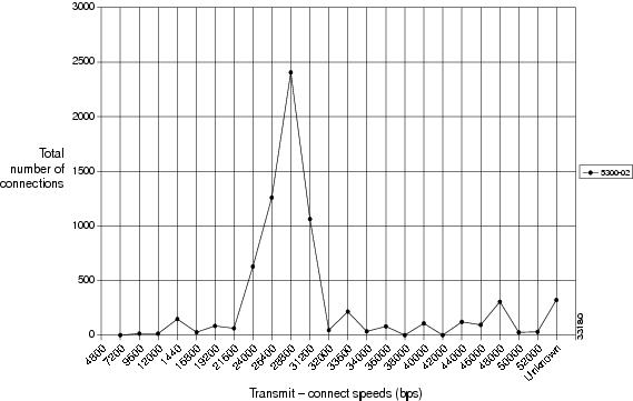
Modem connect speeds can be graphed using SNMP MIBs. The graph shown in Figure 3-13 was created with Cisco Access Manager (CAM). The graph describes the modem connect-speed performance activity of one NAS for one month. The following connect speeds are transmitted by the NAS and received by the client modem. Most of the calls performed between 28000 and 31200 bps. This NAS is one member of an access stack.
For discussions on enabling management protocols such as NTP, SNMP, and Syslog, refer to "Administration."
Figure 3-13 Graphed Modem-Connect Speeds for One Month