Feedback
Table Of Contents
Commissioning the Cisco AS5800 Hardware
Understanding the Basic Hardware Architecture
Cisco 7206 Router Shelf and Cisco 5814 Dial Shelf
Analyzing the System Boot Dialog
Matching the Cisco IOS Software Images
Feature-Card Troubleshooting Tips
Checking the Initial Running-Config
Exploring the Cisco IOS File System
Task 2. Configuring Basic Cisco IOS Software
Configuring the Host Name, Enable Secret Password, and Time Stamps
Configuring Local AAA Security
Task 3. Enabling the T3/T1 Controllers
Task 4. Configuring the Serial Interfaces
Task 5. Configuring Modems and Lines
Task 6. Enabling IP Basic Setup
Task 7. Testing Asynchronous EXEC Shell Connections
Task 8. Confirming the Final Running Configuration
Commissioning
Whether you are a corporate end user or a competitive Internet service provider (ISP), you have purchased a Cisco AS5800 network access server (NAS) to provide dialup services that facilitate accessibility for remote or roaming personnel, or Internet admission to consumers for e-mail, e-commerce, and web browsing.
This chapter details Cisco AS5800 commissioning, or the formal functional setup of the equipment, through systematic software configurations, to initially prepare the system for data/voice call processing.
In our discussion, local-based authentication is used. After the Cisco AS5800 hardware is commissioned, PPP is configured and tested as described in"Configuring PPP and Authentication" section on page 3-25.
Note
A AAA RADIUS server is recommended. AAA Radius server discussions are available in the "Configuring RADIUS" section on page 4-14.
Commissioning the Cisco AS5800 Hardware
This section describes configuring the Cisco AS5800 hardware to support terminal EXEC shell services and log in prompts for client modems, and includes the following:
•
•
•
•
•
•
•
•
•
Note
Understanding the Basic Hardware Architecture
To build an access network using the Cisco AS5800, it is necessary to understand:
•
•
•
Cisco 7206 Router Shelf and Cisco 5814 Dial Shelf
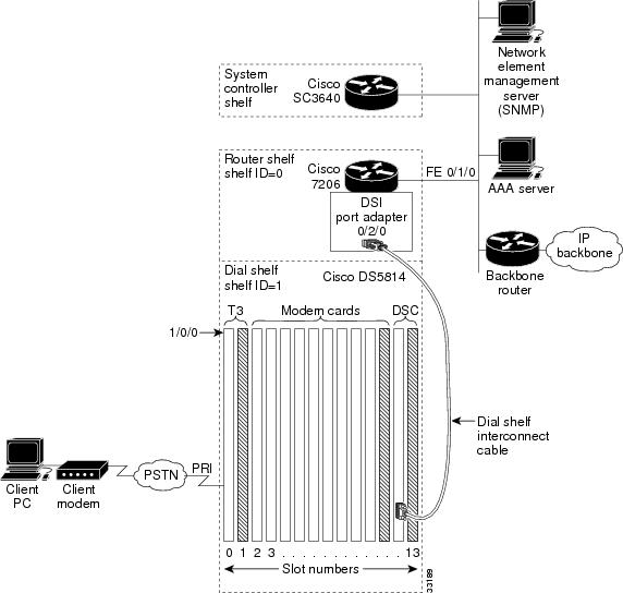
The Cisco AS5800 access server contains:
•
•
Figure 2-1 shows the Cisco AS5800 system architecture.
Figure 2-1 Cisco AS5800 System Architecture
Note
•
–
–
The Cisco 7206 communicates with the Cisco 5814 dial shelf through an external dial-shelf interconnect cable. The cable connects from the DSI port adapter to the dial-shelf controller (DSC) card.
The Dial Shelf Interconnect Protocol (DSIP) enables communication between the Cisco 7206 and the Cisco 5814.
–
–
•
–
The DSC card contains its own Cisco IOS software image. For maintenance purposes only, the card can be accessed through its console port and Ethernet interface. No IP packets originating from any trunk or modem cards go out this Ethernet interface.
–
–
–
•
–
–
Call-Processing Components
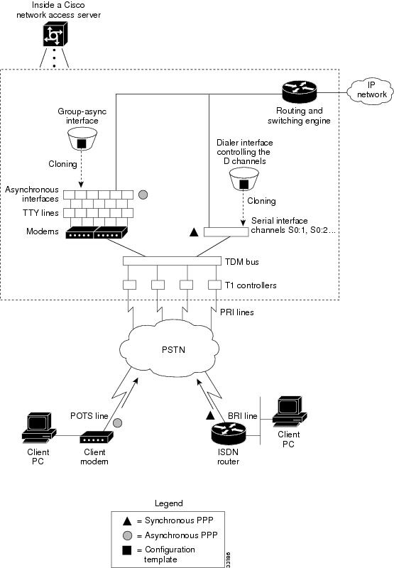
As shown in Figure 2-2, the following components process a call:
•
•
•
•
•
•
Figure 2-2 Cisco AS5800 Call-Processing Components
One asynchronous PPP call requires:
•
•
•
•
•
One synchronous PPP call requires:
•
•
Tips
Task 1. Verifying Basic Setup
Verify that basic system components are functioning:
•
•
•
•
Analyzing the System Boot Dialog
To view the boot sequence through a terminal session, you must have a console connection to the access server before it powers up.
Caution
The following boot sequence occurs. Event numbers and comments are inserted in the example to describe the boot sequence.
System Bootstrap, Version x.xCopyright (c) 20xx by cisco Systems, Inc.C7200 processor with 131072 Kbytes of main memorySelf decompressing the image : ########################################################################################## ################################################# [OK]%PA-2-UNDEFPA: Undefined Port Adaptor type 106 in bay 2%SYS-4-CONFIG_NEWER: Configurations from version 12.x may not be correctly understood.%OIR-3-SEATED: Insert/removal failed (slot 2), check card seating%OIR-3-SEATED: Insert/removal failed (slot 2), check card seatingCCCCCCCCCCCCCCCCCCCCCCCCCCCCCCCCCCCCCCCCCCCCCCCCCCCCCCCCCCCCCCCCCCCCCCCCCCCCCCCCCCC CCCCCCCCCCCCCCCCCCCCCCCCCCCCCCCCCCCCCCCCCCCCCCCCCCCCCCCCCCCCCCCCCCCCCCCCCCCCCCCCCCCCCCCCCC CCCCCCCCCCCCCCCCCCCCCCCCCCCCCCCCCCCCRead 7314384 bytes from file slot0:c5800-p4-mz.120-4.XL1.binSelf decompressing the image : ########################################################################################## ########################################################################################## ########################################################################################## ########################################################################################## ####################################################### [OK]•
Sometimes boot images do not support hardware cards. Sample error messages look like this:
%PA-2-UNDEFPA: Undefined Port Adapter%OIR-3-SEATED: Insert/removal failedIgnore these messages and do not ignore error messages that appear after the Cisco IOS software image decompresses.
Restricted Rights LegendUse, duplication, or disclosure by the Government issubject to restrictions as set forth in subparagraph(c) of the Commercial Computer Software - RestrictedRights clause at FAR sec. 52.227-19 and subparagraph(c) (1) (ii) of the Rights in Technical Data and ComputerSoftware clause at DFARS sec. 252.227-7013.cisco Systems, Inc.170 West Tasman DriveSan Jose, California 95134-1706Cisco Internetwork Operating System Software IOS (tm) 5800 Software (C5800-P4-M), Version 12.xTAC:Home:SW:IOS:Specials for infoCopyright (c) 1986-1999 by cisco Systems, Inc.Compiled Thu 12-Aug-99 13:16 by ayehImage text-base: 0x60008900, data-base: 0x611A6000cisco 7206 (NPE400) processor with 114688K/16384K bytes of memory.R5000 CPU at 200Mhz, Implementation 35, Rev 2.1, 512KB L2 Cache6 slot midplane, Version xLast reset from power-onX.25 software, Version 3.0.0.Bridging software.SuperLAT software (copyright 1990 by Meridian Technology Corp).1 FastEthernet/IEEE 802.3 interface(s)1296 terminal line(s)1 Channelized T3 port(s)125K bytes of non-volatile configuration memory.4096K bytes of packet SRAM memory.20480K bytes of Flash PCMCIA card at slot 0 (Sector size 128K).4096K bytes of Flash internal SIMM (Sector size 256K).•
–
–
–
The following system message and prompt appears.
--- System Configuration Dialog ---Would you like to enter the initial configuration dialog? [yes/no]: no•
00:00:52: %DSIPPF-5-DS_HELLO: DSIP Hello from shelf 1 slot 12 Succeeded00:00:53: %DSC_REDUNDANCY-3-BICLINK: Switching to DSC 1200:00:56: %DSC_REDUNDANCY-3-BICLINK: Link to active DSC up00:02:05: %DSIPPF-5-DS_HELLO: DSIP Hello from shelf 1 slot 0 Succeeded00:02:06: %DSIPPF-5-DS_HELLO: DSIP Hello from shelf 1 slot 2 Succeeded00:02:06: %DSIPPF-5-DS_HELLO: DSIP Hello from shelf 1 slot 3 Succeeded00:02:06: %DSIPPF-5-DS_HELLO: DSIP Hello from shelf 1 slot 4 Succeeded00:02:06: %DSIPPF-5-DS_HELLO: DSIP Hello from shelf 1 slot 5 Succeeded00:02:06: %DSIPPF-5-DS_HELLO: DSIP Hello from shelf 1 slot 6 Succeeded00:02:06: %DSIPPF-5-DS_HELLO: DSIP Hello from shelf 1 slot 7 Succeeded00:02:06: %DSIPPF-5-DS_HELLO: DSIP Hello from shelf 1 slot 8 Succeeded00:02:06: %DSIPPF-5-DS_HELLO: DSIP Hello from shelf 1 slot 9 Succeeded00:02:06: %DSIPPF-5-DS_HELLO: DSIP Hello from shelf 1 slot 10 SucceededPress RETURN to get started!5800>•
Depending on the number of cards in the dial shelf, there is a delay of 60 to 120 seconds before the "DSIP Hello" messages are displayed on your terminal session.
After powering up the Cisco AS5800, enter the show environment command. Verify that there are no critical grounding, heating, or power problems. The following shows an operating environment.
5800-NAS> show environmentAll measured values are normal5800-NAS> show environment allPower Supplies:Power supply 1 is empty.Power supply 2 is Zytek AC Power Supply. Unit is on.Temperature readings:chassis inlet measured at 25C/77Fchassis outlet 1 measured at 27C/80Fchassis outlet 2 measured at 33C/91Fchassis outlet 3 measured at 41C/105FVoltage readings:+3.45 V measured at +3.49 V+5.15 V measured at +5.21 V+12.15 measured at +12.34 V-11.95 measured at -11.81 VEnvm stats saved 1 time(s) since reload5800-NAS>Matching the Cisco IOS Software Images
The dial shelf and router shelf run separate Cisco IOS software images:
•
•
On the router shelf, check the Cisco IOS software image, uptime, and restart reason:
5800# show versionCisco Internetwork Operating System Software IOS (tm) 5800 Software (C5800-P4-M), Version 12.xTAC:Home:SW:IOS:Specials for infoCopyright (c) 1986-1999 by cisco Systems, Inc.Compiled Thu 12-Aug-99 13:16 by ayehImage text-base: 0x60008900, data-base: 0x611A6000ROM: System Bootstrap, Version xCA,BOOTFLASH: 7200 Software (C7200-BOOT-M), Version xRouter uptime is 2 minutesSystem returned to ROM by reloadSystem image file is "slot0:c5800-p4-mz.120-4.XL1.bin"cisco 7206 (NPE400) processor with 114688K/16384K bytes of memory.R5000 CPU at 200Mhz, Implementation 35, Rev 2.1, 512KB L2 Cache6 slot midplane, Version xLast reset from power-onX.25 software, Version 3.0.0.Bridging software.SuperLAT software (copyright 1990 by Meridian Technology Corp).1 FastEthernet/IEEE 802.3 interface(s)1296 terminal line(s)1 Channelized T3 port(s)125K bytes of non-volatile configuration memory.4096K bytes of packet SRAM memory.20480K bytes of Flash PCMCIA card at slot 0 (Sector size 128K).4096K bytes of Flash internal SIMM (Sector size 256K).Configuration register is 0x2102Table 2-1 describes the significant output fields in the previous display:
On the dial shelf, check the Cisco IOS software image, uptime, and restart reason. If you do not have a physical console connection to the dial shelf, enter the execute-on slot [12 | 13] show version command. The DSC can be in slot 12 or 13.
5800# execute-on slot 12 show versionDA-Slot12>Cisco Internetwork Operating System Software IOS (tm) 5800 Software (C5800-DSC-M), Version 12.xTAC:Home:SW:IOS:Specials for infoCopyright (c) 1986-1999 by cisco Systems, Inc.Compiled Thu 12-Aug-99 18:48 by ayehImage text-base: 0x600088F0, data-base: 0x60520000ROM: System Bootstrap, Version xAAROM: 5800 Software (C5800-DSC-M), Version xAA2DA-Slot12 uptime is 20 hours, 38 minutesSystem returned to ROM by reloadSystem image file is "slot0:dsc-c5800-mz.120-4.XL1.bin"cisco c5800 (R4K) processor with 24576K/8192K bytes of memory.R4700 CPU at 150Mhz, Implementation 33, Rev 1.0, 512KB L2 CacheLast reset from power-on1 Ethernet/IEEE 802.3 interface(s)2 Dial Shelf Interconnect(DSI) FE interface(s)123K bytes of non-volatile configuration memory.8192K bytes of Flash PCMCIA card at slot 0 (Sector size 128K).4096K bytes of Flash internal SIMM (Sector size 256K).Configuration register is 0x2102Inspecting the Dial Shelf
Verify that feature cards are up (T3, T1, E3, E1, modem, or voice):
5800# show dial-shelfSlot Board CPU DRAM I/O Memory State ElapsedType Util Total (free) Total (free) Time0 CT3 0%/0% 21598976( 81%) 8388608( 41%) Up 00:01:352 Modem(DMM) 20%/20% 46764800( 86%) 16777216( 74%) Up 00:01:353 Modem(DMM) 0%/0% 46764800( 86%) 16777216( 74%) Up 00:01:354 Modem(DMM) 20%/20% 46764800( 86%) 16777216( 74%) Up 00:01:355 Modem(DMM) 20%/20% 46764800( 86%) 16777216( 74%) Up 00:01:356 Modem(DMM) 40%/40% 46764800( 86%) 16777216( 74%) Up 00:01:357 Modem(DMM) 40%/40% 46764800( 86%) 16777216( 74%) Up 00:01:358 Modem(DMM) 35%/35% 46764800( 86%) 16777216( 74%) Up 00:01:359 Modem(DMM) 0%/0% 46764800( 86%) 16777216( 74%) Up 00:01:3510 Modem(DMM) 20%/20% 46764800( 86%) 16777216( 74%) Up 00:01:3412 DSC 0%/0% 19097792( 79%) 8388608( 66%) Up 00:02:49Dial shelf set for auto boot5800#•
•
•
•
•
•
DSC Troubleshooting Tips
If the DSC card does not come up, perform the following troubleshooting steps. If the DSC card never comes up, the feature cards in the dial shelf cannot communicate with the router shelf.
Step 1
Step 2
Step 3
Step 4
5800> show dsiDSI-Fastethernet0/2/0 is up, line protocol is upHardware is DEC21140A, address is 0030.f2f5.1438 (bia 0030.f2f5.1438)MTU 0 bytes, BW 100000 Kbit, DLY 100 usec,reliability 255/255, txload 1/255, rxload 1/255Encapsulation ARPA, loopback not setKeepalive set (10 sec)Full-duplex, 100Mb/s, 100BaseTX/FXARP type: ARPA, ARP Timeout 04:00:00Last input 00:00:00, output 00:00:00, output hang neverLast clearing of "show interface" counters neverQueueing strategy: fifoOutput queue 0/40, 0 drops; input queue 0/75, 0 drops5 minute input rate 0 bits/sec, 0 packets/sec5 minute output rate 0 bits/sec, 0 packets/sec
Note
5800#00:04:29: %DSIPPF-5-DS_KEEPALIVE_LOSS: DSIP Keepalive Loss from shelf 1 slot 1200:05:12: %DSIPPF-5-DS_HELLO: DSIP Hello from shelf 1 slot 12 Succeeded00:05:18: %DIAL12-3-MSG:00:00:03: %LINK-3-UPDOWN: Interface DSI-Tx-FastEthernet0, changed state to up00:00:03: %LINK-3-UPDOWN: Interface DSI-Rx-FastEthernet1, changed state to up00:00:03: %LINK-3-UPDOWN: Interface Ethernet0, changed state to up5800#
Note
The following messages appear on the console-terminal session after the DSC card is physically removed from slot 12 and re-inserted. Approximately 120 seconds elapse before all these messages appear.
5800>04:41:42: %DSC_REDUNDANCY-3-BICLINK: Link to active DSC down04:42:13: %ISDN-6-LAYER2DOWN: Layer 2 for Interface Se1/0/0:4:23, TEI 0 changed to down04:42:14: %DSC_REDUNDANCY-3-BICLINK: Link to active DSC up04:42:36: %DSIPPF-5-DS_KEEPALIVE_LOSS: DSIP Keepalive Loss from shelf 1 slot 204:42:36: %DSIPPF-5-DS_KEEPALIVE_LOSS: DSIP Keepalive Loss from shelf 1 slot 304:42:46: %DSIPPF-5-DS_KEEPALIVE_LOSS: DSIP Keepalive Loss from shelf 1 slot 004:42:46: %DSIPPF-5-DS_KEEPALIVE_LOSS: DSIP Keepalive Loss from shelf 1 slot 1204:42:53: %DSIPPF-5-DS_HELLO: DSIP Hello from shelf 1 slot 12 Succeeded04:44:59: %DSIPPF-5-DS_HELLO: DSIP Hello from shelf 1 slot 0 Succeeded04:45:02: %DSIPPF-5-DS_HELLO: DSIP Hello from shelf 1 slot 2 Succeeded04:45:03: %DSIPPF-5-DS_HELLO: DSIP Hello from shelf 1 slot 3 Succeeded5800>The following boot sequence occurs in the previous example:
a.
b.
c.
d.
Step 5
Step 6
5800# dsip console slave 12Trying Dial shelf slot 12 ...Entering CONSOLE for slot 12Type "^C^C^C" to end this sessionDA-Slot12>DA-Slot12#DA-Slot12#DA-Slot12#Terminate NIP IO session? [confirm][Connection to Dial shelf slot 12 closed by local host]5800#
Caution
Feature-Card Troubleshooting Tips
If the show dial-shelf command reports that feature cards are booting for extended periods of time, start debugging from the router shelf by using the following commands:
debug dsip transportdebug dsip traceshow dsi•
•
•
Using DSIP
The router shelf communicates with the dial shelf using:
•
•
For the DSIP command reference and other system management functions, refer to Dial and System Management Commands for the Cisco AS5800, available online at
http://www.cisco.com/univercd/cc/td/doc/product/software/ios113ed/113aa/113aa_2/58cfeats/c5800uas.htmTo understand how DSIP functions, enter commands from the following bullet list:
•
5800-NAS# show dsiDSI-Fastethernet0/2/0 is up, line protocol is upHardware is DEC21140A, address is 00d0.d342.4c38 (bia 00d0.d342.4c38)MTU 0 bytes, BW 100000 Kbit, DLY 100 usec,reliability 255/255, txload 1/255, rxload 1/255Encapsulation ARPA, loopback not setKeepalive set (10 sec)Full-duplex, 100Mb/s, 100BaseTX/FXARP type: ARPA, ARP Timeout 04:00:00Last input 00:00:00, output 00:00:00, output hang neverLast clearing of "show interface" counters neverQueueing strategy: fifoOutput queue 0/40, 0 drops; input queue 0/75, 0 drops5 minute input rate 0 bits/sec, 0 packets/sec•
5800# show dsip transportDSIP transport statistics:IPC : input msgs=4309, bytes=509139; output msgs=4308, bytes=291468total consumed ipc msgs=2133; total freed ipc msgs = 2133transmit contexts in use = 13, free = 243, zombie = 0, invalid = 0ipc getmsg failures = 0, ipc timeouts=0core getbuffer failures=0, api getbuffer failures=0dsip test msgs rcvd = 0, sent = 0CNTL : input msgs=20927, bytes=738902; output msgs=20350, bytes=29816080getbuffer failures=0DATA : input msgs=1076, bytes=38736; output msgs=0, bytes=0DSIP Private Buffer Pool Hits = 0DSIP registered addresses:Shelf0 : Master: 00d0.d342.4c38, Status=localShelf1 : Slot0 : 0090.bf52.4e00, Status=remoteShelf1 : Slot2 : 0090.bf52.4e10, Status=remoteShelf1 : Slot3 : 0090.bf52.4e18, Status=remoteShelf1 : Slot4 : 0090.bf52.4e20, Status=remoteShelf1 : Slot5 : 0090.bf52.4e28, Status=remoteShelf1 : Slot6 : 0090.bf52.4e30, Status=remoteShelf1 : Slot7 : 0090.bf52.4e38, Status=remoteShelf1 : Slot8 : 0090.bf52.4e40, Status=remoteShelf1 : Slot9 : 0090.bf52.4e48, Status=remoteShelf1 : Slot10: 0090.bf52.4e50, Status=remoteShelf1 : Slot12: 0090.bf52.4e60, Status=remote5800#•
5800# show dsip versionDSIP version information:------------------------Local DSIP major version = 5, minor version = 2All feature cards are running DSIP versions compatible with router shelfLocal clients registered versions:------------------------------------Client Name Major Version Minor VersionConsole 5 2Clock 2 1Modem 0 0Logger No version No versionTDM No version No versionTrunk No version No versionAsync data No version No versionVOICE 0 0Dial shelf 1 1Environment No version No versionFILESYS No version No versionDSC Red. UI 0 1Split DS No version No versionDSIP Test No version No versionMismatched remote client versions:-----------------------------------5800#
Note
Checking the Initial Running-Config
The Cisco IOS software creates an initial running configuration. To familiarize yourself with default settings, inspect the software configuration as follows:
Step 1
5800# show running-configBuilding configuration...Current configuration:!version 12.xservice timestamps debug uptimeservice timestamps log uptimeno service password-encryption!hostname Router!!shelf-id 0 router-shelfshelf-id 1 dial-shelf!!resource-pool disable!modem-pool Defaultpool-range 1/2/0-1/10/143!!spe 1/2/0 1/10/11firmware ios-bundled defaultmodem recovery action noneip subnet-zero!isdn voice-call-failure 0!!controller T3 1/0/0cablelength 224!!process-max-time 200!interface FastEthernet0/1/0no ip addressno ip directed-broadcastshutdown!interface Group-Async0no ip addressno ip directed-broadcastgroup-range 1/2/00 1/10/143!ip classlessno ip http server!!line con 0transport input noneline aux 0line vty 0 4line 1/2/00 1/10/143modem InOutno modem log rs232!endStep 2
5800# execute-on slot 12 show running-configDA-Slot12#Building configuration...Current configuration:!version 12.xservice configno service padservice timestamps debug uptimeservice timestamps log uptimeno service password-encryption!hostname DA-Slot12!!ip subnet-zero!!process-max-time 200!interface Ethernet0no ip addressno ip directed-broadcastshutdown!no ip http serverip classless!!line con 0transport input noneline vty 0 4!end
Exploring the Cisco IOS File System
Familiarize yourself with the file system and memory storage areas. The Cisco IOS file system provides a consolidated interface to:
•
•
•
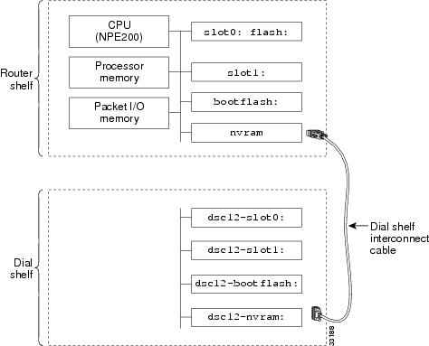
Figure 2-3 shows the memory locations inside the Cisco AS5800.
Figure 2-3 Cisco AS5800 Memory Locations
Table 2-2 describes the memory locations shown in Figure 2-3.
To verify the file system, enter commands from the following bullet list:
•
5800# show file systemsFile Systems:Size(b) Free(b) Type Flags Prefixes- - flash rw disk0:- - flash rw disk1:- - opaque rw null:- - opaque rw system:- - network rw tftp:129016 128277 nvram rw nvram:* 20578304 13263792 flash rw slot0: flash:- - flash rw slot1:3407872 1286636 flash rw bootflash:- - opaque wo lex:- - network rw rcp:- - network rw pram:- - network rw ftp:7995392 5825440 flash rw dsc12-slot0:- - flash rw dsc12-slot1:3407872 1575412 flash rw dsc12-bootflash:126968 126968 nvram rw dsc12-nvram:5800#•
5800# dir system:Directory of system:/2 dr-x 0 <no date> memory1 -rw- 787 <no date> running-configNo space information available5800#
Tips
•
5800# pwdslot0:5800# dirDirectory of slot0:/1 -rw- 7314384 Sep 13 1999 20:03:41 c5800-p4-mz.120-4.XL1.bin20578304 bytes total (13263792 bytes free)5800#5800# dir dsc12-slot0:Directory of dsc12-slot0:/1 -rw- 2169824 Sep 13 1999 20:28:53 dsc-c5800-mz.120-4.XL1.bin7995392 bytes total (5825440 bytes free)5800#•
5800# dir bootflash:Directory of bootflash:/1 -rw- 2121108 Jan 01 2000 00:00:48 c7200-boot-mz.111-24.CC3407872 bytes total (1286636 bytes free)Router5800# dir dsc12-bootflash:Directory of dsc12-bootflash:/1 -rw- 2169824 Nov 18 1999 22:18:30 dsc-c5800-mz.120-4.XL1.bin3407872 bytes total (1237920 bytes free)
Tips
The squeeze command is required to remove deleted files:
5800-NAS# pwddsc12-bootflash:/5800-NAS# delete dsc-c5800-mz.113-9.AA2Delete filename [dsc-c5800-mz.113-9.AA2]?Delete dsc12-bootflash:dsc-c5800-mz.113-9.AA2? [confirm]5800-NAS# squeeze dsc12-bootflash:All deleted files will be removed. Continue? [confirm]Squeeze operation may take a while. Continue? [confirm]DA-Slot12#All deleted files will be removed. Continue? [confirm]Squeeze operation may take a while. Continue? [confirm]Squeeze of bootflash completeSqueeze of dsc12-bootflash complete5800-NAS#•
–
–
–
5800# dir nvram:Directory of nvram:/1 -rw- 739 <no date> startup-config2 ---- 24 <no date> private-config3 -rw- 739 <no date> underlying-config129016 bytes total (128277 bytes free)5800#5800# dir dsc12-nvram:Directory of dsc12-nvram:/1 -rw- 0 <no date> startup-config2 ---- 0 <no date> private-config3 -rw- 0 <no date> underlying-config126968 bytes total (126968 bytes free)5800#Investigating Memory Usage
Use the show memory summary command to:
•
•
–
–
To inspect and calculate memory usage complete the following steps:
Step 1
5800-NAS# show memory summmaryHead Total(b) Used(b) Free(b) Lowest(b) Largest(b)Processor 6164D4E0 94055200 42346480 51708720 50435436 51592056I/O 7000000 16777216 6433400 10343816 10343816 10343772PCI 4B000000 4194304 618584 3575720 3575720 3575676
Caution
Table 2-3 describes the significant fields in the previous display:
Step 2
•
•
•
Total memory (89.7 MB) = Used memory (40.4 MB) + free memory (49.3 MB)
Step 3
Total Processor = Total RAM - Cisco IOS software (use the show version command to get the MB assigned for all of Cisco IOS software + Processor)
cisco 7206 (NPE400) processor with 114688K/16384K bytes of memory.114688 KB / (1024 KB / MB) = 112.0 MB
16384 KB = 16 MB
112 MB + 16 MB = 128 MB (what you purchased).
Note
Verifying CPU Utilization
High utilization causes network performance problems. Knowing when the router is running at over 50% utilization is critical because the router might start dropping packets if an unexpected traffic burst comes through or if OSPF gets recalculated. Fast switching reduces CPU utilization.
5800# show processes cpuCPU utilization for five seconds: 20%/6%; one minute: 31%; five minutes: 19%PID Runtime(ms) Invoked uSecs 5Sec 1Min 5Min TTY Process1 144208 1526300 94 0.00% 0.00% 0.00% 0 Load Meter2 118732 19749060 6 0.24% 0.12% 0.08% 0 OSPF Hello3 42752544 2699659 15836 3.75% 0.87% 0.62% 0 Check heaps4 7260 30062 241 0.00% 0.00% 0.00% 0 Pool Manager5 0 2 0 0.00% 0.00% 0.00% 0 Timers6 1472 494101 2 0.00% 0.00% 0.00% 0 Serial Background7 49424 7631216 6 0.00% 0.00% 0.00% 0 EnvMon8 0 1 0 0.00% 0.00% 0.00% 0 OIR Handler9 13368616 3217631 4154 0.32% 0.57% 0.42% 0 ARP Input10 18932 533419 35 0.00% 0.00% 0.00% 0 DDR Timers11 116 4 29000 0.00% 0.00% 0.00% 0 Entity MIB APILook at the top line of the output. If you see utilization at the top of the display over 50%, inspect the columns 5Sec, 1Min, and 5Min. Find the process that uses the most CPU power. For an idle chassis, numbers larger than two percent indicate a problem.
Table 2-4 describes the significant output fields in the previous example:
Whenever memory cannot be allocated to a process request (a memory leak), a console error message appears:
Sep 14 11:30:33.339 EDT: %SYS-2-MALLOCFAIL: Memory allocation of 19960bytes failed from 0x603D530C, pool Processor, alignment 0-Process= "Exec", ipl= 0, pid= 48-Traceback= 603D8610 603DAA70 603D5314 603D5AF0 60373054 60371474 603C33DC603C3538 603C4378 60371934 603586B8 60358A10 6037C12C 6037C1E4 60372E9C6037EDECTo identify the problem, inspect the first few output lines of the show memory summary command and show processor memory command.
Task 2. Configuring Basic Cisco IOS Software
Apply a basic-running configuration to the NAS:
•
•
Tips
Configuring the Host Name, Enable Secret Password, and Time Stamps
Assign a host name to the NAS, specify an enable secret password, and turn on time stamps:
•
•
•
•
Step 1
hostname 5800-NASenable secret yourpasswordservice password-encryptionservice timestamps debug datetime msecservice timestamps log datetime msec
Note
Step 2
5800-NAS# disable5800-NAS> enablePassword:5800-NAS# show privilegeCurrent privilege level is 155800-NAS#
Configuring Local AAA Security
Configure AAA to perform login authentication by using the local username database. The login keyword authenticates EXEC shell users. Additionally, configure PPP authentication to use the local database if the session was not already authenticated by login.
AAA is the Cisco IOS software security model used on all Cisco devices. AAA provides the primary framework through which you set up access control on the NAS.
In this basic discussion, the same authentication method is used on all interfaces. AAA is set up to use the local database configured on the NAS. This local database is created with the username configuration commands.
Step 1
!username admin password adminpasshereusername dude password passhere!
Caution
Step 2
!aaa new-modelaaa authentication login default localaaa authentication ppp default if-needed local!Table 2-5 describes the configuration:
Step 3
5800-NAS# loginUser Access VerificationUsername:adminPassword:5800-NAS#A successful login means that your local username works on any TTY or VTY line. Do not disconnect your session until you can log in.
Setting Up a Log In Banner
Create a login banner. However, do not tell users what device they are connecting to until after they log in. Providing device sensitive information can tempt unauthorized users to hack into the system.
Step 1
5800-NAS(config)# banner login |Enter TEXT message. End with the character '|'.This is a secured device.Unauthorized use is prohibited by law.|5800-NAS(config)#^Z5800-NAS#Step 2
5800-NAS#5800-NAS# loginThis is a secured device.Unauthorized use is prohibited by law.User Access VerificationUsername: adminPassword:5800-NAS#
Configuring Basic IP
To configure a basic dial access service:
•
•
•
Follow this procedure:
Step 1
!interface Loopback0ip address 172.22.99.1 255.255.255.255!interface Loopback1ip address 172.22.90.1 255.255.255.0!interface FastEthernet0/1/0ip address 172.22.66.23 255.255.255.0!ip route 0.0.0.0 0.0.0.0 172.22.66.1!The loopback interfaces are used for the following reasons:
•
•
Step 2
5800-NAS# ping 172.22.66.1Type escape sequence to abort.Sending 5, 100-byte ICMP Echos to 172.22.66.1, timeout is 2 seconds:.!!!!Success rate is 80 percent (4/5), round-trip min/avg/max = 1/1/1 ms5800-NAS#This step verifies that you have IP connectivity with another device on the subnet. If the ping succeeds to the default gateway, try pinging the DNS server in your backbone. Make sure the backbone is configured to get to the access server; otherwise, the ping will not work. Configure the backbone routers to support the routes to the networks you are using.
Note
Task 3. Enabling the T3/T1 Controllers
Configure the settings for the T3/T1 controllers. They must match the telco's settings on the telephone switch. Mismatched settings cause problems; sometimes these problems are not detected for a long time.
Figure 2-4 displays the logical controller components inside a Cisco AS5800. The figure shows that a T3 trunk card requires T1 and T3 controller configuration settings. In the figure, only the fourth controller is configured. There are a total of 28 T1 controllers to configure.
Figure 2-4 Matching Controller Settings
Step 1
!isdn switch-type primary-ni!There are two ways to define the switch type:
•
•
Note
Step 2
!controller T3 1/0/0framing m23cablelength 0t1 4 controller!Step 3
!controller t1 1/0/0:4framing esfpri-group timeslots 1-24!After the controllers are correctly configured, the following cards and interfaces change state:
00:01:59: %CONTROLLER-5-UPDOWN: Controller T3 1/0/0, changed state to up00:02:01: %CONTROLLER-5-UPDOWN: Controller T1 1/0/0:4, changed state to up00:02:02: %DIAL12-3-MSG:07:08:54: %DSCCLOCK-3-SWITCH3: Clock moving to NORMAL from HOLDOVER, selected clock is on slot 0 port 4 line 000:02:05: %ISDN-6-LAYER2DOWN: Layer 2 for Interface Se1/0/0:4:23, TEI 0 changedto down00:02:21: %ISDN-6-LAYER2UP: Layer 2 for Interface Se1/0/0:4:23, TEI 0 changed to up5800-NAS>Table 2-6 describes some of the T3 and T1-controller concepts that are applied in the previous steps.
Step 4
5800-NAS# show controller t3T3 1/0/0 is up.Applique type is Channelized T3No alarms detected.FEAC code received: No code is being receivedFraming is M23, Line Code is B3ZS, Clock Source is InternalData in current interval (201 seconds elapsed):0 Line Code Violations, 0 P-bit Coding Violation0 C-bit Coding Violation, 0 P-bit Err Secs0 P-bit Severely Err Secs, 0 Severely Err Framing Secs0 Unavailable Secs, 0 Line Errored Secs0 C-bit Errored Secs, 0 C-bit Severely Errored SecsTotal Data (last 1 15 minute intervals):30664 Line Code Violations, 49191 P-bit Coding Violation,47967 C-bit Coding Violation, 0 P-bit Err Secs,0 P-bit Severely Err Secs, 0 Severely Err Framing Secs,2 Unavailable Secs, 0 Line Errored Secs,10 C-bit Errored Secs, 10 C-bit Severely Errored Secs5800-NAS#5800-NAS# show controller T1 1/0/0:4T1 1/0/0:4 is up.Applique type is Channelized T1Cablelength is shortNo alarms detected.Framing is ESF, Line Code is AMI, Clock Source is Line.Data in current interval (240 seconds elapsed):0 Line Code Violations, 0 Path Code Violations0 Slip Secs, 0 Fr Loss Secs, 0 Line Err Secs, 0 Degraded Mins0 Errored Secs, 0 Bursty Err Secs, 0 Severely Err Secs, 0 Unavail SecsData in Interval 1:0 Line Code Violations, 8 Path Code Violations11 Slip Secs, 26 Fr Loss Secs, 0 Line Err Secs, 0 Degraded Mins0 Errored Secs, 0 Bursty Err Secs, 0 Severely Err Secs, 26 Unavail SecsTotal Data (last 1 15 minute intervals):0 Line Code Violations, 8 Path Code Violations,11 Slip Secs, 26 Fr Loss Secs, 0 Line Err Secs, 0 Degraded Mins,0 Errored Secs, 0 Bursty Err Secs, 0 Severely Err Secs, 26 Unavail Secs5800-NAS#After each controller is correctly set up, clear the counters and look for ongoing line violations and errors. To do this, enter the clear counters command followed by the show counters command:
clear counters t1 1/0/0:4show counters t1 1/0/0:4Step 5
Tips
From the reference point of the NAS, Table 2-7 provides a list of T1 alarm conditions and descriptions.
For more information about controllers, see the information on channelized E1 and channelized T1 setup commands in Dial-In Port Setup, available online at
http://www.cisco.com/univercd/cc/td/doc/product/software/ios120/12cgcr/dial_r/drprt1/index.htmStep 6
5800-NAS# show ip interface brief | inc :23Serial1/0/0:4:23 unassigned YES NVRAM up up5800-NAS#Step 7
Task 4. Configuring the Serial Interfaces
Configure the serial D channels to route incoming voice calls from the PSTN to the integrated modems. The behavior of the B channels is controlled by the D channels configuration instructions. The D channel is the signaling channel.
Table 2-8 describes the relationship between T1 controllers and serial interfaces.
•
•
•
Step 1
!interface Serial1/0/0:4:23isdn incoming-voice modem!Step 2
•
5800-NAS# show isdn statusGlobal ISDN Switchtype = primary-niISDN Serial1/0/0:4:23 interfacedsl 0, interface ISDN Switchtype = primary-niLayer 1 Status:ACTIVELayer 2 Status:TEI = 0, Ces = 1, SAPI = 0, State = MULTIPLE_FRAME_ESTABLISHEDLayer 3 Status:0 Active Layer 3 Call(s)Activated dsl 0 CCBs = 0The Free Channel Mask: 0x807FFFFFTotal Allocated ISDN CCBs = 0•
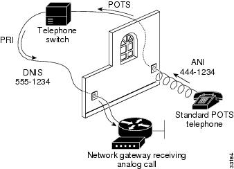
5800-NAS# show isdn servicePRI Channel Statistics:ISDN Se1/0/0:4:23, Channel [1-24]Configured Isdn Interface (dsl) 0Channel State (0=Idle 1=Propose 2=Busy 3=Reserved 4=Restart 5=Maint_Pend)0 0 0 0 0 0 0 0 0 0 0 0 0 0 0 0 0 0 0 0 0 0 0 3Service State (0=Inservice 1=Maint 2=Outofservice)0 0 0 0 0 0 0 0 0 0 0 0 0 0 0 0 0 0 0 0 0 0 0 05800-NAS#Step 3
Figure 2-5 Sending a POTs Telephone Call to a NAS
Note
•
•
Task 5. Configuring Modems and Lines
Modems and lines are configured after:
•
•
Each modem is mapped to a dedicated asynchronous line inside the NAS. After the modem inout command is applied to the lines, the NAS is ready to accept modem calls.
AAA security is applied to the lines by the aaa new-model command and aaa authentication login default local command. AAA performs login authentication by using the local username database. The login keyword authenticates EXEC shell users.
Note
Step 1
!line 1/2/00 1/10/143modem InOut!
Note
Step 2
5800-NAS# show modemCodes:* - Modem has an active callT - Back-to-Back test in progressR - Modem is being Resetp - Download request is pending and modem cannot be used for taking callsD - Download in progressB - Modem is marked bad and cannot be used for taking callsb - Modem is either busied out or shut-downd - DSP software download is required for achieving K56flex connections! - Upgrade request is pendingAvg Hold Inc calls Out calls Busied Failed No SuccMdm Time Succ Fail Succ Fail Out Dial Answer Pct1/2/00 00:00:00 0 0 0 0 0 0 0 0%1/2/01 00:00:00 0 0 0 0 0 0 0 0%1/2/02 00:00:00 0 0 0 0 0 0 0 0%1/2/03 00:00:00 0 0 0 0 0 0 0 0%1/2/04 00:00:00 0 0 0 0 0 0 0 0%Step 3
TTY line numbers map to specific slots. Each slot is hard coded with 144 TTY lines. In the example, the first modem card is in slot—that is, slot 0 and slot 1 do not contain modem cards.
5800-NAS# show modem 1/2/00Mdm Typ Status Tx/Rx G Duration RTS CTS DCD DTR--- --- ------ ----- - -------- --- --- --- ---1/2/00 (n/a) Idle 0/0 1 00:00:00 RTS CTS noDCD DTRModem 1/2/00, Cisco MICA modem (Managed), Async1/2/00, TTY432Firmware Rev: 2.6.2.0Modem config: Incoming and OutgoingProtocol: (n/a), Compression: (n/a)Management config: Status pollingRX signals: 0 dBmLast clearing of "show modem" counters never0 incoming completes, 0 incoming failures0 outgoing completes, 0 outgoing failures0 failed dial attempts, 0 ring no answers, 0 busied outs0 no dial tones, 0 dial timeouts, 0 watchdog timeouts0 no carriers, 0 link failures, 0 resets, 0 recover oob0 recover modem, 0 current fail count0 protocol timeouts, 0 protocol errors, 0 lost eventsTask 6. Enabling IP Basic Setup
Tune IP routing behavior and domain-name services for EXEC shell users by completing the following steps:
Step 1
ip subnet-zerono ip source-routeip classlessTable 2-9 describes the previous commands:
Step 2
ip domain-lookupip host aurora 172.22.100.9ip domain-name the.docip name-server 172.22.11.10ip name-server 172.22.12.10Table 2-10 describes the previous commands:
Task 7. Testing Asynchronous EXEC Shell Connections
This task verifies that the following components are working:
•
•
•
The Cisco IOS software provides a command-line interface (CLI) called the EXEC.
The EXEC:
•
•
–
–
–
–
During this task, some administrators try to make complex services function such as PPP-based Web browsing. Do not jump ahead. Many other elements still need to be configured (for example, PPP and IPCP). The asynchronous-shell test ensures that the EXECs log in prompt can be accessed by a client modem. Taking a layered approach to building a network isolates problems and saves time.
Note
Step 1
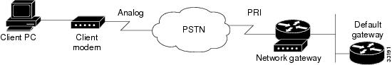
Figure 2-6 Test Environment
Step 2
atOKStep 3
atdt5551234CONNECT 28800 V42bis
Tips
Step 4
This is a secured device.Unauthorized use is prohibited by law.User Access VerificationUsername: theuserPassword:5800-NAS>Step 5
5800-NAS# show callerActive IdleLine User Service Time Timecon 0 admin TTY 00:13:43 00:00:00tty 436 theuser TTY 00:00:20 00:00:085800-NAS# show caller user theuserUser: dude, line tty 436, service TTYActive time 00:00:34, Idle time 00:00:09Timeouts: Absolute Idle IdleSession ExecLimits: - - 00:10:00Disconnect in: - - 00:09:50TTY: Line 1/2/04DS0: (slot/unit/channel)=0/4/2Status: Ready, Active, No Exit BannerCapabilities: Hardware Flowcontrol In, Hardware Flowcontrol OutModem Callout, Modem RI is CDModem State: Ready5800-NAS#
Note
Step 6
5800-NAS> telnet 172.22.66.26Trying 172.22.66.26 ... OpenUser Access VerificationUsername: adminPassword:5800-NAS>5800-NAS> telnet auroraTranslating "aurora"...domain server (172.22.11.10) [OK]Trying aurora.cisco.com (172.22.2.2)... OpenSunOS 5.6login: theuserPassword:Last login: Wed Oct 6 08:57:46 from dhcp-aus-163-236Sun Microsystems Inc. SunOS 5.6 Generic August 1997aurora%
Task 8. Confirming the Final Running Configuration
After you complete the tasks in this section, the final running configuration looks like this:
5800-NAS# show running-configBuilding configuration...Current configuration:!version 12.xservice timestamps debug datetime msecservice timestamps log datetime msecservice password-encryption!hostname 5800-NAS!aaa new-modelaaa authentication login default localaaa authentication ppp default if-needed localenable secret 5 $1$gq.d$nZwr.ElnV/O0nE9U.wZ3D/!username admin password 7 105B1D1A0A12username dude password 7 111C0D061817!!!!shelf-id 0 router-shelfshelf-id 1 dial-shelf!!!resource-pool disable!modem-pool Defaultpool-range 1/2/0-1/10/143!!spe 1/2/0 1/10/11firmware ios-bundled defaultmodem recovery action noneip subnet-zerono ip source-routeip host aurora 172.22.100.9ip domain-name the.docip name-server 172.22.11.10ip name-server 172.22.12.11!isdn switch-type primary-niisdn voice-call-failure 0!!controller T3 1/0/0framing m23cablelength 0t1 4 controller!controller T1 1/0/0:4framing esfpri-group timeslots 1-24!!voice-port 1/0/0:4:D!!process-max-time 200!interface Loopback0ip address 172.22.99.1 255.255.255.255no ip directed-broadcast!interface Loopback1ip address 172.22.90.1 255.255.255.0no ip directed-broadcast!interface FastEthernet0/1/0ip address 172.22.66.23 255.255.255.0no ip directed-broadcast!interface Serial1/0/0:4:23no ip addressno ip directed-broadcastisdn switch-type primary-niisdn incoming-voice modemno cdp enable!interface Group-Async0no ip addressno ip directed-broadcastgroup-range 1/2/00 1/10/143!ip classlessip route 0.0.0.0 0.0.0.0 172.22.66.1no ip http server!!banner login ^CThis is a secured device.Unauthorized use is prohibited by law.^C!line con 0transport input noneline aux 0line vty 0 4line 1/2/00 1/10/143modem InOutno modem log rs232!end