Downloads |
 Feedback Feedback
|
Table Of Contents
Configuring PPP over Ethernet with NAT
Configure the Virtual Private Dialup Network Group Number
Configure the Fast Ethernet WAN Interfaces
Configure the Dialer Interface
Configure Network Address Translation
Configuring PPP over Ethernet with NAT
The Cisco 851 and Cisco 871access routers support Point-to-Point Protocol over Ethernet (PPPoE) clients and network address translation (NAT).
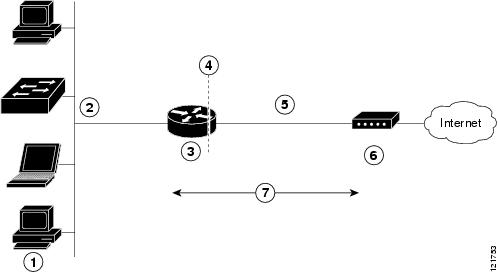
Multiple PCs can be connected to the LAN behind the router. Before the traffic from these PCs is sent to the PPPoE session, it can be encrypted, filtered, and so forth. Figure 3-1 shows a typical deployment scenario with a PPPoE client and NAT configured on the Cisco router.
Figure 3-1 PPP over Ethernet with NAT
PPPoE
The PPPoE Client feature on the router provides PPPoE client support on Ethernet interfaces. A dialer interface must be used for cloning virtual access. Multiple PPPoE client sessions can be configured on an Ethernet interface, but each session must use a separate dialer interface and a separate dialer pool.
A PPPoE session is initiated on the client side by the Cisco 850 or Cisco 870 series router.An established PPPoE client session can be terminated in one of two ways:
•
By entering the clear vpdn tunnel pppoe command. The PPPoE client session terminates, and the PPPoE client immediately tries to reestablish the session. This also occurs if the session has a timeout.
•
NAT
NAT (represented as the dashed line at the edge of the Cisco router) signifies two addressing domains and the inside source address. The source list defines how the packet travels through the network.
Configuration Tasks
Perform the following tasks to configure this network scenario:
•
•
•
•
An example showing the results of these configuration tasks is shown in the "Configuration Example" section.
Configure the Virtual Private Dialup Network Group Number
Configuring a virtual private dialup network (VPDN) enables multiple clients to communicate through the router by way of a single IP address.
Complete the following steps to configure a VPDN, starting from the global configuration mode. See the "Configure Global Parameters" section on page 1-5 for details about entering this mode.
Configure the Fast Ethernet WAN Interfaces
In this scenario, the PPPoE client (your Cisco router) communicates over a 10/100 Mbps-Ethernet interface on both the inside and the outside.
Perform these steps to configure the Fast Ethernet WAN interfaces, starting in global configuration mode:
Configure the Dialer Interface
The dialer interface indicates how to handle traffic from the clients, including, for example, default routing information, the encapsulation protocol, and the dialer pool to use. The dialer interface is also used for cloning virtual access. Multiple PPPoE client sessions can be configured on a Fast Ethernet interface, but each session must use a separate dialer interface and a separate dialer pool.
Complete the following steps to configure a dialer interface for one of the Fast Ethernet LAN interfaces on the router, starting in global configuration mode.
Configure Network Address Translation
Network Address Translation (NAT) translates packets from addresses that match a standard access list, using global addresses allocated by the dialer interface. Packets that enter the router through the inside interface, packets sourced from the router, or both are checked against the access list for possible address translation. You can configure NAT for either static or dynamic address translations.
Perform these steps to configure the outside Fast Ethernet WAN interface with dynamic NAT, beginning in global configuration mode:
Step 1
ip nat pool name start-ip end-ip {netmask netmask | prefix-length prefix-length}
Example:
Router(config)# ip nat pool pool1 192.168.1.0 192.168.2.0 netmask 255.255.252.0Router(config)#Creates pool of global IP addresses for NAT.
Step 2
ip nat inside source {list access-list-number} {interface type number | pool name} [overload]
Example 1:
Router(config)# ip nat inside source list 1
interface dialer 0 overload
or
Example 2:
Router(config)# ip nat inside source list
acl1 pool pool1
Enables dynamic translation of addresses on the inside interface.
The first example shows the addresses permitted by the access list 1 to be translated to one of the addresses specified in the dialer interface 0.
The second example shows the addresses permitted by access list acl1 to be translated to one of the addresses specified in the NAT pool pool1.
For details about this command and additional parameters that can be set, as well as information about enabling static translation, see the Cisco IOS IP Command Reference, Volume 1 of 4: Addressing and Services.
Step 3
interface type number
Example:
Router(config)# interface vlan 1Router(config-if)#Enters configuration mode for the VLAN (on which the Fast Ethernet LAN interfaces [FE0-FE3] reside) to be the inside interface for NAT.
Step 4
ip nat {inside | outside}
Example:
Router(config-if)# ip nat insideRouter(config-if)#Identifies the specified VLAN interface as the NAT inside interface.
For details about this command and additional parameters that can be set, as well as information about enabling static translation, see the Cisco IOS IP Command Reference, Volume 1 of 4: Addressing and Services.
Step 5
no shutdown
Example:
Router(config-if)# no shutdownRouter(config-if)#Enables the configuration changes just made to the Ethernet interface.
Step 6
exit
Example:
Router(config-if)# exitRouter(config)#Exits configuration mode for the Fast Ethernet interface.
Step 7
interface type number
Example:
Router(config)# interface fastethernet 4Router(config-if)#Enters configuration mode for the Fast Ethernet WAN interface (FE4) to be the outside interface for NAT.
Step 8
ip nat {inside | outside}
Example:
Router(config-if)# ip nat outsideRouter(config-if)#Identifies the specified WAN interface as the NAT outside interface.
For details about this command and additional parameters that can be set, as well as information about enabling static translation, see the Cisco IOS IP Command Reference, Volume 1 of 4: Addressing and Services.
Step 9
no shutdown
Example:
Router(config-if)# no shutdownRouter(config-if)#Enables the configuration changes just made to the Ethernet interface.
Step 10
exit
Example:
Router(config-if)# exitRouter(config)#Exits configuration mode for the Fast Ethernet interface.
Step 11
access-list access-list-number {deny | permit} source [source-wildcard]
Example:
Router(config)# access-list 1 permit
192.168.1.0 255.255.255.0
Defines a standard access list indicating which addresses need translation.
Note
Note
For complete information on the NAT commands, see the Cisco IOS Release 12.3 documentation set. For more general information on NAT concepts, see Appendix B, "Concepts."
Configuration Example
The following configuration example shows a portion of the configuration file for the PPPoE scenario described in this chapter.
The VLAN interface has an IP address of 192.168.1.1 with a subnet mask of 255.255.255.0. NAT is configured for inside and outside
Note
vpdn enable
vpdn-group 1
request-dialin
protocol pppoe
!
interface vlan 1
ip address 192.168.1.1 255.255.255.0
no ip directed-broadcast (default)
ip nat inside
interface FastEthernet 4 no ip address no ip directed-broadcast (default) ip nat outside pppoe enable group global pppoe-client dial-pool-number 1 no sh! interface dialer 1 ip address negotiated ip mtu 1492 encapsulation ppp ppp authentication chap dialer pool 1 dialer-group 1 ! dialer-list 1 protocol ip permit ip nat inside source list 1 interface dialer 0 overload ip classless (default) ip route 10.10.25.2 255.255.255.255 dialer 0ip nat pool pool1 192.168.1.0 192.168.2.0 netmask 255.255.252.0 ip nat inside source list acl1 pool pool1!Verifying Your Configuration
Use the show ip nat statistics command in privileged EXEC mode to verify the PPPoE with NAT configuration. You should see verification output similar to the following example:
Router# show ip nat statisticsTotal active translations: 0 (0 static, 0 dynamic; 0 extended)Outside interfaces:FastEthernet4Inside interfaces:Vlan1Hits: 0 Misses: 0CEF Translated packets: 0, CEF Punted packets: 0Expired translations: 0Dynamic mappings:-- Inside Source[Id: 1] access-list 1 interface Dialer0 refcount 0Queued Packets: 0