Feedback Feedback
|
Table Of Contents
Configuring Dial Backup and Remote Management
Dial Backup Feature Activation Methods
Configuring Floating Static Routes
Dial Backup Feature Limitations
Configuring Dial Backup and Remote Management Through the Console or Auxiliary Port
Configuring Dial Backup and Remote Management Through the ISDN S/T Port
Configure the Aggregator and ISDN Peer Router
Configuring Dial Backup and Remote Management
The Cisco 800 series access routers support dial-in (for remote management) and dial-out (for dial backup) capabilities. By allowing you to configure a backup modem line connection, the Cisco 800 series access routers provide protection against WAN downtime. Dial backup is inactive by default, and must be configured to be active.
Dial backup functions can be configured as follows:
•
Through the auxiliary port on any Cisco 870 series router
•
Remote management functions can be configured as follows:
•
•
Note
This chapter contains the following topics:
•
•
•
•
Dial Backup Feature Activation Methods
Three methods are available to activate the dial backup feature:
Backup Interfaces
When the router receives an indication that the primary line is down, a backup interface is brought up. You can configure the backup interface to go down once the primary connection has been restored for a specified period.
This is accomplished using dial-on-demand routing (DDR). When this is configured, a backup call is triggered by specified traffic.
Note
Configuring Backup Interfaces
Perform these steps to configure your router with a backup interface, beginning in global configuration mode:
Floating Static Routes
Floating static routes provide alternative routes for traffic. Floating static routes are not activated unless a DDR backup call has been triggered by specified traffic for a backup interface.
Floating static routes are independent of line protocol status. This is an important consideration for Frame Relay circuits because the line protocol may not go down if the data-link connection identifier (DLCI) is inactive. Floating static routes are also encapsulation independent.
Note
Configuring Floating Static Routes
Static and dynamic routes are the two components of floating static routes. Perform these steps to configure the static and dynamic routes on your router, beginning in global configuration mode:
Note
Dialer Watch
The dialer watch method only supports the Extended Interior Gateway Routing Protocol (EIGRP) link-state dynamic routing protocols.
Configuring Dialer Watch
Perform these steps to configure a dialer watch on your router, beginning in global configuration mode:
Dial Backup Feature Limitations
The following limitations exist for the dial backup feature:
•
•
•
Table 13-1 summarizes dial backup support and limitations for the Cisco 800 series access routers.
Configuration Example
The following three examples show sample configurations for the three dial backup methods.
Example 13-1 Configuring Dial Backup Using Backup Interfaces
!vpdn enable!vpdn-group 1accept-dialinprotocol pppoe!! Specifies the ISDN switch typeisdn switch-type basic-net3!interface vlan 1ip address 192.168.1.1 255.255.255.0hold-queue 100 out!! ISDN interface to be used as a backup interfaceinterface BRI0no ip addressencapsulation pppdialer pool-member 1isdn switch-type basic-net3!interface ATM0backup interface BRI0no ip addressno atm ilmi-keepalivepvc 1/40encapsulation aal5snappppoe-client dial-pool-number 2!dsl operating-mode auto!! Dial backup interface, associated with physical BRI0 interface.! Dialer pool 1 associates it with BRI0's dialer pool member 1.interface Dialer0ip address negotiatedencapsulation pppdialer pool 1dialer idle-timeout 30dialer string 384040dialer-group 1!! Primary interface associated with physical ATM0's interface.! Dialer pool 2 associates it with ATM0's dial-pool-number2.interface Dialer2ip address negotiatedip mtu 1492encapsulation pppdialer pool 2dialer-group 2no cdp enable!ip classless! Primary and backup interface are given route metricip route 0.0.0.0 0.0.0.0 22.0.0.2ip route 0.0.0.0 0.0.0.0 192.168.2.2 80ip http server!! Specifies interesting traffic to trigger backup ISDN traffic.dialer-list 1 protocol ip permitExample 13-2 Configuring Dial Backup Using Floating Static Routes
!vpdn enable!vpdn-group 1accept-dialinprotocol pppoe!! Specifies the ISDN switch type.isdn switch-type basic-net3!interface vlan 1ip address 192.168.1.1 255.255.255.0hold-queue 100 out!! ISDN interface to be used as a backup interface.interface BRI0no ip addressencapsulation pppdialer pool-member 1isdn switch-type basic-net3!interface ATM0no ip addressno atm ilmi-keepalivepvc 1/40encapsulation aal5snappppoe-client dial-pool-number 2!dsl operating-mode auto!! Dial backup interface, associated with physical BRI0 interface.! Dialer pool 1 associates it with BRI0's dialer pool member 1interface Dialer0ip address negotiatedencapsulation pppdialer pool 1dialer idle-timeout 30dialer string 384040dialer-group 1!! Primary interface associated with physical ATM0's interface.! Dialer pool 2 associates it with ATM0's dial-pool-number2.interface Dialer2ip address negotiatedip mtu 1492encapsulation pppdialer pool 2dialer-group 2!ip classlessno cdp enable! Primary and backup interface are given route metric. (This example uses static routes,! thus atm0 line protocol must be brought down for backup interface to function.)ip route 0.0.0.0 0.0.0.0 22.0.0.2ip route 0.0.0.0 0.0.0.0 192.168.2.2 150ip http server!! Specifies interesting traffic to trigger backup ISDN traffic.dialer-list 1 protocol ip permitExample 13-3 Configuring Dial Backup Using Dialer Watch
!vpdn enable!vpdn-group 1accept-dialinprotocol pppoe!! Specifies the ISDN switch type.isdn switch-type basic-net3!interface Ethernet0ip address 192.168.1.1 255.255.255.0hold-queue 100 out!! ISDN interface to be used as a backup interface.interface BRI0no ip addressencapsulation pppdialer pool-member 1isdn switch-type basic-net3!interface ATM0no ip addressno atm ilmi-keepalivepvc 1/40encapsulation aal5snappppoe-client dial-pool-number 2!dsl operating-mode auto!! Dial backup interface, associated with physical BRI0 interface.! Dialer pool 1 associates it with BRI0's dialer pool member 1.! Note "dialer watch-group 1" associates a watch list with corresponding! "dialer watch-list" command.interface Dialer0ip address negotiatedencapsulation pppdialer pool 1dialer idle-timeout 30dialer string 384040dialer watch-group 1dialer-group 1!! Primary interface associated with physical ATM0 interface.! Dialer pool 2 associates it with ATM0's dial-pool-number2.interface Dialer2ip address negotiatedip mtu 1492encapsulation pppdialer pool 2dialer-group 2no cdp enable!ip classless!! Primary and backup interface are given route metric.ip route 0.0.0.0 0.0.0.0 22.0.0.2ip route 0.0.0.0 0.0.0.0 192.168.2.2 80ip http server!! Watch for interesting traffic.dialer watch-list 1 ip 22.0.0.2 255.255.255.255! Specifies interesting traffic to trigger backup ISDN traffic.dialer-list 1 protocol ip permit!Configuring Dial Backup and Remote Management Through the Console or Auxiliary Port
When customer premises equipment, such as a Cisco 850 or Cisco 870 series router is connected to an ISP, an IP address is dynamically assigned to the router, or the IP address may be assigned by the router peer through the centrally managed function. The dial backup feature can be added to provide a failover route in case the primary line fails. Cisco 850 and Cisco 870 routers can use the auxiliary port for dial backup and remote management.
Note
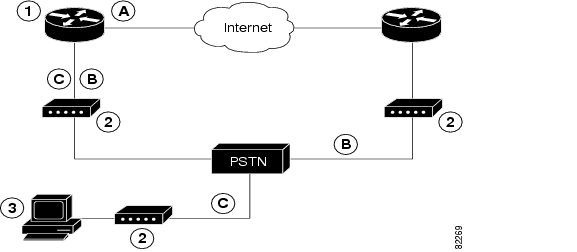
Figure 13-1 shows the network configuration used for remote management access and for providing backup to the primary WAN line.
Figure 13-1 Dial Backup and Remote Management Through the Auxiliary Port
Configuration Tasks
Perform these steps to configure dial backup and remote management for these routers, beginning in global configuration mode:
Step 1
ip name-server server-address
Example:
Router(config)# ip name-server 192.168.28.12Router(config)#Enters your ISP DNS IP address.
TipStep 2
ip dhcp pool name
Example:
Router(config)# ip dhcp pool 1Router(config-dhcp)#Creates a DHCP address pool on the router and enters DHCP pool configuration mode. The name argument can be a string or an integer.
•
Step 3
exit
Example:
Router(config-dhcp)# exitRouter(config)#Enters global configuration mode.
Step 4
chat-script script-name expect-send
Example:
Router(config)# chat-script Dialout ABORT ERROR ABORT BUSY "" "AT" OK "ATDT 5555102 T" TIMEOUT 45 CONNECT \cRouter(config)#Configures a chat script used in dial-on-demand routing (DDR) to give commands to dial a modem and to log in to remote systems. The defined script is used to place a call over a modem.
Step 5
interface type number
Example:
Router(config)# interface Async 1Router(config-if)#Creates and enters configuration mode for the asynchronous interface.
•
Step 6
exit
Example:
Router(config-if)# exitRouter(config)#Enters global configuration mode.
Step 7
interface type number
Example:
Router(config)# interface Dialer 3Router(config-if)#Enters interface configuration mode.
Step 8
dialer watch-group group-number
Example:
Router(config-if)# dialer watch-group 1Router(config-if)#Specifies the group number for watch list.
Step 9
exit
Example:
Router(config-if)# exitRouter(config)#Enters global configuration mode.
Step 10
ip nat inside source {list access-list-number} {interface type number | pool name} [overload]
Example:
Router(config)# ip nat inside source list 101 interface Dialer 3 overloadEnables dynamic translation of addresses on the inside interface.
Step 11
ip route prefix mask {ip-address | interface-type interface-number [ip-address]}
Example:
Router(config)# ip route 0.0.0.0 0.0.0.0 22.0.0.2Router(config)#Sets the IP route to point to the dialer interface as a default gateway.
Step 12
access-list access-list-number {deny | permit} source [source-wildcard]
Example:
Router(config)# access-list 1 permit
192.168.0.0 0.0.255.255 any
Defines an extended access list that indicates which addresses need translation.
Step 13
dialerwatch-list group-number {ip ip-address address-mask | delay route-check initial seconds}
Example:
Router(config)# dialer watch-list 1 ip 22.0.0.2 255.255.255.255Router(config)#Evaluates the status of the primary link, based on the existence of routes to the peer. 22.0.0.2 is the peer IP address of the ISP.
Step 14
line [aux | console | tty | vty] line-number [ending-line-number]
Example:
Router(config)# line console 0Router(config-line)#Enters configuration mode for the line interface.
Step 15
modem enable
Example:
Router(config-line)# modem enableRouter(config-line)#Switches the port from console to auxiliary port function.
Step 16
exit
Example:
Router(config-line)# exitRouter(config)#Enters global configuration mode.
Step 17
line [aux | console | tty | vty] line-number [ending-line-number]
Example:
Router(config)# line aux 0Router(config)#Enters configuration mode for the auxiliary interface.
Step 18
flowcontrol {none | software [lock] [in | out] | hardware [in | out]}
Example:
Router(config)# flowcontrol hardwareRouter(config)#Enables hardware signal flow control.
Configuration Example
The following configuration example specifies an IP address for the ATM interface through PPP/IPCP address negotiation and dial backup over the console port.
!ip name-server 192.168.28.12ip dhcp excluded-address 192.168.1.1!ip dhcp pool 1import allnetwork 192.168.1.0 255.255.255.0default-router 192.168.1.1!! Need to use your own correct ISP phone number.modemcap entry MY-USER_MODEM:MSC=&F1S0=1chat-script Dialout ABORT ERROR ABORT BUSY "" "AT" OK "ATDT 5555102\T"TIMEOUT 45 CONNECT \c!!!!interface vlan 1ip address 192.168.1.1 255.255.255.0ip nat insideip tcp adjust-mss 1452hold-queue 100 out!! Dial backup and remote management physical interface.interface Async1no ip addressencapsulation pppdialer in-banddialer pool-member 3async default routingasync dynamic routingasync mode dedicatedppp authentication pap callin!interface ATM0mtu 1492no ip addressno atm ilmi-keepalivepvc 0/35pppoe-client dial-pool-number 1!dsl operating-mode auto!! Primary WAN link.interface Dialer1ip address negotiatedip nat outsideencapsulation pppdialer pool 1ppp authentication pap callinppp pap sent-username account password 7 passppp ipcp dns requestppp ipcp wins requestppp ipcp mask request!! Dialer backup logical interface.interface Dialer3ip address negotiatedip nat outsideencapsulation pppno ip route-cacheno ip mroute-cachedialer pool 3dialer idle-timeout 60dialer string 5555102 modem-script Dialoutdialer watch-group 1!! Remote management PC IP address.peer default ip address 192.168.2.2no cdp enable!! Need to use your own ISP account and password.ppp pap sent-username account password 7 passppp ipcp dns requestppp ipcp wins requestppp ipcp mask request!! IP NAT over Dialer interface using route-map.ip nat inside source route-map main interface Dialer1 overloadip nat inside source route-map secondary interface Dialer3 overloadip classless!! When primary link is up again, distance 50 will override 80 if dial backup! has not timed out. Use multiple routes because peer IP addresses are alternated! among them when the CPE is connected.ip route 0.0.0.0 0.0.0.0 64.161.31.254 50ip route 0.0.0.0 0.0.0.0 66.125.91.254 50ip route 0.0.0.0 0.0.0.0 64.174.91.254 50ip route 0.0.0.0 0.0.0.0 63.203.35.136 80ip route 0.0.0.0 0.0.0.0 63.203.35.137 80ip route 0.0.0.0 0.0.0.0 63.203.35.138 80ip route 0.0.0.0 0.0.0.0 63.203.35.139 80ip route 0.0.0.0 0.0.0.0 63.203.35.140 80ip route 0.0.0.0 0.0.0.0 63.203.35.141 80ip route 0.0.0.0 0.0.0.0 Dialer1 150no ip http serverip pim bidir-enable!! PC IP address behind CPE.access-list 101 permit ip 192.168.0.0 0.0.255.255 anyaccess-list 103 permit ip 192.168.0.0 0.0.255.255 any!! Watch multiple IP addresses because peers are alternated! among them when the CPE is connected.dialer watch-list 1 ip 64.161.31.254 255.255.255.255dialer watch-list 1 ip 64.174.91.254 255.255.255.255dialer watch-list 1 ip 64.125.91.254 255.255.255.255!! Dial backup will kick in if primary link is not available! 5 minutes after CPE starts up.dialer watch-list 1 delay route-check initial 300dialer-list 1 protocol ip permit!! Direct traffic to an interface only if the dialer is assigned an IP address.route-map main permit 10match ip address 101match interface Dialer1!route-map secondary permit 10match ip address 103match interface Dialer3!! Change console to aux function.line con 0exec-timedout 0 0modem enablestopbits 1line aux 0exec-timeout 0 0! To enable and communicate with the external modem properly.script dialer Dialoutmodem InOutmodem autoconfigure discoverytransport input allstopbits 1speed 115200flowcontrol hardwareline vty 0 4exec-timeout 0 0password ciscologin!scheduler max-task-time 5000endConfiguring Dial Backup and Remote Management Through the ISDN S/T Port
Cisco 876 and Cisco 878 routers can use the ISDN S/T port for remote management. With an advanced enterprise (c870-adventerprisek9-mz) image, a Cisco 876 router can also use the ISDN S/T port for dial backup.
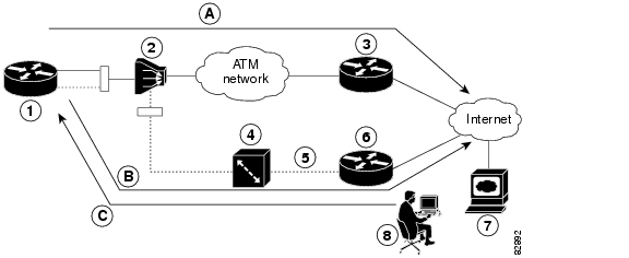
Figure 13-2 and Figure 13-3 show two typical network configurations used to provide remote management access and backup for the primary WAN line. In Figure 13-2, the dial backup link goes through a customer premises equipment (CPE) splitter, a digital subscriber line access multiplexer (DSLAM), and a central office (CO) splitter before connecting to the ISDN switch. In Figure 13-3, the dial backup link goes directly from the Cisco router to the ISDN switch.
Figure 13-2 Dial Backup Through CPE Splitter, DSLAM, and CO Splitter
Figure 13-3 Dial Backup Directly from Router to ISDN Switch
Configuration Tasks
Perform the following tasks to configure dial backup and remote management through the ISDN S/T port of your router:
•
Configure ISDN Settings
Note
Perform these steps to configure your router ISDN interface for use as a backup interface, beginning in global configuration mode:
Step 1
isdn switch-type switch-type
Example:
Router(config)# isdn switch-type basic-net3Router(config)#Specifies the ISDN switch type.
The example specifies a switch type used in Australia, Europe, and the United Kingdom. For details on other switch types supported, see the Cisco IOS Dial Technologies Command Reference.
Step 2
interface type number
Example:
Router(config)# interface bri 0Router(config-if)#Enters configuration mode for the ISDN Basic Rate Interface (BRI).
Step 3
encapsulation encapsulation-type
Example:
Router(config-if)# encapsulation pppRouter(config-if)#Sets the BRI0 interface encapsulation type.
Step 4
dialer pool-member number
Example:
Router(config-if)# dialer pool-member 1Router(config-if)#Specifies the dialer pool membership.
Step 5
isdn switch-type switch-type
Example:
Router(config-if)# isdn switch-type basic-net3Router(config-if)#Specifies the ISDN switch type.
Step 6
exit
Example:
Router(config-if)# exitRouter(config)#Enters global configuration mode.
Step 7
interface dialer dialer-rotary-group-number
Example:
Router(config)# interface dialer 0Router(config-if)#Creates a dialer interface (numbered 0-255) and enters interface configuration mode.
Step 8
ip address negotiated
Example:
Router(config-if)# ip address negotiatedRouter(config-if)#Specifies that the IP address for the interface is obtained through PPP/IPCP (IP Control Protocol) address negotiation. The IP address is obtained from the peer.
Step 9
encapsulation encapsulation-type
Example:
Router(config-if)# encapsulation pppRouter(config-if)#Sets the encapsulation type to PPP for the interface.
Step 10
dialer pool number
Example:
Router(config-if)# dialer pool 1Router(config-if)#Specifies the dialer pool to be used.
In the example, the dialer pool 1 setting associates the dialer 0 interface with the BRI0 interface because the BRI0 dialer pool-member value is 1.
Step 11
dialer string dial-string[:isdn-subaddress]
Example:
Router(config-if)# dialer string 384040Router(config-if)#Specifies the telephone number to be dialed.
Step 12
dialer-group group-number
Example:
Router(config-if)# dialer group 1Router(config-if)#Assigns the dialer interface to a dialer group (1-10).
Step 13
exit
Example:
Router(config-if)# exitRouter(config)#Exits dialer 0 interface configuration mode, and enters global configuration mode.
Step 14
dialer-list dialer-group protocol protocol-name {permit | deny | list access-list-number | access-group}
Example:
Router(config)# dialer-list 1 protocol ip permitRouter(config)#Creates a dialer list for packets of interest to be forwarded through the specified interface dialer group.
In the example, dialer-list 1 corresponds to dialer-group 1.
For details about this command and additional parameters that can be set, see the Cisco IOS Dial Technologies Command Reference.
Configure the Aggregator and ISDN Peer Router
The aggregator is typically a concentrator router where your Cisco router ATM PVC terminates. In the configuration example shown below, the aggregator is configured as a PPPoE server to correspond with the Cisco 876 router configuration example that is given in this chapter.
The ISDN peer router is any router that has an ISDN interface and can communicate through a public ISDN network to reach your Cisco router ISDN interface. The ISDN peer router provides Internet access for your Cisco router during the ATM network downtime.
! This portion of the example configures the aggregator.vpdn enableno vpdn logging!vpdn-group 1accept-dialinprotocol pppoevirtual-template 1!interface Ethernet3description "4700ref-1"ip address 40.1.1.1 255.255.255.0media-type 10BaseT!interface Ethernet4ip address 30.1.1.1 255.255.255.0media-type 10BaseT!interface Virtual-Template1ip address 22.0.0.2 255.255.255.0ip mtu 1492peer default ip address pool adsl!interface ATM0no ip addresspvc 1/40encapsulation aal5snapprotocol pppoe!no atm limi-keepalive!ip local pool adsl 22.0.0.1ip classlessip route 0.0.0.0 0.0.0.0 22.0.0.1 50ip route 0.0.0.0 0.0.0.0 30.1.1.2.80! This portion of the example configures the ISDN peer.isdn switch-type basic-net3!interface Ethernet0ip address 30.1.1.2 255.0.0.0!interface BRI0description "to 836-dialbackup"no ip addressencapsulation pppdialer pool-member 1isdn switch-type basic-net3!interface Dialer0ip address 192.168.2.2 255.255.255.0encapsulation pppdialer pool 1dialer string 384020dialer-group 1peer default ip address pool isdn!ip local pool isdn 192.168.2.1ip http serverip classlessip route 0.0.0.0 0.0.0.0 192.168.2.1ip route 40.0.0.0 255.0.0.0 30.1.1.1!dialer-list 1 protocol ip permit!