-
Cisco 850 Series and Cisco 870 Series Access Routers Cabling and Setup Quick Start Guide
-
Cisco 850 Series and Cisco 870 Series Access Routers Cabling and Setup Quick Start Guide (English)
-
Cisco 850 Series and Cisco 870 Series Access Routers Cabling and Setup Quick Start Guide (Deutsch)
-
Cisco 850 Series and Cisco 870 Series Access Routers Cabling and Setup Quick Start Guide (Nederlands)
-
Cisco 850 Series and Cisco 870 Series Access Routers Cabling and Setup Quick Start Guide (Français)
-
Cisco 850 Series and Cisco 870 Series Access Routers Cabling and Setup Quick Start Guide (Italiano)
-
Cisco 850 Series and Cisco 870 Series Access Routers Cabling and Setup Quick Start Guide (Español)
-
 Feedback
Table Of Contents
Cisco 850 Series and Cisco 870 Series Access Routers Cabling and Setup Quick Start Guide
Cisco One-Year Limited Hardware Warranty Terms
Locate the Product Serial Number
Check Items Shipped with the Router
Read the Safety Warnings and Guidelines
Connect the Antenna to the Wireless Router (Optional)
Connect the Power-over-Ethernet Module to the Cisco 870 Series Router (Optional)
Typical Installations of the Cisco 850 Series and Cisco 870 Series Routers
Install SDM and Configure the Router
Obtaining Documentation and Submitting a Service Request
Cisco 850 Series and Cisco 870 Series Access Routers Cabling and Setup Quick Start Guide
Contents
•
Cisco One-Year Limited Hardware Warranty Terms
•
•
•
•
•
•
Cisco One-Year Limited Hardware Warranty Terms
The following are special terms applicable to your hardware warranty. Your formal Warranty Statement, including the warranty applicable to Cisco software, appears in the Cisco Information Packet that accompanies your Cisco product.
Duration of Hardware Warranty: One (1) Year
Replacement, Repair or Refund Procedure for Hardware: Cisco or its service center will use commercially reasonable efforts to ship a replacement part within ten (10) working days after receipt of the RMA request. Actual delivery times may vary depending on Customer location.
Cisco reserves the right to refund the purchase price as its exclusive warranty remedy.
To Receive a Return Materials Authorization (RMA) Number: Please contact the party from whom you purchased the product. If you purchased the product directly from Cisco, contact your Cisco Sales and Service Representative.
Complete the form below and keep for ready reference.
Product purchased from:
Their telephone number:
Product Model and Serial number:
Maintenance Contract number:
Product warranty terms and other information applicable to Cisco products are available at the following URL:
http://www.cisco.com/go/warranty
Locate the Product Serial Number
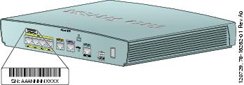
The serial number label for the router is located on the rear of the chassis, above the Ethernet LAN ports. (See Figure 1-1.)
Figure 1-1 Product Serial Number Location
Before Installation
•
•
Check Items Shipped with the Router
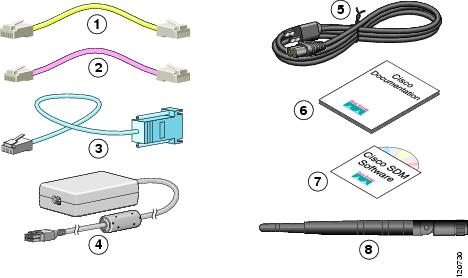
Table 1-1 lists the quantity of the items that are shipped with each router model in the Cisco 850 series and the Cisco 870 series routers. Figure 1-2 depicts the items.
Verify that the items listed in Table 1-1 were shipped with the router. If any of the items is missing or damaged, contact your customer service representative.
Table 1-1 Items Shipped with Cisco 850 Series and Cisco 870 Series Routers
Ethernet cable (straight-through)
1
1
1
1
DSL1 cable
Not applicable
12
13
13
ISDN4 S/T cable
Not applicable
Not applicable
Optional
Optional
Console cable
1
1
1
1
Console-auxiliary5 cable
Optional
Optional
Optional
Optional
Power adapter
1
1
1
1
Power cord6
1
1
1
1
Cisco documentation7
1
1
1
1
Cisco Router and Security Device Manager (SDM) software CD
1
1
1
1
Swivel-mount dipole antenna (wireless router models only)
Cisco 851: 1 antenna
Cisco 871: 2 antennas
Cisco 857: 1 antenna
Cisco 877: 2 antennas
2
2
1 DSL = digital subscriber line. Used for an asynchronous digital subscriber line (ADSL) or multirate symmetrical high-data-rate digital subscriber line (G.SHDSL).
2 An RJ-11-to-RJ-11 straight-through cable is shipped, unless an RJ-11-to-RJ-11 crossover cable is specified.
3 An RJ-11-to-RJ-11 straight-through cable is shipped, unless an RJ-11-to-RJ-11 crossover cable or an RJ-11-to-RJ-45 cable is specified.
4 ISDN = Integrated Services Digital Network.
5 Console-auxiliary cable is used to connect the router console port to an asynchronous modem for dial backup or remote management.
6 Power cords are ordered as applicable to country or geographic region.
7 Includes the Regulatory Compliance and Safety Information for Cisco 800 Series Routers document and the Cisco 850 Series and Cisco 870 Series Access Routers Cabling and Setup Quick Start Guide (this document). Also includes the Declarations of Conformity and Regulatory Information for Cisco Access Products with 802.11a/b/g and 802.11b/g Radios document for wireless models.
Figure 1-2 Items Included with the Cisco 850 Series and Cisco 870 Series Routers
The following cables are not included with the router. You need to order them separately.
•
•
Caution
Nonwireless Routers
Portions of this guide do not apply to nonwireless models of the Cisco 850 series and Cisco 870 series routers. Some illustrations show the router with antennas attached, whereas the nonwireless routers do not have antennas or antenna connectors on the back panel. However, except for the "Connect the Antenna to the Wireless Router (Optional)" section, the connection procedures are the same for wireless and nonwireless router models.
Read the Safety Warnings and Guidelines
Before you begin to connect your router, read the Regulatory Compliance and Safety Information for Cisco 800 Series Routers document that is shipped with the router. This document provides important safety warnings and guidelines.
Remove the Caution Sticker
Locate the yellow caution label that covers the LAN ports. Simply peel off the label and the LAN ports are ready for use. Be sure that you do not connect ISDN telephone lines to these LAN ports.
Connect the Antenna to the Wireless Router (Optional)
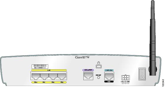
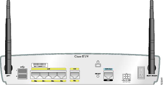
The Cisco 850 series wireless routers support the use of a single 2.4-GHz antenna. (See Figure 1-3.) The Cisco 870 series wireless routers support the use of two 2.4-GHz antennas. (See Figure 1-4.)
Figure 1-3 Cisco 857 Wireless Router with Single Antenna
Figure 1-4 Cisco 871 Wireless Router with Two Antennas
To connect the antenna or antennas to a wireless router, follow these steps:
Step 1
Step 2
Connect the Power-over-Ethernet Module to the Cisco 870 Series Router (Optional)
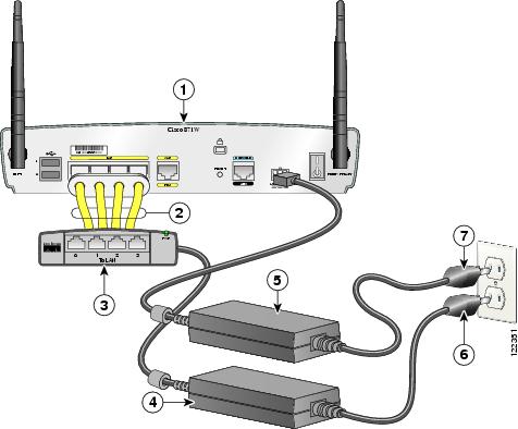
Power-over-Ethernet (PoE) is supported on the Cisco 870 Series routers only. If you purchased a PoE module, connect all four Ethernet cables on the PoE module to the four LAN Ethernet ports on the Cisco 870 Series router. (See Figure 1-5.) Make sure that you connect all four Ethernet cables.
If the cables are too close together for easy insertion, move the plastic cable guard away from the connector end of the cables.
Caution
Although Figure 1-5 shows the Cisco 871 router connected to a PoE module, this connection works for all router models in the Cisco 870 series.
Note
Figure 1-5 Connecting the PoE Module to the Router
Cisco 870 series router
Router power adapter
Ethernet cables on the PoE module (four RJ-45 connectors in series)
PoE power plug
PoE module
Router power plug
PoE power adapter
Typical Installations of the Cisco 850 Series and Cisco 870 Series Routers
Typical installations of the Cisco 850 series and Cisco 870 series routers are depicted in Figure 1-6 through Figure 1-9, as follows:
•
•
•
•
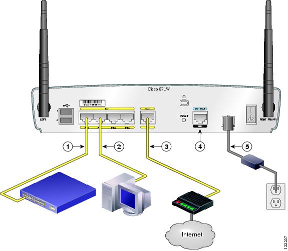
Figure 1-6 shows a typical installation of a Cisco 851 or Cisco 871 router. This figure shows the back panel of a Cisco 871 router, which has two Universal Serial Bus (USB) ports. The Cisco 851 router does not have any USB ports; however, the connections on the other ports are the same for both the Cisco 851 and the Cisco 871 routers.
Figure 1-6 Typical Installation of a Cisco 851 or Cisco 871 Router
Ethernet connection to an external switch
Console port
Ethernet connection to a PC
Power adapter
WAN connection using a broadband modem to the Internet
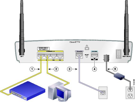
Figure 1-7 shows a typical installation of a Cisco 857 or Cisco 877 router.
Figure 1-7 Typical Installation of a Cisco 857 or a Cisco 877 Router
Ethernet connection to an external switch
Console port
Ethernet connection to a PC
Power adapter
ADSL-over-POTS connection
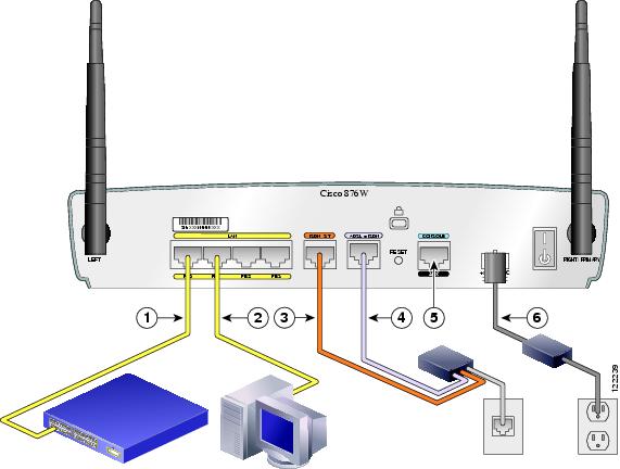
Figure 1-8 shows a typical installation of a Cisco 876 router.
Figure 1-8 Typical Installation of a Cisco 876 Router
Ethernet connection to an external switch
ADSL-over-ISDN connection
Ethernet connection to a PC
Console port
ISDN S/T connection
Power adapter
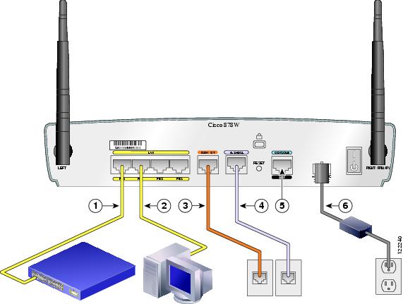
Figure 1-9 shows a typical installation of a Cisco 878 router.
Figure 1-9 Typical Installation of a Cisco 878 Router
Ethernet connection to an external switch
G.SHDSL connection
Ethernet connection to a PC
Console port
ISDN S/T connection
Power adapter
Connect the Router
Connect the router, referring to the typical installation for your router model as shown in the "Typical Installations of the Cisco 850 Series and Cisco 870 Series Routers" section.
Follow these steps to connect the router to the power supply, to your local network, and to your service provider:
Step 1
Step 2
Step 3
Step 4
Step 5
Note
Step 6
Follow the instructions provided with your broadband modem to determine which port on the modem to connect to. Turn on the broadband modem if it is not already turned on.
Step 7
Step 8
Caution
Step 9
Step 10
Step 11
Step 12
The green OK LED on the front panel of the router lights up when you connect the router to a power source. The router is now ready for use.
If the green OK LED does not turn on, see the "Troubleshooting" chapter in the Cisco 850 Series and Cisco 870 Series Routers Hardware Installation Guide.
Note
Step 13
See the Cisco 870 Series Routers Hardware Installation Guide for detailed connection instructions.
Install SDM and Configure the Router
To install Cisco SDM for configuring the router, follow these steps:
Step 1
Step 2
Step 3
Related Documentation
This document describes the basic process of cabling and setting up the Cisco 850 series and Cisco 870 series routers. See the following documents for more information:
•
•
•
•
•
•
•
These documents are available on the World Wide Web. You can access the most current Cisco documentation on the World Wide Web at the following sites:
Obtaining Documentation and Submitting a Service Request
For information on obtaining documentation, submitting a service request, and gathering additional information, see the monthly What's New in Cisco Product Documentation, which also lists all new and revised Cisco technical documentation, at:
http://www.cisco.com/en/US/docs/general/whatsnew/whatsnew.html
Subscribe to the What's New in Cisco Product Documentation as a Really Simple Syndication (RSS) feed and set content to be delivered directly to your desktop using a reader application. The RSS feeds are a free service and Cisco currently supports RSS Version 2.0.