Feedback Feedback
|
Table Of Contents
Installing and Removing Field-Replaceable Memory in Cisco IAD2420 Series Integrated Access Devices
Preventing Electrostatic Discharge Damage
Memory and Software Upgrade Tasks
Replacing System-Code Flash Memory
System-Code Flash Memory Configurations
Replacing the Flash Memory SIMM
Installing a Cisco IOS Image in Flash Memory
Obtaining Technical Assistance
Installing and Removing Field-Replaceable Memory in Cisco IAD2420 Series Integrated Access Devices
Product Numbers:
MEM-240-1X16F=, MEM-240-1X32F=This document provides instructions for installing and removing single in-line memory modules (SIMMs) in the Cisco IAD2420 series integrated access devices (IADs).
This document includes procedures for:
•
Upgrading the memory modules
•
Use this document in conjunction with the following documents:
•
•
•
•
If you have questions or need help, see the "Obtaining Documentation" section and the "Obtaining Technical Assistance" section.
This document contains the following sections:
•
•
•
Safety Recommendations
Safety Warnings
Warning
Waarschuwing Dit waarschuwingssymbool betekent gevaar. U verkeert in een situatie die lichamelijk letsel kan veroorzaken. Voordat u aan enige apparatuur gaat werken, dient u zich bewust te zijn van de bij elektrische schakelingen betrokken risico's en dient u op de hoogte te zijn van standaard maatregelen om ongelukken te voorkomen. Voor vertalingen van de waarschuwingen die in deze publicatie verschijnen, kunt u het document Regulatory Compliance and Safety Information (Informatie over naleving van veiligheids- en andere voorschriften) raadplegen dat bij dit toestel is ingesloten.
Varoitus Tämä varoitusmerkki merkitsee vaaraa. Olet tilanteessa, joka voi johtaa ruumiinvammaan. Ennen kuin työskentelet minkään laitteiston parissa, ota selvää sähkökytkentöihin liittyvistä vaaroista ja tavanomaisista onnettomuuksien ehkäisykeinoista. Tässä julkaisussa esiintyvien varoitusten käännökset löydät laitteen mukana olevasta Regulatory Compliance and Safety Information -kirjasesta (määräysten noudattaminen ja tietoa turvallisuudesta).
Attention Ce symbole d'avertissement indique un danger. Vous vous trouvez dans une situation pouvant causer des blessures ou des dommages corporels. Avant de travailler sur un équipement, soyez conscient des dangers posés par les circuits électriques et familiarisez-vous avec les procédures couramment utilisées pour éviter les accidents. Pour prendre connaissance des traductions d'avertissements figurant dans cette publication, consultez le document Regulatory Compliance and Safety Information (Conformité aux règlements et consignes de sécurité) qui accompagne cet appareil.
Warnung Dieses Warnsymbol bedeutet Gefahr. Sie befinden sich in einer Situation, die zu einer Körperverletzung führen könnte. Bevor Sie mit der Arbeit an irgendeinem Gerät beginnen, seien Sie sich der mit elektrischen Stromkreisen verbundenen Gefahren und der Standardpraktiken zur Vermeidung von Unfällen bewußt. Übersetzungen der in dieser Veröffentlichung enthaltenen Warnhinweise finden Sie im Dokument Regulatory Compliance and Safety Information (Informationen zu behördlichen Vorschriften und Sicherheit), das zusammen mit diesem Gerät geliefert wurde.
Avvertenza Questo simbolo di avvertenza indica un pericolo. La situazione potrebbe causare infortuni alle persone. Prima di lavorare su qualsiasi apparecchiatura, occorre conoscere i pericoli relativi ai circuiti elettrici ed essere al corrente delle pratiche standard per la prevenzione di incidenti. La traduzione delle avvertenze riportate in questa pubblicazione si trova nel documento Regulatory Compliance and Safety Information (Conformità alle norme e informazioni sulla sicurezza) che accompagna questo dispositivo.
Advarsel Dette varselsymbolet betyr fare. Du befinner deg i en situasjon som kan føre til personskade. Før du utfører arbeid på utstyr, må du vare oppmerksom på de faremomentene som elektriske kretser innebærer, samt gjøre deg kjent med vanlig praksis når det gjelder å unngå ulykker. Hvis du vil se oversettelser av de advarslene som finnes i denne publikasjonen, kan du se i dokumentet Regulatory Compliance and Safety Information (Overholdelse av forskrifter og sikkerhetsinformasjon) som ble levert med denne enheten.
Aviso Este símbolo de aviso indica perigo. Encontra-se numa situação que lhe poderá causar danos físicos. Antes de começar a trabalhar com qualquer equipamento, familiarize-se com os perigos relacionados com circuitos eléctricos, e com quaisquer práticas comuns que possam prevenir possíveis acidentes. Para ver as traduções dos avisos que constam desta publicação, consulte o documento Regulatory Compliance and Safety Information (Informação de Segurança e Disposições Reguladoras) que acompanha este dispositivo.
¡Advertencia! Este símbolo de aviso significa peligro. Existe riesgo para su integridad física. Antes de manipular cualquier equipo, considerar los riesgos que entraña la corriente eléctrica y familiarizarse con los procedimientos estándar de prevención de accidentes. Para ver una traducción de las advertencias que aparecen en esta publicación, consultar el documento titulado Regulatory Compliance and Safety Information (Información sobre seguridad y conformidad con las disposiciones reglamentarias) que se acompaña con este dispositivo.
Varning! Denna varningssymbol signalerar fara. Du befinner dig i en situation som kan leda till personskada. Innan du utför arbete på någon utrustning måste du vara medveten om farorna med elkretsar och känna till vanligt förfarande för att förebygga skador. Se förklaringar av de varningar som förkommer i denna publikation i dokumentet Regulatory Compliance and Safety Information (Efterrättelse av föreskrifter och säkerhetsinformation), vilket medföljer denna anordning.
Warning
Warning
Warning
Warning
Warning
Warning
Safety with Electricity
Follow these guidelines when working on equipment powered by electricity:
Warning
•
•
–
–
–
•
•
•
•
–
–
–
–
Preventing Electrostatic Discharge Damage
Electrostatic discharge (ESD) can damage equipment and impair electrical circuitry. It occurs when electronic printed circuit cards are improperly handled and can result in complete or intermittent failures. Always follow ESD prevention procedures when removing and replacing cards. Ensure that the chassis is electrically connected to earth ground. Wear an ESD-preventive wrist strap, ensuring that it makes good skin contact. Connect the clip to an unpainted surface of the chassis frame to safely channel unwanted ESD voltages to ground. To properly guard against ESD damage and shocks, the wrist strap and cord must operate effectively. If no wrist strap is available, ground yourself by touching the metal part of the chassis.
Caution
Caution
Required Tools and Equipment
You need the following tools and equipment to remove and install memory modules in a Cisco IAD:
•
•
•
•
Memory and Software Upgrade Tasks
If you upgrade your Cisco IOS software to a later release, it may be necessary to increase the size of Flash memory.
For memory module installation instructions, see the applicable procedure as follows:
•
•
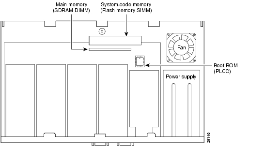
Figure 1 shows the physical locations of the replaceable memory components.
Figure 1 Memory Locations in Cisco IAD2420 Series IADs
Replacing System-Code Flash Memory
The system code (software) is stored on a Flash memory SIMM. It might be necessary to increase the system-code Flash memory if you are upgrading to software with more features.
The show version command allows you to see the amount of system-code Flash memory in KB. The following example shows a system with 8 MB of system-code Flash memory. The amount of system-code Flash memory (8192 KB) is shown on the next to last line of this example.
Cisco Internetwork Operating System SoftwareIOS (tm) IAD2420 Software (C2420-A2I8SV5-M), Version 12.1
Copyright (c) 1986-2001 by cisco Systems, Inc.
(Multiple lines omitted for brevity)
256K bytes of non-volatile configuration memory.8192K bytes of processor board System flash (INTEL28F016)Configuration register is 0x100System-Code Flash Memory Configurations
Cisco IAD2420 series IADs contain one Flash memory SIMM socket that holds a single 8-, 16-, or 32-MB Flash memory SIMM. Flash memory of 8, 16, or 32 MB may be required, depending on the size of the Cisco IOS software image.
To load two simultaneous images of software, at least 16 or 32 MB of Flash memory may be required, depending on the image size. To increase Flash memory capacity, you must remove the existing Flash memory SIMM and install a SIMM of the required capacity.
Note
Table 1 lists the available Flash memory SIMMs. Order system-code memory from Cisco Systems.
Table 1 Flash Memory SIMM Memory Configurations
16 MB
MEM-240-1X16F=
32 MB
MEM-240-1X32F=
Replacing the Flash Memory SIMM
Caution
Step 1
Caution
Tips
Step 2
Step 3
Step 4
Caution
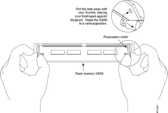
Figure 2 Releasing Latches on a Flash Memory SIMM
Step 5
Caution
Step 6
Step 7
If error messages relating to memory are displayed, repeat Step 2 through Step 7, taking care to seat the Flash memory SIMM firmly in its socket.
Step 8
Installing a Cisco IOS Image in Flash Memory
Follow this procedure to copy a Cisco IOS image from a TFTP server to the Cisco IAD2420 series IAD Flash memory if the Flash memory SIMM does not have an installed Cisco IOS image.
If your system already has a Cisco IOS image in Flash memory, follow the procedure in the "Copy an Image from a TFTP Server to a Flash Memory File System" section of the appropriate Configuration Fundamentals Configuration Guide, for Cisco IOS Release 12.1 or 12.2.
Step 1
If necessary turn the power ON. If there is no Cisco IOS image in the Flash memory, the system displays a boot fail message and then boots with a ROM monitor prompt (rommon 1>).
Step 2
Reboots the system to the boot helper image.
Step 3
Enters privileged EXEC mode.
Step 4
Copies the Cisco IOS image from a TFTP server to the system Flash memory.
Step 5
You will be prompted to enter the following information:
•
•
•
The Cisco IOS image is copied into Flash memory.
Step 6
(Optional) Verifies that the new Cisco IOS image (filename) is in the system Flash memory.
Step 7
(Optional) Enters global configuration mode, if you need to change the configuration register. Normally the default configuration register is used. See the show version output on page 7 to determine the existing configuration register.
Step 8
(Optional) Specifies a configuration register.
Step 9
(Optional) Exits from global configuration mode, if you changed the configuration register
Step 10
Reboots the system with the new Cisco IOS image.
Step 11
(Optional) Saves the configuration with the new configuration register. This message appears only if you entered global configuration mode in Step 7.
Step 12
(Optional) This message appears only if you have changed the configuration register. Press RETURN to confirm.
Step 13
Press RETURN to confirm the reboot.
Step 14
Press RETURN to bring up a router prompt.
Step 15
Procedure finished; system is running Cisco IOS software.
The following example copies a Cisco IOS image (c2400-a2i8sv5-mz) from a TFTP server to a 32-MB system Flash memory on a Cisco IAD2420 series IAD:
rommon 1> bootRouter(boot)> enableRouter(boot)# copy tftp flashAddress or name of remote host []? <Ethernet address of remote host>Source filename []? <directory>/c2400-a2i8sv5-mzDestination filename [c2400-a2i8sv5-mz]?Accessing tftp://<Ethernet address of remote host>/<directory>/c2400-a2i8sv5-mz...Loading <directory>/c2400-a2i8sv5-mz from <Ethernet address of remote host> (via Ethernet0): !!!!!!!!!!!!!!!!!!!!!!!!!!!!!!!!!!!!!!!!!!!!!!!!!!!!!!!!!!!!!!!!!!!!!!!!!!!!!!!!!!!!!!!!! !!!!!!!!!!!!!!!!!!!!!!!!!!!!!!!!!!!!!!!!!!!!!!!!!!!!!!!!!!!!!!!!!!!!!!!!!!!!!!!!!!!!!!!!! !!!!!!!!!!!!!!!!!!!!!!!!!!!!!!!!!!!!!!!!!!!!!!!!!!!!!!!!!!!!!!!!!!!!!!!!!!!!!!!!!!!!!!!!! !!!!!!!!!!!!!!!!!!!!!!!!!!!!!!!!!!!!!!!!!!!!!!!!!!!!!!!!!!!![OK - 7192884/14385152 bytes]7192884 bytes copied in 237.472 secs (30349 bytes/sec)Router(boot)# show flash32768K bytes of processor board System flash (INTEL28F640)Directory of flash:/2 -rwx 7192884 Mar 01 1993 00:10:45 c2400-a2i8sv5-mz4 -rwx 1990 Mar 01 1993 05:57:57 gr3035 -rwx 2133 Mar 01 1993 17:03:18 gr303.18128000 bytes total (929280 bytes free)Router(boot)# reloadProceed with reload? [confirm]00:06:44: %SYS-5-RELOAD: Reload requestedIAD2420 CPU restarted, RSR=E8000000, reason(s):,loss of PLL,checkstop resetSystem Bootstrap, Version 12.1(5r)XR1, RELEASE SOFTWARECopyright (c) 2000 by cisco Systems, Inc.Compiled Thu 09-Nov-00 09:37 by ccaiMPC860P-80MHz PowerQUICC, partnum 0x0005, version X01(0x0001)IAD2420 platform with 65536 Kbytes of main memoryprogram load complete, entry point:0x23000, size:0x116c4cSelf decompressing the image :######################################################################################### ################################################[OK]%SYS-7-NV_BLOCK_INIT:Initalized the geometry of nvramSlot 3 OK.Configured as T1 TEB CSU Serial #18947625 Version 7.03Initialize Flash file system.....total size = 8388608flashfs[8]:3 files, 1 directoriesflashfs[8]:0 orphaned files, 0 orphaned directoriesflashfs[8]:Total bytes:8128000flashfs[8]:Bytes used:7198720flashfs[8]:Bytes available:929280flashfs[8]:flashfs fsck took 8 seconds.flashfs[8]:Initialization complete.%PARSER-4-BADCFG:Unexpected end of configuration file.%SYS-6-BOOT_MESSAGES:Messages above this line are from the boot loader.%CONTROLLER-5-UPDOWN:Controller T1 0, changed state to upUART re-init OK (disable AUX port)program load complete, entry point:0x23000, size:0x6dc018Self decompressing the image :######################################################################################### ######################################################################################### ######################################################################################### ######################################################################################### ######################################################################################### ######################################################################################### ######################################################################################### ######################################################################################### ######################################################################################### #########################################[OK]Restricted Rights LegendUse, duplication, or disclosure by the Government issubject to restrictions as set forth in subparagraph(c) of the Commercial Computer Software - RestrictedRights clause at FAR sec. 52.227-19 and subparagraph(c) (1) (ii) of the Rights in Technical Data and ComputerSoftware clause at DFARS sec. 252.227-7013.cisco Systems, Inc.170 West Tasman DriveSan Jose, California 95134-1706Cisco Internetwork Operating System SoftwareIOS (tm) IAD2420 Software (C2420-A2I8SV5-M), RELEASE SOFTWARE12.1(20010606:230705) [sheaunt-yd10 112]Copyright (c) 1986-2001 by cisco Systems, Inc.Compiled Fri 13-Jul-01 17:34 by sheauntImage text-base:0x00023000, data-base:0x00D5ADBCSlot 3 OK. Configured as T1 TEB CSU Serial #18947625 Version 7.03Cisco IAD2420 (MPC860P) processor (revision 18.04) with 57344K/8192Kbytes of memory.Processor board ID 13034670PPC860 PowerQUICC, partnum 0x0005, version X01(0x0001)Channelized E1, Version 1.0.Bridging software.Primary Rate ISDN software, Version 1.1.IAD2420 SCB board (v01.B0), FPGA version 0.61 Multiflex T1(slot 3) RJ45 interface(v03.A0)1 Six-Slot Analog Voice Module (v07.B0)1 Analog FXS voice interface (v03.E0) port 1/11 Analog FXS voice interface (v03.E0) port 1/21 Analog FXS voice interface (v03.E0) port 1/31 Analog FXS voice interface (v03.E0) port 1/41 Analog FXS voice interface (v03.E0) port 1/51 Analog FXS voice interface (v03.E0) port 1/61 6-DSP(slot2) High Performance Compression Module(v01.A0)1 Ethernet/IEEE 802.3 interface(s)1 Serial(sync/async) network interface(s)1 terminal line(s)1 Channelized T1/PRI port(s)256K bytes of non-volatile configuration memory.8192K bytes of processor board System flash (INTEL28F016)Press RETURN to get started!A series of messages is displayed. Press RETURN at any time to bring up the router prompt. Your IAD is now ready for operation or reconfiguration.
Router>Opening the Chassis
This section explains how to open the chassis by removing the chassis cover.
Warning
Warning
Warning
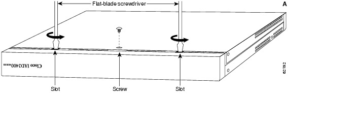
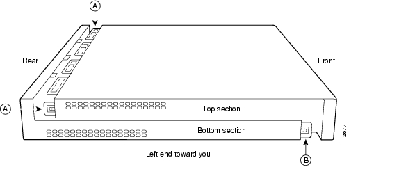
Refer to Parts A and B in Figure 3 and follow these steps to remove the chassis cover:
Step 1
Warning
Step 2
Step 3
Step 4
Step 5
Step 6
Step 7
Step 8
Figure 3 Chassis Cover Removal—Parts A (Top) and B (Bottom)
Closing the Chassis
This section describes how to close the chassis by installing the cover.
Step 1
Step 2
•
•
Caution
Figure 4 Installing the Chassis Cover
Step 3
Step 4
Step 5
Step 6
Step 7
Obtaining Documentation
World Wide Web
You can access the most current Cisco documentation on the World Wide Web at http://www.cisco.com, http://www-china.cisco.com, or http://www-europe.cisco.com.
Documentation CD-ROM
Cisco documentation and additional literature are available in a CD-ROM package, which ships with your product. The Documentation CD-ROM is updated monthly. Therefore, it is probably more current than printed documentation. The CD-ROM package is available as a single unit or as an annual subscription.
Ordering Documentation
Registered CCO users can order the Documentation CD-ROM and other Cisco Product documentation through our online Subscription Services at http://www.cisco.com/cgi-bin/subcat/kaojump.cgi.
Nonregistered CCO users can order documentation through a local account representative by calling Cisco's corporate headquarters (California, USA) at 408 526-4000 or, in North America, call 800 553-NETS (6387).
Documentation Feedback
If you are reading Cisco product documentation on the World Wide Web, you can submit technical comments electronically. Click Feedback in the toolbar and select Documentation. After you complete the form, click Submit to send it to Cisco.
You can e-mail your comments to bug-doc@cisco.com.
To submit your comments by mail, for your convenience many documents contain a response card behind the front cover. Otherwise, you can mail your comments to the following address:
Cisco Systems, Inc.
Document Resource Connection
170 West Tasman Drive
San Jose, CA 95134-9883We appreciate and value your comments.
Obtaining Technical Assistance
Cisco provides Cisco.com as a starting point for all technical assistance. Customers and partners can obtain documentation, troubleshooting tips, and sample configurations from online tools by using the Cisco Technical Assistance Center (TAC) Web Site. Cisco.com registered users have complete access to the technical support resources on the Cisco TAC Web Site.
Cisco.com
Cisco.com is the foundation of a suite of interactive, networked services that provides immediate, open access to Cisco information, networking solutions, services, programs, and resources at any time, from anywhere in the world.
Cisco.com is a highly integrated Internet application and a powerful, easy-to-use tool that provides a broad range of features and services to help you to
•
•
•
•
•
You can self-register on Cisco.com to obtain customized information and service. To access Cisco.com, go to the following URL:
Technical Assistance Center
The Cisco TAC is available to all customers who need technical assistance with a Cisco product, technology, or solution. Two types of support are available through the Cisco TAC: the Cisco TAC Web Site and the Cisco TAC Escalation Center.
Inquiries to Cisco TAC are categorized according to the urgency of the issue:
•
•
•
•
Which Cisco TAC resource you choose is based on the priority of the problem and the conditions of service contracts, when applicable.
Cisco TAC Web Site
The Cisco TAC Web Site allows you to resolve P3 and P4 issues yourself, saving both cost and time. The site provides around-the-clock access to online tools, knowledge bases, and software. To access the Cisco TAC Web Site, go to the following URL:
All customers, partners, and resellers who have a valid Cisco services contract have complete access to the technical support resources on the Cisco TAC Web Site. The Cisco TAC Web Site requires a Cisco.com login ID and password. If you have a valid service contract but do not have a login ID or password, go to the following URL to register:
http://www.cisco.com/register/
If you cannot resolve your technical issues by using the Cisco TAC Web Site, and you are a Cisco.com registered user, you can open a case online by using the TAC Case Open tool at the following URL:
http://www.cisco.com/tac/caseopen
If you have Internet access, it is recommended that you open P3 and P4 cases through the Cisco TAC Web Site.
Cisco TAC Escalation Center
The Cisco TAC Escalation Center addresses issues that are classified as priority level 1 or priority level 2; these classifications are assigned when severe network degradation significantly impacts business operations. When you contact the TAC Escalation Center with a P1 or P2 problem, a Cisco TAC engineer will automatically open a case.
To obtain a directory of toll-free Cisco TAC telephone numbers for your country, go to the following URL:
http://www.cisco.com/warp/public/687/Directory/DirTAC.shtml
Before calling, please check with your network operations center to determine the level of Cisco support services to which your company is entitled; for example, SMARTnet, SMARTnet Onsite, or Network Supported Accounts (NSA). In addition, please have available your service agreement number and your product serial number.