Feedback Feedback
|
Table Of Contents
Cisco 1760 Modular Access Router Cabling and Installation
Cisco One-Year Limited Hardware Warranty Terms
Attaching Brackets to the Router
Attaching Brackets to the Rack
Attaching the Optional Cable Guide
Connecting the Router to Your Local Network
Connect Power and Verify Installation
Connect a PC to the Router Console Port
Initial Configuration Using Cisco Router and Security Device Manager
Initial Configuration Using Cisco CLI—Manual Configuration
Verifying the Initial Configuration
Information for International Users
Configuring the Fast Ethernet Interface
Wildcards and Number Expansion
Configuring Voice Interface Cards
Configuring ISDN BRI NT/TE Interfaces
Configuring Quality of Service
Multilink PPP with Link Fragmentation Interleave
Real-Time Transport Protocol Header Compression
Frame Relay Configuration for VoIP
Cisco Product Security Overview
Reporting Security Problems in Cisco Products
Obtaining Technical Assistance
Cisco Technical Support Website
Definitions of Service Request Severity
Obtaining Additional Publications and Information
Quick Start Guide
Cisco 1760 Modular Access Router Cabling and Installation
INCLUDING LICENSE AND WARRANTY1 Cisco One-Year Limited Hardware Warranty Terms
There are special terms applicable to your hardware warranty and various services that you can use during the warranty period. Your formal Warranty Statement, including the warranties and license agreements applicable to Cisco software, is available on Cisco.com. Follow these steps to access and download the Cisco Information Packet and your warranty and license agreements from Cisco.com.
1.
Launch your browser, and go to this URL:
http://www.cisco.com/univercd/cc/td/doc/es_inpck/cetrans.htm
The Warranties and License Agreements page appears.
2.
a.
b.
c.
The Cisco Limited Warranty and Software License page from the Information Packet appears.
d.
Note
3.
a.
78-10747-01C0
b.
c.
The Cisco warranty page appears.
d.
You can also contact the Cisco service and support website for assistance:
http://www.cisco.com/public/Support_root.shtml.
Duration of Hardware Warranty
One (1) Year
Replacement, Repair, or Refund Policy for Hardware
Cisco or its service center will use commercially reasonable efforts to ship a replacement part within ten (10) working days after receipt of a Return Materials Authorization (RMA) request. Actual delivery times can vary, depending on the customer location.
Cisco reserves the right to refund the purchase price as its exclusive warranty remedy.
To Receive a Return Materials Authorization (RMA) Number
Contact the company from whom you purchased the product. If you purchased the product directly from Cisco, contact your Cisco Sales and Service Representative.
Complete the information below, and keep it for reference.
Company product purchased from
Company telephone number
Product model number
Product serial number
Maintenance contract number
2 Overview
This document describes the hardware installation and software configuration steps necessary to install your Cisco 1760 modular access router with its complement of WAN interface cards (WICs) and voice interface cards (VICs). Additional documentation can be found on Cisco.com.
Product Serial Number Location
The serial number label for Cisco 1760 router is located on the rear of the chassis, in the lower right-hand corner.
3 Parts List
Your router package should include the following items:
•
•
•
•
•
•
•
4 Mounting the Router in a Rack
Warning
•
•
•
The rack-mounting brackets supplied with the router can be attached to a 19- or 24-inch rack. Figure 1 shows the bracket mounting points that attach to the rack.
Figure 1 Bracket Mounting Points
To install the router in a 19-inch or a 24-inch standard rack, follow the instructions described in these procedures:
•
•
•
Attaching Brackets to the Router
The bracket orientation and the screws you use depend on whether you are attaching the brackets for a 19-inch or a 24-inch rack. Use two of the supplied screws to attach each bracket, according to the following guidelines:
•
•
Figure 2 shows how to attach brackets to the two sides of the router with the front panel forward.
Figure 2 Attaching Brackets for 19- and 24-Inch Racks
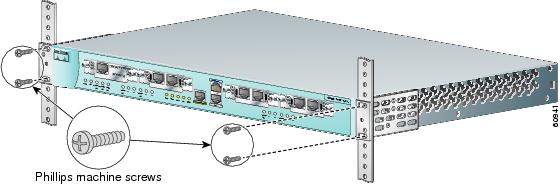
Attaching Brackets to the Rack
After the brackets are attached to the router, use the four supplied number-12 Phillips machine screws to securely attach the brackets to the rack, as shown in Figure 3.
Caution
Figure 3 Attaching Brackets to the Rack
Attaching the Optional Cable Guide
Cisco recommends attaching the cable guide to prevent the cables from obscuring the front panel of the router and the other devices installed in the rack. If the router is in a 19-inch or 24-inch rack, use the supplied black screw, as shown in Figure 4, to attach the cable guide to the left or right bracket.
Figure 4 Attaching the Cable Guide to the Router
5 Installing WIC/VIC Cards
The router has four card slots that hold Cisco WICs and VICs. Either one or two WICs may be installed, with the remaining slots holding VICs, as desired. If no WICs are present in the slots, up to four VICs may be installed. Each WIC has one or two WAN ports, and each VIC has two or more voice ports. This section describes the procedure for installing a WIC or a VIC in the router.
Note
Safety Information
This section lists safety warnings that you should be aware of before installing WICs or VICs in the router. To see translated versions of these warnings, refer to the Regulatory Compliance and Safety Information for the Cisco 1700 Routers document that came with the router.
Warning
Warning
Warning
Warning
Warning
Caution
Card Installation
Follow these steps to insert a card in the router:
Step 1
Caution
Step 2
Figure 5 Removing a WIC or VIC Slot Cover
You should be able to loosen the screws using your fingers; however, if the screws are very tight, you may need to use a Phillips screwdriver.
Step 3
Step 4
Figure 6 Inserting a WIC or VIC in the Router
Step 5
Note
Step 6
Voice Port Verification
When the router is connected to a PC and you are running the command-line interface, as described in the "Connect a PC to the Router Console Port" section, you can enter the show voice port command to identify the port numbers of voice interfaces installed in your router:
Router# show voice port slot-number/port-numberAs an example of voice port numbering, if you install VICs in both slot 1 and slot 2 of the router, the ports in each of these slots would be numbered as follows:
Slot 1—1/0 and 1/1
Slot 2—2/0 and 2/1
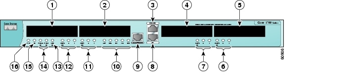
Figure 7 shows the Cisco 1760 router front panel and slot numbering.
Figure 7 Cisco 1760 Router Front Panel
6 Connecting the Router to Your Local Network
The router is connected to your local Ethernet network through the yellow 10/100 Ethernet port. You must provide the following items for this connection:
•
•
Warning
Caution
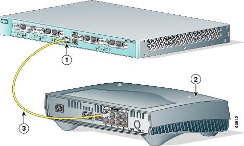
Follow these steps to connect the router to your local network:
Step 1
Figure 8 Connecting the Router to the Local Network
Step 2
7 Connect Power and Verify Installation
Read the following warnings before connecting the power to the router.
Warning
Warning
Warning
Warning
Warning
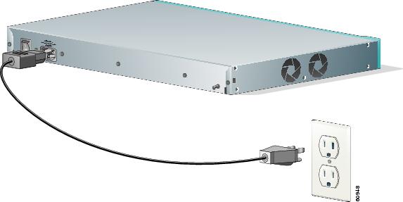
Follow these steps to connect power to the router and to turn the router on:
Step 1
Figure 9 Connecting the Power Supply
Step 2
Step 3
Step 4
•
•
•
•
•
•
8 Connect a PC to the Router Console Port
Connect a PC to the router's console port and establish a console session to view startup messages and verify voice card installation. Follow these steps to connect the router to a terminal or PC:
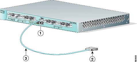
Step 1
Figure 10 Connecting the Console Cable to the Router
Step 2
Step 3
Startup messages begin to appear in your terminal emulation program window.
Caution
–
yourname con0 is now availablePress RETURN to get started.See the "Initial Configuration Using Cisco Router and Security Device Manager" section to learn how to configure your router using SDM or to learn how to obtain SDM and install it on your router.
–
--- System Configuration Dialog ---At any point you may enter a question mark '?' for help.Use ctrl-c to abort configuration dialog at any prompt.Default settings are in square brackets '[]'.Would you like to enter the initial configuration dialog? [yes/no]:To learn how to use the CLI to configure the router, see the "Initial Configuration Using Cisco CLI—Manual Configuration" section.
9 Perform Initial Configuration
You can configure your router by using one of the following tools:
•
•
Initial Configuration Using Cisco Router and Security Device Manager
If the following messages appear at the end of the startup sequence, Cisco Router and Security Device Manager (SDM) is installed on your router:
yourname con0 is now availablePress RETURN to get started.For instructions on configuring your router by using SDM, refer to the Cisco Router and Security Device Manager (SDM) Quick Start Guide that shipped with your router.
Tip
http://www.cisco.com/pcgi-bin/tablebuild.pl/sdm
To obtain the SDM quick start guide, SDM release notes, and other SDM documentation, go to www.cisco.com/go/sdm and click the Technical Documentation link.
Initial Configuration Using Cisco CLI—Manual Configuration
This section shows how to display a command-line interface (CLI) prompt for configuration using the CLI, and it directs you to documentation for the CLI configuration.
You can use the CLI if the following messages appear at the end of the startup sequence:
--- System Configuration Dialog ---At any point you may enter a question mark '?' for help.Use ctrl-c to abort configuration dialog at any prompt.Default settings are in square brackets '[]'.Would you like to enter the initial configuration dialog? [yes/no]:If these messages do not appear, SDM and a default configuration file were installed on the router at the factory. To use SDM to configure the router, see the "Initial Configuration Using Cisco Router and Security Device Manager" section.
Note
Step 1
Would you like to enter the initial configuration dialog? [yes/no]: noStep 2
Would you like to terminate autoinstall? [yes] ReturnSeveral messages appear, ending with a line similar to the following:
Copyright (c) 1986-2000 by cisco Systems, Inc.Compiled <date> <time> by <person>Step 3
...flashfs[4]: Initialization complete.Router>Step 4
Router> enableRouter#Step 5
Step 6
Verifying the Initial Configuration
To verify that the new interfaces are operating correctly, perform the following tests:
•
•
•
•
Router# show voice port slot-number/port-numberAs an example of voice port numbering, if you installed VICs in both slot 1 and slot 2 of the router, the ports in each of these slots would be numbered as follows:
Slot 1—1/0 and 1/1
Slot 2—2/0 and 2/1
When you have completed and verified the initial configuration, your Cisco router is ready to configure for specific functions. Configuring the Router Using the Cisco IOS CLI
10 Use the CLI to Configure VoIP
The following sections explain how to set up basic VoIP configurations using the Cisco IOS command line interface (CLI).
Note
•
•
•
•
•
•
•
Information for International Users
International users must set the values of certain voice-port commands, such as cptone, that are specific to their country. Refer to the Cisco 1751 Router Software Configuration Guide, available on Cisco.com, for details.
The rest of this guide explains how to configure your router for VoIP traffic.
Saving the Configuration
You must save the new configuration to nonvolatile RAM (NVRAM) periodically during the configuration process and also when you finish configuring the router.
Cisco IOS software uses two configuration files—startup-config and running-config. The startup-config file is a backup file that has all the information you specified about the router interfaces. The startup-config file is used by the router on the next restart. The running-config file has the current operating configuration with the changes you have just made. You can make any changes to the running-config file; however, these changes will be lost when the router powers down. To make these changes permanent, copy the running-config file to the startup-config file stored in NVRAM.
Follow these steps for each router to write the new configuration to NVRAM:
Step 1
Step 2
Router# show startup-configStep 3
Router# show running-configStep 4
Router# copy running-config startup-configBuilding configuration. . .[OK]Router#The router is now configured to start in the new configuration.
Configuring the Fast Ethernet Interface
To configure the Fast Ethernet interface, follow these steps, beginning in global configuration mode:
Configuring a Dial Plan
Use a dial plan to map the destination telephone numbers with the voice ports on the router. In North America, the North American Numbering Plan (NANP) is used, which consists of an area code, an office code, and a station code. Area codes are assigned geographically, office codes are assigned to specific switches, and station codes identify specific ports on each switch. The format in North America is 1Nxx-Nxx-xxxx, with N = digits 2 through 9 and x = digits 0 through 9. Internationally, each country is assigned a one- to three-digit country code; the country's dialing plan follows the country code.
In corporate environments, VoIP can be configured to recognize extension numbers and expand them into their full E.164 (international public telecommunications numbering plan) dialed numbers by using two commands in tandem: destination-pattern and num-exp. Before you configure these two commands, map individual telephone extensions with their full E.164 dialed numbers. You can do this easily by creating a number expansion table.
For Cisco voice implementations, three types of dial peers are used to match a dialed number to either a local telephony port or a remote IP address:
•
Router(config)# dial-peer voice 401 potsRouter(config-dial-peer)# destination-pattern 14085553737Router(config-dial-peer)# port 0/0The destination-pattern command defines the telephone number associated with the POTS dial peer. The port command associates the POTS dial peer with a specific logical dial interface, normally the voice port connecting your router to the local POTS network.
•
Router(config)# dial-peer voice 501 voipRouter(config-dial-peer)# destination-pattern 1919555....Router(config-dial-peer)# session target ipv4:192.168.11.3The destination-pattern command defines the telephone number associated with the VoIP dial peer. The session target command specifies a destination IP address for the VoIP dial peer.
•
Router(config)# dial-peer voice 601 vofrRouter(config-dial-peer)# destination-pattern 14087677448Router(config-dial-peer)# session target serial 0/0 100The destination-pattern command defines the telephone number associated with the VoFR dial peer. The session target command specifies a destination DLCI for the VoFR dial peer.
Use the dial-peer voice command to define dial peers and to change to dial peer configuration mode. For examples, see the "Configuring FXS Interfaces" section, the "Configuring FXO Interfaces" section, and the "Configuring E&M Interfaces" section.
Wildcards and Number Expansion
Office PBXs are configured so that a user can dial a local call (within the same PBX) by dialing the extension only—for instance, the four-digit extension 3737, or the five-digit extension 53737—rather than dialing the full telephone number, 1 408 555-3737.
You can provide the same shortcut on a VoIP network by using the number-expansion (num-exp) command.
Router(config)# num-exp 5.... 1408555....This command tells the router to expand a particular sequence of dialed numbers into a complete telephone number (destination pattern) as shown in Table 1.
You can use a period (.) as a wildcard character representing a single digit in a telephone number.
You can use the show num-exp command to verify the number expansion information.
Router# show num-exp [dialed-number]After you have configured dial peers and assigned destination patterns to them, you can use the show dialplan number command to see how a telephone number maps to a dial peer.
Router# show dialplan number [dialed-number]
Note
Configuring Voice Interface Cards
The router supports one to four Cisco VICs. Each VIC provides two ports. You need one VIC port for each voice connection.
Note
There are five types of VIC interfaces:
•
•
•
•
•
Figure 11 shows a typical VIC.
Figure 11 Voice Interface Card
You should install and cable the VICs before you perform the software configuration tasks that follow.
Configuring FXS Interfaces
This section explains how to configure ports on FXS VICs that connect directly to a standard telephone, a fax machine, or a similar device.
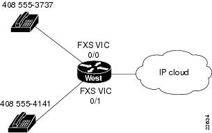
Figure 12 shows a basic voice network. A small business uses a Cisco 1760 router (named West) to provide telephone and fax connections among employees in its office. Two of these telephones are connected to an FXS VIC port in the West router.
Figure 12 Basic Voice Network (West Router)
Note
(For information about port numbering, see the "Voice Port Verification" section.)
Table 2 West Router Telephone Numbers and Voice Ports
408 555-3737
0/0
408 555-4141
0/1
Note
Local Dial Peers
To route a received voice call to the right destination, the router needs to know which telephone number belongs to each voice port. For instance, if a call comes in for 408 555-3737, the router needs to know that this telephone is connected to voice port 0/0 (as shown in Figure 12). In other words, the router needs to know the information in Table 2.
To hold this information, Cisco IOS software uses objects called dial peers. A telephone number, a voice port, and other call parameters are tied together by associating them all with the same dial peer. Configuring dial peers is similar to configuring static IP routes—you are telling the router what path to follow to route the call. All voice technologies use dial peers to define the characteristics associated with a call leg. A call leg is a segment of a call path, for instance, between a telephone and a router, a router and a network, a router and a PBX, or a router and the PSTN. Each call leg corresponds to a dial peer.
Dial peers are identified by numbers, but they are usually referred to as tags to avoid confusion with telephone numbers. Dial-peer tags are arbitrary integers that can range from 1 to 231 - 1 (2147483647). Within the allowed range, you can choose any dial-peer tag that is convenient or that makes sense to you. Dial peers on the same router must have unique tags, but you can reuse the tags on other routers.
Table 3 assigns a dial-peer tag to each telephone number and its associated voice port on the West router. This type of dial peer is called a POTS dial peer or a local dial peer. The term POTS (plain old telephone service) means that the dial peer associates a physical voice port with a local telephone device. (Voice over IP, or VoIP, dial peers are explained in the "Calling Between Routers" section.)
Table 3 West Router Local Dial Peers
408 555-3737
0/0
401
408 555-4141
0/1
402
You should construct a table similar to Table 3 for your own routers, assigning your own telephone numbers and dial-peer tags.
Note
To configure the router with the dial-peer information in Table 3, enter the following global configuration commands:
West> enablePassword:West# configure terminalWest(config)# dial-peer voice 401 potsWest(config-dial-peer)# destination-pattern 14085553737West(config-dial-peer)# port 0/0West(config)# dial-peer voice 402 potsWest(config-dial-peer)# destination-pattern 14085554141West(config-dial-peer)# port 0/1West(config-dial-peer)# exitWest(config)#These commands are summarized in Figure 13.
Figure 13 West Router Configured for Local Dial Peers
The dial-peer command always takes the argument voice. The number following it is the dial-peer tag, and pots is the type of dial peer.
Cisco IOS software refers to a telephone number as a destination pattern because it is the destination for an incoming or outgoing call. Enter these numbers with the destination-pattern command. A destination pattern can include asterisks (*) and pound signs (#) from the telephone keypad, and commas (,) and periods (.), which have special meanings. Parentheses ( () ), hyphens (-), slashes (/), and spaces ( ), which are often used to make telephone numbers easier for humans to read, are not allowed.
Notice that the commands in the examples puts the prefix 1 (used in the United States to indicate a long-distance number) and an area code in front of the remaining numbers to complete the destination pattern. You need to include similar codes for your country if the VoIP equipment needs to establish a connection to the Public Switched Telephone Network (PSTN).
Note
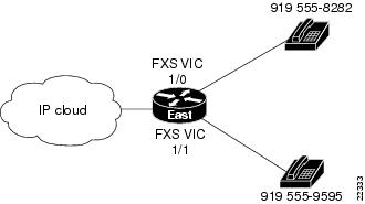
The business that owns the West router also has a branch office, called East. Figure 14 shows the East office network, and Table 4 lists the phone numbers, voice ports, and dial-peer tags for this office.
Figure 14 Basic Voice Network (East Router)
Table 4 East Router Local Dial Peers
919 555-8282
19195558282
1/0
901
919 555-9595
19195559595
1/1
902
Enter the following commands to configure the local ports on the East router with the dial-peer information in Table 4:
East(config)# dial-peer voice 901 potsEast(config-dial-peer)# destination-pattern 19195558282East(config-dial-peer)# port 1/0East(config)# dial-peer voice 902 potsEast(config-dial-peer)# destination-pattern 19195559595East(config-dial-peer)# port 1/1East(config-dial-peer)# exitEast(config)#These commands are summarized in Figure 15.
Figure 15 East Router Configured for Local Dial Peers
Checking the Local Dial Peer Configuration
If you configured POTS dial peers on your router by following these examples, you can place calls between telephones connected to the same router. You can also use the show dial-peer voice command to verify that the data that you configured is correct.
Note
Calling Between Routers
To enable the West and East offices to send voice traffic to each other over the same IP network they use for data traffic, use a WIC on each router to provide a connection to the IP network, as shown in Figure 16.
Figure 16 IP Connection Between Routers
Look at the connection between the West router and the IP network. This connection does not include a voice port or an attached telephone—it leads from a WAN interface to a remote destination somewhere on the IP network. IP routers can locate IP addresses on the network, but they cannot locate telephone numbers. To route an outgoing voice call over this connection, the West router must associate a telephone number in the East office with the IP address of the East router.
Table 5 assigns a dial-peer tag to each telephone number and its associated IP address on the West router. This type of dial peer is called a remote dial peer or VoIP dial peer. (Remember, the dial-peer tags are arbitrary.) A VoIP dial peer associates a telephone number with an IP address.
You can create a VoIP dial peer on the West router for every telephone on the East router, all associated with the same IP address. But it is much easier to use periods as wildcards, as shown in Table 6.
Table 6 West Router Remote Dial Peers with Wildcards
East
919 555-xxxx
1919555....
192.168.11.3
501
Construct a table similar to Table 6 for your own routers, assigning your own telephone numbers, IP addresses, and dial-peer tags.
Note
Enter the following information on the West router to create the dial-peer configuration given in Table 6:
West(config)# dial-peer voice 501 voipWest(config-dial-peer)# destination-pattern 1919555....West(config-dial-peer)# session target ipv4:192.168.11.3Cisco IOS software describes the remote network as the session target. This command is followed by the IP address of the remote router. The prefix ipv4 means IP version 4. Alternatively, you can use the prefix dns followed by the Domain Name System (DNS) name, as follows:
West(config-dial-peer)# session target dns:voice.eastrouter.comConfigure a dial peer on each router for each telephone number on every other router connected to it.
You can simplify this process by configuring number expansion for East router telephone numbers on the West router:
West(config)# num-exp 5.... 1919555....Now users can dial a five-digit extension beginning with 5 from a telephone on the West router to reach a telephone on the East router.
These commands are summarized in Figure 17.
Figure 17 West Router Configured for Remote Dial Peers
The West router is now configured to send calls to the East router.
Table 7 shows how to configure the East router to send calls to the West router.
Table 7 East Router Remote Dial Peers with Wildcards
West
408 555-xxxx
192.168.19.27
801
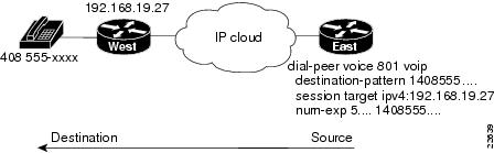
Enter the following information on the East router to create the dial-peer configuration given in Table 7:
East(config)# num-exp 5.... 1408555....East(config)# dial-peer voice 801 voipEast(config-dial-peer)# destination-pattern 1408555....East(config-dial-peer)# session target ipv4:192.168.19.27These commands are summarized in Figure 18.
Figure 18 East Router Configured for Remote Dial Peers
Other Routers on the Network
If the path between the endpoints of a voice call travels through intermediate routers, configure those routers for VoIP traffic, as described in the "Configuring FXS Interfaces" section.
You need to configure POTS or VoIP dial peers on an intermediate router only if that router also has voice devices attached to it.
Checking the Remote Dial Peer Configuration
If you configured VoIP dial peers on your router by following these examples, you can place calls from that router to telephones on the remote routers (using just the extension if you configured number expansion). If you have trouble placing calls, ping the remote router to make sure you have IP connectivity, or use the show dial-peer voice command to verify that the data you configured is correct.
Note
Configuring FXO Interfaces
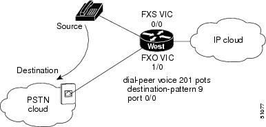
FXO interfaces provide a gateway from the VoIP network to the analog PSTN or to a PBX that does not support E&M signaling so that users can reach telephones and fax machines outside the VoIP network. Figure 19 shows a typical FXO gateway attached to the West router.
Figure 19 FXO Gateway to PSTN
To create a POTS dial peer for an FXS interface as explained earlier, you enter the complete telephone number of the attached telephone as the destination pattern for incoming calls. However, to create a POTS dial peer for an FXO interface, the destination pattern refers to outgoing calls, and you can include wildcards in it because the PSTN performs the switching.
The VoIP feature can also remove digits that you do not want to send to the PSTN. For instance, to dial 9 to reach an outside line (that is, the analog PSTN), enter the following commands:
West> enablePassword:West# configure terminalWest(config)# dial-peer voice 201 potsWest(config-dial-peer)# destination-pattern 9West(config-dial-peer)# port 1/0When you dial 9, the router makes a connection to the PSTN through voice port 1/0. The PSTN then provides a dial tone. Any digits you enter on the telephone thereafter are interpreted on the PSTN.
To enable East router users to make calls over the West router local PSTN, enter the following commands:
East(config)# dial-peer voice 701 voipEast(config-dial-peer)# destination-pattern 7East(config-dial-peer)# session target ipv4:192.168.19.27West(config)# dial-peer voice 601 potsWest(config-dial-peer)# destination-pattern 7West(config-dial-peer)# port 1/0When you dial 7 on the East router, the call is connected to the PSTN on the West router. The PSTN then provides a dial tone, and any digits you enter on the telephone thereafter are interpreted on the PSTN.
Note
Checking the FXO Configuration
If you configured your FXO interface according to the example described in the "Configuring FXO Interfaces" section, you can place outgoing calls over the PSTN. If you have trouble placing calls, use the show voice port command to make sure that the VIC is installed correctly. Use the show dial-peer voice command to make sure that the data you configured is correct, and test the PSTN by connecting a handset directly to the PSTN outlet and placing a call.
Note
Configuring E&M Interfaces
If you have more than a few voice users at each location, the cost of voice ports and routers and the effort needed to configure dial peers for all the combinations of origins and destinations increases rapidly. In this situation, it might be more efficient to use a PBX at each location to switch local traffic and direct incoming calls and then use E&M VICs to connect the PBXs over an IP network.
Figure 20 shows a company with two offices, West and East. Each office has a PBX to operate its internal telephone network, and the IP network carries voice traffic between the offices. Each PBX connects to an E&M VIC port in the router.
Figure 20 Linking PBXs over the IP Network (Local Dial Peers)
To configure E&M voice ports, use the following commands beginning in privileged EXEC mode.
Both PBXs in the example shown in Figure 20 use E&M interface Type 2, with four-wire operation and immediate-start signaling. The values for your configuration depend on your PBX and are available from your telecommunications department or the PBX manufacturer. For more information about E&M interface configuration commands, refer to the "VoIP Commands" chapter of the Cisco 1751 Router Software Configuration Guide.
In this example, West users can dial 5 and a four-digit extension to reach telephones in the East office. East users can dial 5 and a four-digit extension to reach telephones in the West office.
The West router connects to the PBX through an E&M VIC port 0/0. This port is associated with a POTS dial peer for incoming calls. But you no longer need to associate every telephone number with its own port. Instead, you can configure a local dial peer as if all the West telephones (represented by a wildcard destination pattern) are connected directly to this port, as shown in the following commands:
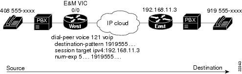
West> enablePassword:West# configure terminalWest(config)# dial-peer voice 111 potsWest(config-dial-peer)# destination-pattern 1408555....West(config-dial-peer)# port 0/0Configure VoIP dial peers for outgoing calls and associate destination phone numbers on the East router with that router IP address, as shown in Figure 21, and in the following commands:
West(config)# dial-peer voice 121 voipWest(config-dial-peer)# destination-pattern 1919555....West(config-dial-peer)# session target ipv4:192.168.11.3West(config-dial-peer)# exitWest(config)#Figure 21 Linking PBXs over the IP Network (Remote Dial Peers)
Now configure number expansion so that numbers beginning with 5 (belonging to the East office) and sent by the West PBX to the West router are expanded into the full destination pattern:
West(config)# num-exp 5.... 1919555....
Note
Finally, enter the following global configuration voice-port command to configure the E&M port:
West(config)# voice-port 0/0West(config-voice-port)# signal immediateWest(config-voice-port)# operation 4-wireWest(config-voice-port)# type 2West(config-voice-port)# shutWest(config-voice-port)# no shut
Note
Note
Configure the East router similar to the West router. The East router connects to the PBX through an E&M VIC port 0/1. Enter the following commands to configure a POTS dial peer for all East telephones:
East(config)# dial-peer voice 211 potsEast(config-dial-peer)# destination-pattern 1919555....East(config-dial-peer)# port 0/1Enter the following commands to configure a VoIP dial peer for telephones on the West router:
East(config)# dial-peer voice 221 voipEast(config-dial-peer)# destination-pattern 1408555....East(config-dial-peer)# session target ipv4:192.168.19.27East(config-dial-peer)# exitEast(config)#Enter the following command to configure number expansion and to make it easy for East users to dial numbers on the West router:
West(config)# num-exp 5.... 1408555....Finally, configure the E&M port:
East(config)# voice-port 0/1East(config-voice-port)# signal immediateEast(config-voice-port)# operation 4-wireEast(config-voice-port)# type 2East(config-voice-port)# shutEast(config-voice-port)# no shutChecking the E&M Configuration
If you configured the E&M interfaces correctly, you can place calls from a telephone served by one PBX to a telephone served by the other PBX (using just the extension, if you configured number expansion). If you have trouble placing calls, ping the remote router to make sure you have IP connectivity.
Note
Configuring ISDN BRI NT/TE Interfaces
The ISDN BRI VIC provides digital connectivity for VoIP networks using the European Telecommunications Standards Institute (ETSI) Net3 switch type. The BRI VIC presents an ISDN S/T physical interface that connects to a network termination (NT) or terminal equipment (TE) device. With the ISDN BRI VIC, you can connect the Cisco 1760 router to a PBX network in NT or TE mode, or to a PSTN in TE mode.
Each of the two BRI ports can operate in NT mode as the clock source or in TE mode as a clock slave. For example:
•
•
Figure 22 shows an example of a network using ISDN BRI voice interfaces.
Figure 22 A Network Using ISDN BRI Voice Interfaces
Configuring the BRI Layer 1
At the BRI Layer 1, you can configure each port of the VIC to operate in NT (clock source) or TE (clock slave) mode by using the IOS isdn layer1-emulate command in interface configuration mode:
isdn layer1-emulate {network | user}
where network enables the VIC to operate in the NT mode, and user enables it to operate in the TE mode. The default setting for each port is the TE mode.
Configuring the ISDN Protocol
Depending on your ISDN switch type, the Layer 2 protocol may be configured to operate in NT or TE mode. To do this, use the isdn protocol-emulate command in interface configuration mode:
isdn protocol-emulate {network | user}
where network enables the ISDN Layer 2 to operate in the NT mode, and user enables it to operate in the TE mode. The default setting is the TE mode.
Note
Turning the Line Power On/Off
To control the line power (phantom power only) being supplied to a connected device, use the line_power command in interface configuration mode:
line_power
no line_power
The line_power and no line_power commands are valid only for a BRI port operating in NT mode. If a port is equipped with hardware to supply line power, using these commands will activate or deactivate line power provision from that port.
Setting the Network Clock Priority
If a port is operating in TE mode, you can set the clock priority for that port. The clock priority determines whether the external clock on the ISDN line or the internal clock on the system board takes control. To change the clock priority, use the network-clock-priority command in interface configuration mode:
network-clock-priority {high | low}
where high enables the external clock, and low enables the internal clock to drive the VIC. By default, the clock priority is set to high.
Note
Configuration Example
To configure each BRI interface, follow these steps, starting in privileged user mode.
Note
Debugging Commands
Use the following commands to debug your configuration:
•
•
•
•
•
•
•
For more information about these commands, see the IOS documentation.
Configuring DID Interfaces
Direct Inward Dialing (DID) enables external callers to direct-dial an internal extension on your PBX, without operator assistance. This service makes use of DID trunks provided by the local central office (CO), which forward only the last three to five digits of a phone number to your PBX. If, for example, a company has a PBX with extensions 555-1000 through 555-1999, and an external caller dials 555-1234, the local CO forwards 234 to the PBX. The PBX then rings extension 234.
When this feature is configured, a voice-enabled Cisco router can receive calls from a DID trunk and connect them to the appropriate extensions.
The DID feature makes it seem that all extensions on a PBX have direct lines to the PSTN. This is accomplished without the expense associated with connecting each extension to the PSTN. Besides saving the cost of an operator, DID lets callers feel that they are calling specific individuals, rather than calling a large company.
Figure 23 shows a hypothetical topology in which a user connected to the PSTN (User A) dials various numbers; this user is then connected to the appropriate extensions on a PBX.
Figure 23 DID Support for Cisco 1760 Routers
Prerequisites
The following actions are required to support DID:
•
•
•
•
•
•
Configuring a Voice Port to Support DID
Use the signal did command, with the appropriate signal type, to configure a DID voice port:
West(config-voice-port)# signal did{wink-start | immediate | delay-dial}where wink-start, immediate, and delay-dial indicate the signal types. The default signal type is immediate.
As an example, the port can be configured as shown in the following commands:
Router# configure terminalRouter(config)# voice-port 1/0West(config-voice-port)# signal did wink-startVerifying DID Voice Port Configuration
To verify voice-port configuration, enter the show voice port command. You can specify a voice port or view the status of all configured voice ports. In the following example, the specified port is configured for DID.
Router# show voice port 1/0Foreign Exchange Station with Direct Inward Dialing (FXS-DID) 1/0 Slot is 1, Port is 0Type of VoicePort is DID-INOperation State is DORMANTAdministrative State is UPNo Interface Down FailureDescription is not setNoise Regeneration is enabledNon Linear Processing is enabledMusic On Hold Threshold is Set to -38 dBmIn Gain is Set to 0 dBOut Attenuation is Set to 0 dBEcho Cancellation is enabledEcho Cancel Coverage is set to 8 msPlayout-delay Mode is set to defaultPlayout-delay Nominal is set to 60 msPlayout-delay Maximum is set to 200 msPlayout-delay Minimum mode is set to default, value 4 msPlayout-delay Fax is set to 300 msConnection Mode is normalConnection Number is not setInitial Time Out is set to 10 sInterdigit Time Out is set to 10 sCall Disconnect Time Out is set to 3 sRinging Time Out is set to 180 sWait Release Time Out is set to 3 sCompanding Type is u-lawRegion Tone is set for USAnalog Info Follows:Currently processing noneMaintenance Mode Set to None (not in mtc mode)Number of signaling protocol errors are 0Impedance is set to 600r OhmStation name Chalil Mohanan, Station number 1234567Voice card specific Info Follows:Signal Type is wink-startDial Type is dtmfIn Seizure is inactiveOut Seizure is inactiveDigit Duration Timing is set to 100 msInterDigit Duration Timing is set to 100 msPulse Rate Timing is set to 10 pulses/secondInterDigit Pulse Duration Timing is set to 750 msClear Wait Duration Timing is set to 400 msWink Wait Duration Timing is set to 200 msWait Wink Duration Timing is set to 550 msWink Duration Timing is set to 200 msDelay Start Timing is set to 300 msDelay Duration Timing is set to 2000 msDial Pulse Min. Delay is set to 140 msPercent Break of Pulse is 60 percentAuto Cut-through is disabledDialout Delay for immediate start is 300 msConfiguring Quality of Service
The sections that follow provide an overview and brief explanations of Quality of Service (QoS) mechanisms. To ensure the best QoS, you will need to configure various QoS mechanisms together. The examples in the following sections are given only to illustrate various QoS concepts. To configure your router, please use the guidelines, commands and example configurations that are given in the Cisco IOS Quality of Service Solutions Configuration Guide, Release 12.2 or later.
Voice traffic is much more sensitive to timing variations than data traffic. For good voice performance, you need to configure your data network so that voice packets are not lost or delayed. To achieve the level of network performance needed for VoIP connections, use the following features to improve QoS:
•
•
•
Cisco IOS software provides many other tools for ensuring QoS, such as custom queuing, priority queuing, and weighted fair queuing. For further information and more detailed examples of QoS configuration, refer to the "Congestion Management" chapter in the Cisco IOS Quality of Service Solutions Configuration Guide, Release 12.2 or later.
Note
Configuring VoIP on a Frame Relay link involves special considerations. See the "Frame Relay Configuration for VoIP" section.
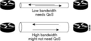
On a relatively low-bandwidth connection, such as a PPP or High-Level Data Link Control (HDLC) serial link, you should consider using methods to ensure QoS. If you have a high-bandwidth network, such as Ethernet or Fast Ethernet, and voice and data traffic together occupy only a small fraction of the bandwidth available, you might not need to provide QoS mechanisms. (See Figure 24.)
Figure 24 Bandwidth Versus Quality of Service
IP Precedence
Use the ip precedence command to give voice packets a higher priority than other IP data traffic. Every IP packet is given a precedence level: the numbers 1 through 5 identify classes for IP flows; the numbers 6 through 7 are used for network and backbone routing and updates. You can configure voice packets for higher priority by setting the IP precedence value to 5. Internal routers using weighted fair queuing give these packets priority. This command applies only to VoIP dial peers. The following example sets the IP precedence to 5:
Router> enablePassword:Router# configure terminalRouter(config)# dial-peer voice 221 voipRouter(config-dial-peer)# ip precedence 5Use the ip precedence command if RSVP is not enabled and if you would like to give voice packets a higher priority than other IP data traffic.
Low Latency Queuing
Low latency queuing (LLQ) provides a low-latency, strict-priority transmit queue for real-time traffic, such as VoIP traffic. Strict-priority queuing allows delay-sensitive data such as voice to be dequeued and sent first (before packets in other queues are dequeued), giving delay-sensitive data preferential treatment over other traffic. This reduces jitter in voice conversations.
Configuring LLQ
Ensure that the voice and data packets have different IP precedence values. This will allow the router to differentiate between them. Normally, data packets should have an IP precedence of 0, while voice packets should have an IP precedence of 5. If the VoIP packets are generated from within the router, you may set IP precedence to 5 for these packets by using the procedure in the "IP Precedence" section.
Create an access list and a class map for the voice packets.
Router(config)# access-list 101 permit ip any any precedence 5Router(config)# class-map match-all voiceLink the class map to the access list.
Router(config-cmap)# match access-group 101Configure LLQ for voice traffic by creating a policy map and defining its class.
Router(config)# policymap mypolicyRouter(config-pmap)# class voiceAssign priority bandwidth to the voice traffic. The priority bandwidth assigned (in kilobits per second) depends on the codec used and the number of simultaneous calls allowed.
Router(config-pmap-c)# priority 200Attach LLQ to the dialer interface, and create a service policy.
Router(config)# interface dialer 1Router(config-if)# service-policy out mypolicyMultilink PPP with Link Fragmentation Interleave
Multilink PPP with link fragmentation interleave (MLPPP with LFI) allows large packets to be multilink-encapsulated and fragmented into smaller packets, thus ensuring that voice packets are transmitted without delay; small real-time packets, which are not multilink-encapsulated, are transmitted between fragments of the large packets. The interleaving feature also provides a special transmit queue for the smaller, delay-sensitive packets, enabling them to be transmitted earlier than other flows.
You should configure MLPPP with LFI if you have a dialer, an ISDN PRI or BRI interface, or a virtual template, and either of the following:
•
•
Note
Configuring MLPPP with LFI
To configure MLPPP with LFI on a dialer, ISDN PRI or ISDN BRI interface, or a virtual template, you must first configure MLPPP with LFI on the interface or template by entering the following commands while in interface configuration mode:
Router(config-if)# encapsulation pppRouter(config-if)# ppp multilinkRouter(config-if)# ppp multilink interleaveOptionally, configure a maximum fragment delay:
Router(config-if)# ppp multilink fragment-delay millisecondsYou can also reserve a special queue for real-time packet flows to specified destination User Datagram Protocol (UDP) ports, allowing real-time traffic to have higher priority than other flows. You need the following command only if you have not configured RSVP:
Router(config-if)# ip rtp reserve lowest-UDP-port range-of-portsFor virtual templates only, apply the virtual template to the multilink bundle:
Router(config-if)# multilink virtual-template 1To create a virtual template interface, enter the following interface virtual-template global configuration command:
Router(config)# interface virtual-template 1Real-Time Transport Protocol Header Compression
Real-Time Transport Protocol (RTP) header compression on a PPP, HDLC, or similar serial interface compresses the packet header to reduce network overhead.
You should configure RTP header compression on a serial interface if you have either of the following:
•
•
Note
Configuring RTP Header Compression
Enable RTP header compression at both ends of the serial link by entering the ip rtp header-compression interface configuration command:
Router(config-if)# ip rtp header-compression
Note
Frame Relay Configuration for VoIP
Configuring VoIP on a Frame Relay link involves certain special considerations to ensure acceptable voice quality. For Frame Relay links with slow output rates (64 kbps or less) and with data and voice being transmitted over the same permanent virtual circuit (PVC), you should configure the following parameters:
•
The following example configures an MTU size of 300 bytes over serial interface 0/0:
Router# interface serial 0/0Router(config-if)# mtu 300
Note
•
The following example configures RSVP over serial subinterface 0/0.1:
Router(config-if)# interface serial 0/0.1 point-to-pointRouter(config-if)# ip address 192.168.19.0 255.0.0.0Router(config-if)# ip rsvp bandwidth 48 48•
The following command configures RTP header compression on the selected subinterface:
Router(config-if)# frame-relay ip rtp header-compression•
The following command configures generic traffic shaping with a CIR of 32000 bps:
Router(config-if)# traffic-shape rate 32000For further information and more detailed examples of Frame Relay configuration, refer to the Cisco 1751 Router Voice-over-IP Configuration Guide.
11 Obtaining Documentation
Cisco documentation and additional literature are available on Cisco.com. Cisco also provides several ways to obtain technical assistance and other technical resources. These sections explain how to obtain technical information from Cisco Systems.
Cisco.com
You can access the most current Cisco documentation at this URL:
http://www.cisco.com/univercd/home/home.htm
You can access the Cisco website at this URL:
You can access international Cisco websites at this URL:
http://www.cisco.com/public/countries_languages.shtml
Documentation DVD
Cisco documentation and additional literature are available in a Documentation DVD package, which may have shipped with your product. The Documentation DVD is updated regularly and may be more current than printed documentation. The Documentation DVD package is available as a single unit.
Registered Cisco.com users (Cisco direct customers) can order a Cisco Documentation DVD (product number DOC-DOCDVD=) from the Ordering tool or Cisco Marketplace.
Cisco Ordering tool:
http://www.cisco.com/en/US/partner/ordering/
Cisco Marketplace:
http://www.cisco.com/go/marketplace/
Ordering Documentation
You can find instructions for ordering documentation at this URL:
http://www.cisco.com/univercd/cc/td/doc/es_inpck/pdi.htm
You can order Cisco documentation in these ways:
•
http://www.cisco.com/en/US/partner/ordering/
•
12 Documentation Feedback
You can send comments about technical documentation to bug-doc@cisco.com.
You can submit comments by using the response card (if present) behind the front cover of your document or by writing to the following address:
Cisco Systems
Attn: Customer Document Ordering
170 West Tasman Drive
San Jose, CA 95134-9883We appreciate your comments.
13 Cisco Product Security Overview
Cisco provides a free online Security Vulnerability Policy portal at this URL:
http://www.cisco.com/en/US/products/products_security_vulnerability_policy.html
From this site, you can perform these tasks:
•
•
•
A current list of security advisories and notices for Cisco products is available at this URL:
If you prefer to see advisories and notices as they are updated in real time, you can access a Product Security Incident Response Team Really Simple Syndication (PSIRT RSS) feed from this URL:
http://www.cisco.com/en/US/products/products_psirt_rss_feed.html
Reporting Security Problems in Cisco Products
Cisco is committed to delivering secure products. We test our products internally before we release them, and we strive to correct all vulnerabilities quickly. If you think that you might have identified a vulnerability in a Cisco product, contact PSIRT:
•
•
Tip
Never use a revoked or an expired encryption key. The correct public key to use in your correspondence with PSIRT is the one that has the most recent creation date in this public key server list:
http://pgp.mit.edu:11371/pks/lookup?search=psirt%40cisco.com&op=index&exact=on
In an emergency, you can also reach PSIRT by telephone:
•
•
14 Obtaining Technical Assistance
For all customers, partners, resellers, and distributors who hold valid Cisco service contracts, Cisco Technical Support provides 24-hour-a-day, award-winning technical assistance. The Cisco Technical Support Website on Cisco.com features extensive online support resources. In addition, Cisco Technical Assistance Center (TAC) engineers provide telephone support. If you do not hold a valid Cisco service contract, contact your reseller.
Cisco Technical Support Website
The Cisco Technical Support Website provides online documents and tools for troubleshooting and resolving technical issues with Cisco products and technologies. The website is available 24 hours a day, 365 days a year, at this URL:
http://www.cisco.com/techsupport
Access to all tools on the Cisco Technical Support Website requires a Cisco.com user ID and password. If you have a valid service contract but do not have a user ID or password, you can register at this URL:
http://tools.cisco.com/RPF/register/register.do
Note
Submitting a Service Request
Using the online TAC Service Request Tool is the fastest way to open S3 and S4 service requests. (S3 and S4 service requests are those in which your network is minimally impaired or for which you require product information.) After you describe your situation, the TAC Service Request Tool provides recommended solutions. If your issue is not resolved using the recommended resources, your service request is assigned to a Cisco TAC engineer. The TAC Service Request Tool is located at this URL:
http://www.cisco.com/techsupport/servicerequest
For S1 or S2 service requests or if you do not have Internet access, contact the Cisco TAC by telephone. (S1 or S2 service requests are those in which your production network is down or severely degraded.) Cisco TAC engineers are assigned immediately to S1 and S2 service requests to help keep your business operations running smoothly.
To open a service request by telephone, use one of the following numbers:
Asia-Pacific: +61 2 8446 7411 (Australia: 1 800 805 227)
EMEA: +32 2 704 55 55
USA: 1 800 553-2447For a complete list of Cisco TAC contacts, go to this URL:
http://www.cisco.com/techsupport/contacts
Definitions of Service Request Severity
To ensure that all service requests are reported in a standard format, Cisco has established severity definitions.
Severity 1 (S1)—Your network is "down," or there is a critical impact to your business operations. You and Cisco will commit all necessary resources around the clock to resolve the situation.
Severity 2 (S2)—Operation of an existing network is severely degraded, or significant aspects of your business operation are negatively affected by inadequate performance of Cisco products. You and Cisco will commit full-time resources during normal business hours to resolve the situation.
Severity 3 (S3)—Operational performance of your network is impaired, but most business operations remain functional. You and Cisco will commit resources during normal business hours to restore service to satisfactory levels.
Severity 4 (S4)—You require information or assistance with Cisco product capabilities, installation, or configuration. There is little or no effect on your business operations.
15 Obtaining Additional Publications and Information
Information about Cisco products, technologies, and network solutions is available from various online and printed sources.
•
http://www.cisco.com/go/marketplace/
•
•
•
http://www.cisco.com/go/iqmagazine
•
•