Feedback Feedback
|
Table Of Contents
Nonredundant and Redundant System Configurations
Preventing Electrostatic Discharge Damage
Removing and Installing a CSC or an SFC
Verifying the Installation of the Clock and Scheduler Card
Removing and Installing an SFC
Verifying the Installation of the SFC
Removing and Installing an Alarm Card
Verifying the Installation of the Alarm Card
Troubleshooting the Switch Fabric
Grant Parity and Request Errors
Properly Seating Switch Fabric Cards
Regulatory, Compliance, and Safety Information
Translated Safety Warnings and Agency Approvals
Electromagnetic Compatibility Regulatory Statements
Class A Notice for Taiwan and Other Traditional Chinese Markets
Cisco 12006 and Cisco 12406 Router Clock and Scheduler, Switch Fabric, and Alarm Card Replacement Instructions
Document Order Number: DOC-78-16106-01, May 30, 2008
Product Numbers: GSR6-CSC=, MAS-GSR6-CSCBLNK=, GSR6-SFC=, GSR6-ALRM=, 12006-CSC=, 12006-SFC=
This publication provides instructions for removing and installing a clock and scheduler card (CSC), switch fabric card (SFC), and alarm card on Cisco 12006 and Cisco 12406 Routers. The CSC and SFC are a card set referred to as the switch fabric. The alarm card is not a part of the switch fabric set.
In addition, instructions for verifying the operation of the system after you replace a card along with switch fabric troubleshooting information are also included.
These two router models are differentiated by the switching capacity of the switch fabric installed in the router:
•
Cisco 12006 Router—2.5-Gbps switch fabric
•
Other than the switch fabric, these routers are identical in most respects. Any differences between the models are described in the appropriate locations. Unless otherwise noted, all information in this publication applies to both router models.
Contents
•
•
•
•
•
Switch Fabric Overview
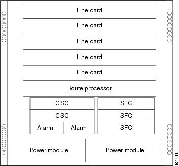
The default switch fabric configuration for the Cisco 12006 or Cisco 12406 Router is one CSC and three SFCs. If 2N redundancy is needed, a second CSC can be added to the chassis. The CSC and SFC card slots are located under the route processor (RP) and line card cage. Figure 1 shows the location of these card slots in the chassis.
Figure 1 Cisco 12006 and Cisco 12406 Router Chassis Card Slot Locations
The CSCs occupy the half-width slots on the lower left side of the chassis, directly under the RP and line card cage. The three SFCs occupy the three half-width slots on the lower right side of the chassis. The alarm cards occupy the two narrow slots directly under the CSC slots.
Switch Fabric Types
The Cisco 12006 Router is based on a 2.5-Gbps switch fabric, where each SFC or CSC provides a 2.5-Gbps full-duplex connection to each line card in the system. The 2.5-Gbps switch fabric consists of the 12006 Advanced Clock and Scheduler Card (product number 12006-CSC=) and the 12006 Advanced Switch Fabric Card (product number 12006-SFC=). The 2.5-Gbps switch fabric can be identified by the identification labels on the cards: The CSC is labeled CSC-30/120; the SFC is labeled SFC-30/120.
The Cisco 12406 Router is based on a 10-Gbps switch fabric, where each SFC or CSC provides a 10-Gbps full-duplex connection to each line card in the system. The 10-Gbps switch fabric consists of the Clock and Scheduler Card (product number GSR6-CSC=) and the Switch Fabric Card (product number GSR6-SFC=). The 10-Gbps switch fabric cards are labeled simply CSC and SFC.
Note
Nonredundant and Redundant System Configurations
The Cisco 12006 and Cisco 12406 Routers are available in two system configurations:
1.
2.
For the redundant configuration, EMI compliance and cooling requirements are met by having two CSCs and two power modules installed in the system.
For the nonredundant configuration, EMI compliance and cooling requirements are met only when blank fillers are installed in place of either (or both) the second (unused) CSC slot or the second (unused) power module bay.
Note
Alarm Card Overview
The Cisco 12006 and Cisco 12406 Routers are equipped with two alarm cards. These cards are positioned beside one another in two card slots directly below the CSC slots (Figure 1).
Note
Preparing for Installation
Installation preparation is presented in the following sections:
•
Related Documentation
The following Cisco publications contain additional information:
•
•
Tools and Equipment
You will need the following items to remove and install a CSC, an SFC, or an alarm card.
•
•
Safety Guidelines
Before you perform any procedure in this publication, review the safety guidelines in this section to avoid injuring yourself or damaging the equipment. In addition, review the safety warnings listed in the Regulatory Compliance and Safety Information for the Cisco 12000 Series Router publication (Document Number 78-4347-xx) that accompanied your router before installing, configuring, or maintaining the router.
The following guidelines are for your safety and to protect equipment. The guidelines do not include all hazards. Be alert.
Safety with Equipment
•
•
•
•
•
•
Safety with Electricity
•
•
•
•
•
•
•
–
–
–
In addition, observe the following guidelines when working with any equipment that is disconnected from a power source but still connected to telephone or network wiring:
•
•
•
•
Preventing Electrostatic Discharge Damage
Many router components can be damaged by static electricity. Some components can be damaged by voltages as low as 30V, while static voltages as high as 35,000V can be generated just by handling plastic or foam packing material, or by sliding assemblies across plastic and carpets. Not exercising the proper electrostatic discharge (ESD) precautions can result in intermittent or complete component failures. To minimize the potential for ESD damage, observe the following guidelines:
•
Caution
•
•
•
•
•
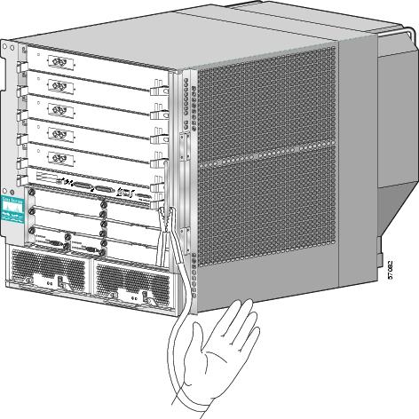
Figure 2 Connecting an ESD-preventive Wrist Strap to the Chassis
Removing and Installing a CSC or an SFC
The CSCs occupy the half-width slots on the lower left side of the chassis, under the RP and line card cage. (See Figure 1.) The three SFCs occupy the three half-width slots on the lower right side of the chassis.
Note
The CSC blank filler uses the same release levers and captive screws as the CSC, so the blank filler is removed and installed the same way as the CSC. The removal and installation procedures in the following sections apply equally to the CSC blank fillers.Procedures for removing and installing a CSC or an SFC are described in these sections:
•
•
Removing and Installing a CSC
A Cisco 12006 or Cisco 12406 Router configured for redundant CSCs will have two CSCs installed in the two CSC slots; a router configured for nonredundant operation will have one CSC installed in one of the CSC slots, and will have a CSC blank filler installed in the second CSC slot. (See Figure 1.) Figure 3 shows a partially ejected CSC.
Figure 3 Removing and Installing a CSC
Caution
Caution
Procedures for removing and installing a CSC are described in these sections:
•
Removing a CSC
To remove a CSC (or CSC blank filler), see Figure 3 and follow these steps:
Step 1
Step 2
Step 3
Step 4
Step 5
Step 6
Caution
Step 7
Installing a CSC
To install a CSC (or CSC blank filler), see Figure 3 and follow these steps:
Step 1
Step 2
Caution
Step 3
Caution
Step 4
Step 5
Step 6
Step 7
Caution
Step 8
Verifying the Installation of the Clock and Scheduler Card
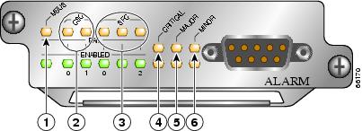
To verify router operation after installing a replacement CSC, visually check the LEDs on the two alarm cards. (See Figure 4.) When the system is operating normally, the following LED conditions should be true.
LEDs that normally should be on:
•
•
•
LEDs that normally should be off:
•
•
•
•
Figure 4 Alarm Card LEDs On/Off Conditions
MBus status LED
Critical alarm LED
CSC status LEDs (two)
Major alarm LED
SFC status LEDs (three)
Minor alarm LED
Removing and Installing an SFC
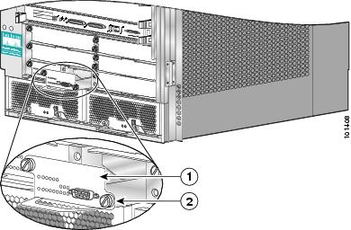
The three SFCs occupy the three half-width slots on the lower right side of the chassis. (See Figure 1.) Figure 5 shows a partially-ejected SFC.
Figure 5 Removing and Installing a Switch Fabric Card
Note
Caution
Procedures for removing and installing an SFC are described in these sections:
•
Removing an SFC
To remove an SFC, see Figure 5 and follow these steps:
Step 1
Step 2
Step 3
Step 4
Step 5
Step 6
Step 7
Installing an SFC
To install an SFC, see Figure 5 and follow these steps:
Step 1
Step 2
Caution
Step 3
Caution
Step 4
Step 5
Step 6
Step 7
Caution
Step 8
Verifying the Installation of the SFC
To verify router operation after installing a replacement SFC, see the "Verifying the Installation of the Clock and Scheduler Card" section. The description of the alarm card LEDs applies equally to checking SFC operation.
Removing and Installing an Alarm Card
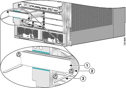
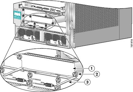
The two alarm cards occupy the card slots in the alarm card bay. These slots are located on the bottom left side of the chassis, directly underneath the CSC slots. (See Figure 1.) Figure 6 shows a partially-ejected alarm card.
Figure 6 Removing and Installing an Alarm Card
Note
Procedures for removing and installing an alarm card are described in the following sections:
•
Removing an Alarm Card
To remove an alarm card, see Figure 6 and follow these steps:
Step 1
Step 2
Step 3
Step 4
Step 5
Step 6
Installing an Alarm Card
To install an alarm card, see Figure 6 and follow these steps:
Step 1
Step 2
Caution
Step 3
Step 4
Step 5
Caution
Step 6
Verifying the Installation of the Alarm Card
To verify router operation after installing a replacement alarm card, see the "Verifying the Installation of the Clock and Scheduler Card" section. The description of the alarm card LEDs applies equally to checking alarm card operation.
Troubleshooting the Switch Fabric
This section describes the procedures needed to troubleshoot problems with the switch fabric. The RP and the line cards connect through the crossbar switch fabric, which provides a high-speed physical path for most inter-card communication. Among the messages passed between the RP and the line cards over the switch fabric are, actual packets being routed and received, forwarding information, traffic statistics, and most management and control information. This information is useful in diagnosing hardware-related failures.
Note
To troubleshoot the switch fabric, follow these steps:
Step 1
Note
Step 2
Step 3
Step 4
Step 5
Analyzing the Data
Switch fabric problems can occur due to failures in any of the following components:
•
•
•
•
When troubleshooting switch fabric errors, you need to look for patterns with regard to which components are reporting errors. For example, if you combine the show controllers fia output from all the RPs and line cards, you can determine if there is an error pattern. The following subsections discuss the values within the output that can help you determine any error patterns.
Note
crc16 Output
The crc16 data line from the show controllers fia command is an important indicator of hardware problems. If one line card or one CSC/SFC has been on line inserted and removed, you can expect to see some crc16 error data. However, this number should not continue to increase. If the number is increasing, you might need to replace some faulty hardware. It is very important to correlate the data from both the primary RP and the secondary RP and all installed line cards. The example output below shows the status of the primary RP. The crc16 data line is underlined and is showing errors from sfc1.
Router#show controllers fiaFabric configuration: Full bandwidth, redundant fabricMaster Scheduler: Slot 17 Backup Scheduler: Slot 16From Fabric FIA Errors-----------------------redund fifo parity 0 redund overflow 0 cell drops 0crc32 lkup parity 0 cell parity 0 crc32 0Switch cards present 0x001F Slots 16 17 18 19 20Switch cards monitored 0x001F Slots 16 17 18 19 20Slot: 16 17 18 19 20Name: csc0 csc1 sfc0 sfc1 sfc2-------- -------- -------- -------- --------los 0 0 0 0 0state Off Off Off Off Offcrc16 0 0 0 1345 0To Fabric FIA Errors-----------------------sca not pres 0 req error 0 uni FIFO overflow 0grant parity 0 multi req 0 uni FIFO undrflow 0cntrl parity 0 uni req 0 crc32 lkup parity 0multi FIFO 0 empty dst req 0 handshake error 0cell parity 0In the example output below, you can see the status of the line card in slot 2. The crc16 data line is underlined and is showing errors from sfc1. Remember to use the attach command and not the execute-on command to access the line cards.
Router#attach 2Entering Console for 4 port ATM Over SONET OC-3c/STM-1 in Slot: 2Type "exit" to end this sessionPress RETURN to get started!LC-Slot2>LC-Slot2>enableLC-Slot2#show controllers fiaFrom Fabric FIA Errors-----------------------redund FIFO parity 0 redund overflow 0 cell drops 0crc32 lkup parity 0 cell parity 0 crc32 0Switch cards present 0x001F Slots 16 17 18 19 20Switch cards monitored 0x001F Slots 16 17 18 19 20Slot: 16 17 18 19 20Name: csc0 csc1 sfc0 sfc1 sfc2-------- -------- -------- -------- --------Los 0 0 0 0 0state Off Off Off Off Offcrc16 0 0 0 1345 0To Fabric FIA Errors-----------------------sca not pres 0 req error 0 uni fifo overflow 0grant parity 0 multi req 0 uni fifo undrflow 0cntrl parity 0 uni req 0 crc32 lkup parity 0multi fifo 0 empty DST req 0 handshake error 0cell parity 0LC-Slot2#exitDisconnecting from slot 2.Connection Duration: 00:00:21Router#Once you have gathered the show controllers fia command data from the RPs and line cards, you can create a table similar to Table 1.
Table 1 Error Data Collection Table
0
ERROR
1
2
ERROR
3
ERROR
4
5
ERROR
This table indicates that more than one line card is reporting errors coming from SFC 1. Therefore, the first step is to change this SFC. Whenever a replacement is recommended, first verify that the card is correctly seated. You should ALWAYS reseat the corresponding card to be sure it is correctly seated. If, after reseating the card, the CRCs are still increasing, then go ahead and replace the part. See the "Properly Seating Switch Fabric Cards" section.
The common failure patterns and recommended actions for crc16 errors are as follows (one step at a time until the problem goes away):
1.
a.
b.
c.
2.
a.
b.
c.
Grant Parity and Request Errors
Another troubleshooting indicator comes from the console logs or the output of the show log command, in the form of grant parity and request errors. Look for the following type of message that indicates a grant parity error:
%FABRIC-3-PARITYERR: To Fabric parity error was detected.Grant parity error Data = 0x2.SLOT 1:%FABRIC-3-PARITYERR: To Fabric parity error was detected.Grant parity error Data = 0x1You can also use the output from the show controllers fia command. Important information is underlined:
Router#show controllers fiaFabric configuration: Full bandwidth, redundant fabricMaster Scheduler: Slot 17 Backup Scheduler: Slot 16From Fabric FIA Errors-----------------------redund FIFO parity 0 redund overflow 0 cell drops 76crc32 lkup parity 0 cell parity 0 crc32 0Switch cards present 0x001F Slots 16 17 18 19 20Switch cards monitored 0x001F Slots 16 17 18 19 20Slot: 16 17 18 19 20Name: csc0 csc1 sfc0 sfc1 sfc2-------- -------- -------- -------- --------Los 0 0 0 0 0state Off Off Off Off Offcrc16 876 257 876 876 876To Fabric FIA Errors-----------------------sca not pres 0 req error 1 uni fifo overflow 0grant parity 1 multi req 0 uni fifo undrflow 0cntrl parity 0 uni req 0 crc32 lkup parity 0multi fifo 0 empty DST req 0 handshake error 0cell parity 0The common failure patterns and recommended actions for grant parity and request errors are as follows (one step at a time until the problem goes away):
1.
a.
b.
2.
a.
a.
b.
Note
Properly Seating Switch Fabric Cards
The switch fabric cards in the router can be challenging to insert, and may require a small amount of force to seat correctly. If either of the CSCs are not seated properly, you may see the following error message:
%MBUS-0-NOCSC: Must have at least 1 CSC card in slot 16 or 17%MBUS-0-FABINIT: Failed to initialize switch fabric infrastructure
Note
When dealing with switch fabric and line card booting problems, it is important to verify that all CSCs and SFCs are correctly seated and powered on. The output from the show version and show controllers fia commands tells you which hardware configuration is currently running on the box. Important data is underlined.
Router#show versionCisco Internetwork Operating System SoftwareIOS (tm) GS Software (GSR-P-M), Experimental Version 12.0(20010505:112551)Copyright (c) 1986-2001 by cisco Systems, Inc.Compiled Mon 14-May-01 19:25 by tmcclureImage text-base: 0x60010950, data-base: 0x61BE6000ROM: System Bootstrap, Version 11.2(17)GS2, [htseng 180]EARLY DEPLOYMENT RELEASE SOFTWARE (fc1)BOOTFLASH: GS Software (GSR-BOOT-M), Version 12.0(15.6)S,EARLY DEPLOYMENT MAINTENANCE INTERIM SOFTWARERouter uptime is 17 hours, 53 minutesSystem returned to ROM by reload at 23:59:40 MET Mon Jul 2 2001System restarted at 00:01:30 MET Tue Jul 3 2001System image file is "tftp://172.17.247.195/gsr-p-mz.15S2plus-FT-14-May-2001"cisco 12016/GRP (R5000) processor (revision 0x01) with 262144K bytes of memory.R5000 CPU at 200Mhz, Implementation 35, Rev 2.1, 512KB L2 CacheLast reset from power-on2 Route Processor Cards1 Clock Scheduler Card3 Switch Fabric Cards1 8-port OC3 POS controller (8 POs).1 OC12 POS controller (1 POs).1 OC48 POS E.D. controller (1 POs).7 OC48 POS controllers (7 POs).1 Ethernet/IEEE 802.3 interface(s)17 Packet over SONET network interface(s)507K bytes of non-volatile configuration memory.20480K bytes of Flash PCMCIA card at slot 0 (Sector size 128K).8192K bytes of Flash internal SIMM (Sector size 256K).Router#show controller fiaFabric configuration: Full bandwidth nonredundantMaster Scheduler: Slot 17Additional troubleshooting information is available on Cisco.com.
Regulatory, Compliance, and Safety Information
This section includes regulatory, compliance, and safety information in the following sections:
•
•
Translated Safety Warnings and Agency Approvals
The complete list of translated safety warnings and agency approvals is available in the Regulatory Compliance and Safety Information for Cisco 12000 Series Routers publication (Document Number 78-4347-xx).
Electromagnetic Compatibility Regulatory Statements
FCC Class A Compliance
This equipment has been tested and found to comply with the limits for a Class A digital device, pursuant to part 15 of the FCC rules. These limits are designed to provide reasonable protection against harmful interference when the equipment is operated in a commercial environment. This equipment generates, uses, and can radiate radio-frequency energy and, if not installed and used in accordance with the instruction manual, may cause harmful interference to radio communications. Operation of this equipment in a residential area is likely to cause harmful interference, in which case users will be required to correct the interference at their own expense.
Modifying the equipment without Cisco's authorization may result in the equipment no longer complying with FCC requirements for Class A digital devices. In that event, your right to use the equipment may be limited by FCC regulation and you may be required to correct any interference to radio or television communication at your own expense.
You can determine whether your equipment is causing interference by turning it off. If the interference stops, it was probably caused by the Cisco equipment or one of its peripheral devices. If the equipment causes interference to radio or television reception, try to correct the interference by using one or more of the following measures:
•
•
•
•
CISPR 22
This apparatus complies with CISPR 22/EN55022 Class B radiated and conducted emissions requirements.
Canada
English Statement of Compliance
This class A digital apparatus complies with Canadian ICES-003.
French Statement of Compliance
Cet appareil numérique de la classe A est conforme à la norme NMB-003 du Canada.
Europe (EU)
This apparatus complies with EN55022 Class B and EN55024 standards when used as ITE/TTE equipment, and EN300386 for Telecommunications Network Equipment (TNE) in both installation environments, telecommunication centers and other indoor locations.
VCCI Class A Notice for Japan
Class A Notice for Hungary
Class A Notice for Taiwan and Other Traditional Chinese Markets
Class A Notice for Korea
Obtaining Documentation and Submitting a Service RequestFor information on obtaining documentation, submitting a service request, and gathering additional information, see the monthly What's New in Cisco Product Documentation, which also lists all new and revised Cisco technical documentation, at:
http://www.cisco.com/en/US/docs/general/whatsnew/whatsnew.html
Subscribe to the What's New in Cisco Product Documentation as a Really Simple Syndication (RSS) feed and set content to be delivered directly to your desktop using a reader application. The RSS feeds are a free service and Cisco currently supports RSS version 2.0.
This document is to be used in conjunction with the Cisco 12006 and Cisco 12406 Router Installation and Configuration Guide.
CCDE, CCENT, Cisco Eos, Cisco Lumin, Cisco Nexus, Cisco StadiumVision, the Cisco logo, DCE, and Welcome to the Human Network are trademarks; Changing the Way We Work, Live, Play, and Learn is a service mark; and Access Registrar, Aironet, AsyncOS, Bringing the Meeting To You, Catalyst, CCDA, CCDP, CCIE, CCIP, CCNA, CCNP, CCSP, CCVP, Cisco, the Cisco Certified Internetwork Expert logo, Cisco IOS, Cisco Press, Cisco Systems, Cisco Systems Capital, the Cisco Systems logo, Cisco Unity, Collaboration Without Limitation, EtherFast, EtherSwitch, Event Center, Fast Step, Follow Me Browsing, FormShare, GigaDrive, HomeLink, Internet Quotient, IOS, iPhone, iQ Expertise, the iQ logo, iQ Net Readiness Scorecard, iQuick Study, IronPort, the IronPort logo, LightStream, Linksys, MediaTone, MeetingPlace, MGX, Networkers, Networking Academy, Network Registrar, PCNow, PIX, PowerPanels, ProConnect, ScriptShare, SenderBase, SMARTnet, Spectrum Expert, StackWise, The Fastest Way to Increase Your Internet Quotient, TransPath, WebEx, and the WebEx logo are registered trademarks of Cisco Systems, Inc. and/or its affiliates in the United States and certain other countries.
All other trademarks mentioned in this document or Website are the property of their respective owners. The use of the word partner does not imply a partnership relationship between Cisco and any other company. (0805R)
Copyright © 2008 Cisco Systems, Inc. All rights reserved.