Table Of Contents
Troubleshooting the Uplink Cards
Verifying the Uplink Card Connection
LEDs
DPT and POS/DPT Uplink Card LEDs
RPR/SRP Uplink Card LEDs
Troubleshooting the Uplink Cards Installation
Fiber Misconnection—DPT Uplink Cards
Fiber Misconnection—RPR/SRP Uplink Card
Alarm Messages
Troubleshooting the RPR/SRP Uplink Card Installation
Troubleshooting the POS Uplink Card Installation
Alarm Processing
Loopback Testing
Additional Troubleshooting Resources
Cleaning the Fiber-Optic Connections
Troubleshooting the Uplink Cards
This chapter contains the following sections:
•Verifying the Uplink Card Connection
•LEDs
•Troubleshooting the Uplink Cards Installation
•Troubleshooting the RPR/SRP Uplink Card Installation
•Additional Troubleshooting Resources
•Cleaning the Fiber-Optic Connections
Verifying the Uplink Card Connection
Read the following troubleshooting tips to help verify a successful uplink card connection with the system:
•Verify LED status by checking uplink card LED color. (See all the tables in the "LEDs" section.)
•Verify that the card is fully seated against the midplane.
•Verify that all cables are properly connected.
•Verify that the cable types are correct (RPR card cables, for example, are all single-mode).
•Verify that RX and TX are properly connected.
•Verify that side A and side B are properly connected for SRP.
•Verify that span East and span West are properly connected for the RPR/SRP card.
•Verify that there are no duplicate MAC addresses.
•Check the power source:
–Power switch is turned to the on (-) position.
–Power supply connection is secure.
–DC power is turned on at the circuit breaker.
LEDs
The following LED information is found in this section:
•DPT and POS/DPT Uplink Card LEDs
•RPR/SRP Uplink Card LEDs
DPT and POS/DPT Uplink Card LEDs
Information on both uplink card specific LEDs and system LEDs for the DPT and POS/DPT uplink cards is in this section.
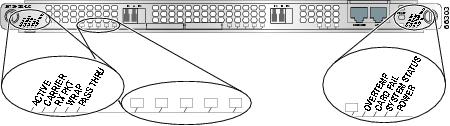
The LEDs located on the left side of the DPT and POS/DPT uplink card provide DPT and POS uplink status information. (See Figure 5-1.) For POS/DPT uplink cards, the LED information is dependent on whether the card is configured as POS or DPT. (See Table 5-1 and Table 5-2.)
See Table 5-3 for system LED information for the DPT and POS/DPT cards.
Figure 5-1 DPT and POS/DPT Uplink Card LEDs
Table 5-1 DPT Uplink Status LEDs
LED
|
Activity
|
Description
|
ACTIVE
|
Green
|
Port is active.
|
|
Blinking red
|
Fiber misconnect is detected (that is, side A connected to neighbor side A). There is no TX optical power.
|
|
Off
|
Port is not active.
|
CARRIER
|
Green
|
Framer has locked onto the SONET frames.
|
|
Off
|
Framer has not achieved lock.
|
RX PACKET
|
Green
|
Packets are being received on the port.1
|
|
Off
|
No packets are being received on the port.
|
WRAP or SRP WRAP
|
Green
|
Wrap in system (for example, another station on the ring is wrapped).
|
|
Red
|
Port is in local wrap.
|
|
Off
|
No wrap (for example, port is operating normally).
|
PASSTHRU or SRP PASS THRU
|
Green
|
Port is in passthru mode.
|
|
Off
|
Port is operating normally.
|
Table 5-2 POS/DPT Uplink Status LEDs
LED
|
Activity
|
Description
|
ACTIVE
|
Green
|
Port is active.
|
|
Off
|
Port is not active.
|
CARRIER
|
Green
|
Framer has locked onto the SONET frames.
|
|
Off
|
Framer has not achieved lock.
|
RX PACKET
|
Green
|
Packets are being received on the port.
|
|
Off
|
No packets are being received on the port.
|
SRP WRAP
|
Off
|
Not applicable to POS.
|
SRP PASS THRU
|
Off
|
Not applicable to POS.
|
The LEDs located on the right side of the uplink card provide system status information.
Note Table 5-3 also indicates the system status of the card as it initializes.
Table 5-3 DPT and POS/DPT System LEDs
LED
|
Activity
|
Description
|
OVERTEMP
|
Green (default status when initialized)
|
System is operating within the proper temperature range. (inlet <104oF [40oC]; outlet <109oF [43oC])
|
|
Red/green
|
Both LEDs are on, (appears orange). System is working on warning temperature range. (104oF [40oC] <= inlet < 122oF [50oC], 109oF [43oC] <= outlet < 127oF [53oC])
|
|
Red
|
System is working on critical temperature state. (122oF [50oC] <= inlet < 149oF [65oC], 127oF [53oC] <= outlet < 167oF [75oC])
|
CARD FAIL
|
Red
|
A hardware failure is detected on the uplink card. During power up, the LED will be red even when the uplink card is powered down.
|
|
Off (default status when initialized)
|
Card is operational. The LED is turned off after hardware initialization.
|
SYSTEM STATUS
|
Red
|
Not applicable.
|
|
Red/green
|
Both LEDs are on (appears orange). This is the normal configuration during power up. Once the software loads successfully, the red LED will turn off.
|
|
Green (default status when initialized)
|
System is operational.
|
POWER
|
Green (default status when initialized)
|
Uplink card is receiving power from the system.1
|
|
Off
|
Uplink card is not receiving power from the system.
|
RPR/SRP Uplink Card LEDs
Information on both uplink card specific LEDs and system LEDs for the RPR/SRP uplink cards is located in this section.
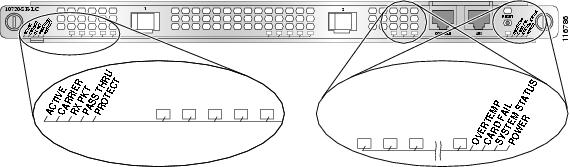
The LEDs located on the left side of the RPR/SRP uplink card provide RPR and SRP uplink status information. See Figure 5-2 and Table 5-4. The system LEDs are located on the right side of the RPR/SRP uplink card. See Table 5-5.
Figure 5-2 RPR/SRP Uplink Status LEDs
Note Note that the RPR/SRP uplink card uses the label "PROTECT" instead of "WRAP", and the positions of these two LEDs are different from that on the DPT or POS/DPT uplink card.
Table 5-4 RPR/SRP Uplink Status LEDs
LED
|
Activity
|
Description
|
ACTIVE
|
Green
|
Port is enabled by software. There is no side mismatch or loopback.
|
Amber
|
Loopback is on.
|
Blinking amber
|
Port is enabled by software and there is a side mismatch. There is no loopback.
|
Off
|
Port is not enabled by software
|
CARRIER
|
Green
|
Port is up and there is a valid SONET signal without any alarms.
|
Amber
|
Port is up and there is at least one alarm (LOS, LOF, RDI, and so on.)
|
Off
|
Off.
|
RX PKT
|
Green
|
Framer is receiving packets.
|
Off
|
Framer is not receiving packets.
|
PASSTHRU
|
Green
|
Port is in passthrough mode.
|
Off
|
Port is operating normally.
|
PROTECT
|
Green
|
Remote wrap.
|
Off
|
No wrap.
|
Amber
|
Local wrap.
|
Blinking green
|
Remote steer.
|
Blinking amber
|
Local steer.
|
The LEDs located on the right side of the uplink card provide system status information.
Note Table 5-5 also indicates the system status of the card as it initializes.
Table 5-5 RPR/SRP Uplink Card System LEDs
LED
|
Activity
|
Description
|
OVERTEMP
|
Green (default status when initialized)
|
System is operating within the proper temperature range. (inlet <104oF [40oC]; outlet <109oF [43oC])
|
|
Amber/green
|
Both LEDs are on, (appears orange). System is working on warning temperature range. (104oF [40oC] <= inlet < 122oF [50oC], 109oF [43oC] <= outlet < 127oF [53oC])
|
|
Amber
|
System is working on critical temperature state. (122oF [50oC] <= inlet < 149oF [65oC], 127oF [53oC] <= outlet < 167oF [75oC])
|
CARD FAIL
|
Amber
|
A hardware failure is detected on the uplink card. During power up, the LED will be amber even when the uplink card is powered down.
|
|
Off (default status when initialized)
|
Card is operational. The LED is turned off after hardware initialization.
|
SYSTEM STATUS
|
Amber
|
Not applicable.
|
|
Amber/green
|
Both LEDs are on (appears orange). This is the normal configuration during power up. Once the software loads successfully, the amber LED will turn off.
|
|
Green (default status when initialized)
|
System is operational.
|
POWER
|
Green (default status when initialized)
|
Uplink card is receiving power from the system.1
|
|
Off
|
Uplink card is not receiving power from the system.
|
Troubleshooting the Uplink Cards Installation
Read the following troubleshooting tips to help verify a successful installation of the uplink cards:
•Fiber Misconnection—DPT Uplink Cards
•Fiber Misconnection—RPR/SRP Uplink Card
•Alarm Messages
Fiber Misconnection—DPT Uplink Cards
Check for misconnected fiber cables (Side A to side A, TX to TX, span East to span East, and so forth) using the show srp command. Misconnection Alarm appears at the top of the show srp command output.
•One alarm—Problem is with another node on the ring; for example, side A connected to side A.
•Two alarms—Problem is your node.; for example, side A to side A and side B to side B.
•Ensure that the duplex cables are not misconnected.
Fiber Misconnection—RPR/SRP Uplink Card
Check for misconnected fiber cables (span West to span West or TX to TX, and so forth) using the show rpr-ieee protection command. Misconnection Alarm appears at the bottom of the show rpr-ieee protection command output.
•One alarm—Problem is with another node on the ring; for example, side West connected to side West.
•Two alarms—Problem is your node; for example, span West to span West and span Eastto apan East
•Ensure that the duplex cables are not misconnected.
Alarm Messages
The following alarm messages report to the console. See Table 5-6 through Table 5-13 for specific alarms and solutions.
The suggested solutions listed below are to the most commonly observed errors:
•Keepalive Alarm Messages for All Uplink Cards, Table 5-6
•IEEE 802.17 RPR Wrap Messages, Table 5-7
•IEEE 802.17 RPR Unwrap Message, Table 5-8
•Other IEEE 802.17 RPR Alarm Messages, Table 5-11
•SRP Wrap Messages, Table 5-12
•SRP Unwrap Message, Table 5-13
Table 5-6 Keepalive Alarm Messages for All Uplink Cards
Alarm
|
Description
|
Solution
|
SRP1/1 Side A Keepalive Failure (MAC)
|
MAC failure is detected
|
Check transport span for problems.
Typically SRP ring traverses a SONET layer connection, creating this error.
|
SRP1/1 Side A Keepalive Failure (SLOS)
|
SONET section loss of signal
|
Check fiber for breaks, power level, and connectivity.
This is a SONET Layer 1 issue with fiber.
|
SRP1/1 Side A Keepalive Failure (SLOF)
|
SONET section loss of frame
|
Check the fiber for degradation in (power level) or clocking (internal versus line).
|
SRP1/1 Side A Keepalive Failure (LSD)
|
SONET line signal degrade
|
Check the affected fiber, transmit and receive ports. Check power level.
This is a SONET Layer 1 issue with signal degrade.
|
SRP1/1 Side A Keepalive Failure (LSD)
|
SONET line signal degrade
|
Check the neighbor node/transport/regenerator for SONET Layer 1 issues (LOS, LSF).
This is a SONET Layer 1 issue with an intermediate unit (usually transport connection or regenerator) forwarding an AIS.
|
SRP1/1 Side A Keepalive OK
|
Keepalive failure removed; Layer 2 Keepalive receiving correctly
|
None.
|
RPR-IEEE1/1 span WEST Keepalive Failure (MAC)
|
MAC failure is detected
|
Check transport span for problems.
Typically RPR ring traverses a SONET layer connection, creating this error.
|
RPR-IEEE1/1 span WEST Keepalive Failure (SLOS)
|
SONET section loss of signal
|
Check fiber for breaks, power level, and connectivity.
This is a SONET Layer 1 issue with fiber.
|
RPR-IEEE1/1 span WEST Keepalive Failure (SLOF)
|
SONET section loss of frame
|
Check the fiber for degredation in (power level) or clocking (interval versus line).
|
RPR-IEEE1/1 span WEST Keepalive Failure (LSD)
|
SONET line signal degrade
|
Check the affected fiber transmit (TX) and receive (RX) ports. Check the power level.
This is a SONET Layer 1 issue with signal degradation.
|
RPR-IEEE1/1 span WEST Keepalive Failure (LSF)
|
SONET line signal failure
|
Check the neighboring node/transport/regenerator for SONET Layer 1 issues (LOS, LSF).
This is a SONET Layer 1 issue with an intermediate unit (usually transport connection or regenerator) forwarding an AIS.
|
RPR-IEEE1/1 span WEST Keepalive Failure OK
|
Keepalive signal removed, Layer 2 Keepalive receiving correctly
|
None.
|
Table 5-7 IEEE 802.17 RPR Wrap Messages
Alarm
|
Description
|
Solution
|
RPR-IEEE1/1 wrapped on span East (span WEST User Request Forced Switch)
|
User initiated forced switch on span WEST on node
|
User initiated, none.
|
RPR-IEEE1/1 wrapped on span EAST (span WEST User Request Manual Switch)
|
User initiated manual switch on span WEST on node
|
User initiated, none.
|
RPR-IEEE1/1 wrapped on span EAST (span WEST Self Detect Signal Fail)
|
SONET Layer 1 signal fail detected
|
Investigate Keepalive failure. Wrap occurred.
Keepalive failure—SLOS, SLOF, LSF, or LAIS.
|
RPR-IEEE1/1 wrapped on span EAST (span WEST Span Neighbor Signal Degrade)
|
SONET Layer 1 signal fail detected
|
Investigate Keepalive failure. Wrap occurred.
Keepalive failure—LSD.
|
RPR-IEEE1/1 wrapped on span EAST (span WEST Self Detect Wait to Restore [WTR])
|
Wrap cleared, node initiated; Wait to Restore (WTR) state
|
WTR period is 10 to 360 seconds (user configured), node will unwrap at end of WTR. None.
|
RPR-IEEE1/1 wrapped on span EAST (span WEST Span Neighbor Forced Switch)
|
Neighbor node Forced Switch initiated by user. Node wrap to protect failed span
|
User initiated, none.
|
RPR-IEEE1/1 wrapped on span EAST (span WEST Span Neighbor Manual Switch)
|
Neighbor node Manual Switch initiated by user. Node wrap
|
User initiated, none.
|
RPR-IEEE1/1 wrapped on span EAST (span WEST Span Neighbor Signal Fail)
|
Neighbor node wrapped due to signal fail
|
Investigate the signal degrade on neighbor node.
|
RPR-IEEE1/1 wrapped on span EAST (span WEST Span Neighbor Signal Degrade)
|
Neighbor node wrapped due to signal degrade
|
Investigate the signal degrade on neighbor node.
|
RPR-IEEE1/1 wrapped on span EAST (span WEST Span Neighbor WTR)
|
Wrap cleared, node initiated; Wait to Restore state
|
WTR period is 0 to 1440, or never (user configured), node will unwrap at end of WTR. None. Setting WTR to never will prevent the node from unwrapping.
|
RPR-IEEE1/1 wrapped on span EAST (span WEST Long Request Forced Switch)
|
Neighbor node Forced Switch initiated by user; Node wrap to protect failed span; Secondary problem on the short path
|
Investigate why the short path request was not received.
Check other problems on the short span as indicated on the neighbor node.
|
RPR-IEEE1/1 wrapped on span EAST (span WEST Long Request Manual Switch)
|
Neighbor node Manual Switch initiated by user; Node wrap to protect failed span; Secondary problem on the short path
|
Investigate why the short path request was not received.
Check other problems on the short span as indicated on the neighbor node.
|
RPR-IEEE1/1 wrapped on span EAST (span WEST Long Request Signal Fail)
|
Neighbor node wrapped due to signal fail
|
Investigate signal fail on neighbor node.
Investigate why the short path request was not received.
Check other problems on the short span as indicated on the neighbor node.
|
RPR-IEEE1/1 wrapped on span EAST (span WEST Long Request Signal Degrade)
|
Neighbor node wrapped due to signal degrade
|
Investigate signal degrade on neighbor node. Investigate why short path request was not received.
Check other problems on the short span as indicated on the neighbor node.
|
RPR-IEEE1/1 wrapped on span EAST (span WEST Long Request WTR)
|
Wrap cleared; Wait to Restore timer expired
|
None.
|
Table 5-8 IEEE 802.17 RPR Unwrap Message
Alarm
|
Description
|
Solution
|
RPR-IEEE1/1 unwrapped on span EAST (wrap cause cleared)
|
Wrap cleared; Wait to Restore timer expired.
|
None.
|
Table 5-9 IEEE 802.17 RPR Steer Messages
Alarm
|
Description
|
Solution
|
RPR-IEEE1/1 protected on span East (span WEST User Request Forced Switch)
|
User initiated forced switch on span WEST on node
|
User initiated, none.
|
RPR-IEEE1/1 protected on span EAST (span WEST User Request Manual Switch)
|
User initiated manual switch on span WEST on node
|
User initiated, none.
|
RPR-IEEE1/1 protected on span EAST (span WEST Self Detect Signal Fail)
|
SONET Layer 1 signal fail detected
|
Investigate Keepalive failure. Wrap occurred.
Keepalive failure—SLOS, SLOF, LSF, or LAIS.
|
RPR-IEEE1/1 protected on span EAST (span WEST Span Neighbor Signal Degrade)
|
SONET Layer 1 signal fail detected
|
Investigate Keepalive failure. Wrap occurred.
Keepalive failure—LSD.
|
RPR-IEEE1/1 protected on span EAST (span WEST Self Detect Wait to Restore [WTR])
|
Wrap cleared, node initiated; Wait to Restore (WTR) state
|
WTR period is 10 to 360 seconds (user configured), node will unwrap at end of WTR. None.
|
RPR-IEEE1/1 protected on span EAST (span WEST Span Neighbor Forced Switch)
|
Neighbor node Forced Switch initiated by user. Node wrap to protect failed span
|
User initiated, none.
|
RPR-IEEE1/1 protected on span EAST (span WEST Span Neighbor Manual Switch)
|
Neighbor node Manual Switch initiated by user. Node wrap
|
User initiated, none.
|
RPR-IEEE1/1 protected on span EAST (span WEST Span Neighbor Signal Fail)
|
Neighbor node protected due to signal fail
|
Investigate the signal degrade on neighbor node.
|
RPR-IEEE1/1 protected on span EAST (span WEST Span Neighbor Signal Degrade)
|
Neighbor node protected due to signal degrade
|
Investigate the signal degrade on neighbor node.
|
RPR-IEEE1/1 protected on span EAST (span WEST Span Neighbor WTR)
|
Wrap cleared, node initiated; Wait to Restore state
|
WTR period is 0 to 1440, or never (user configured), node will unwrap at end of WTR. None. Setting WTR to never will prevent the node from unwrapping.
|
RPR-IEEE1/1 protected on span EAST (span WEST Long Request Forced Switch)
|
Neighbor node Forced Switch initiated by user; Node wrap to protect failed span; Secondary problem on the short path
|
Investigate why the short path request was not received.
Check other problems on the short span as indicated on the neighbor node.
|
RPR-IEEE1/1 protected on span EAST (span WEST Long Request Manual Switch)
|
Neighbor node Manual Switch initiated by user; Node wrap to protect failed span; Secondary problem on the short path
|
Investigate why the short path request was not received.
Check other problems on the short span as indicated on the neighbor node.
|
RPR-IEEE1/1 protected on span EAST (span WEST Long Request Signal Fail)
|
Neighbor node protected due to signal fail
|
Investigate signal fail on neighbor node.
Investigate why the short path request was not received.
Check other problems on the short span as indicated on the neighbor node.
|
RPR-IEEE1/1 protected on span EAST (span WEST Long Request Signal Degrade)
|
Neighbor node protected due to signal degrade
|
Investigate signal degrade on neighbor node. Investigate why short path request was not received.
Check other problems on the short span as indicated on the neighbor node.
|
Table 5-10 IEEE 802.17 Un-Steer Messages
Alarm
|
Description
|
Solution
|
RPR-IEEE1/1 unprotected on span EAST (protection cause cleared)
|
Protection cleared; Wait to Restore timer expired.
|
None.
|
Table 5-11 Other IEEE 802.17 RPR Alarm Messages
Alarm
|
Description
|
Solution
|
RPR-IEEE1/1 Ringlet1 reserved A0 bandwidth has exceeded line rate
|
The amount of total A0 bandwidth on Ringlet1 reserved by all nodes on the ring exceeds the line rate
|
Check current A0 allocations on each station using the show rpr-ieee rate-limit command.
Change the A0 allocation on the ring by using the rpr-ieee tx-traffic reserved CLI command.
|
RPR-IEEE1/1 Ringtlet0 reserved A0 bandwidth has exceeded line rate
|
The amount of total A0 bandwidth on Ringlet0 reserved by all nodes on the ring exceeds the line rate
|
Check current A0 allocation on each station using the show rpr-ieee rate-limit command.
Change the A0 allocation on the ring by using the rpr-ieee tx-traffic reserved CLI command.
|
RPR-IEEE1/1 MAX Stations Exceeded
|
Too many stations have been discovered in the topology (maximum number of ring stations is 255)
|
Execute the show rpr-ieee topology commandto verify stations. Reduce the numer of stations in the ring.
|
RPR-IEEE1/1 Effective jumbo pref on ring is set for jumbo frames
|
All stations on the ring now support jumbo frame preference, MTU for the ring has been changed to JUMBO MTU (9100 bytes).
|
None. Remove jumbo preference on stations to revert to REGULAR MTU (1500 bytes)
|
RPR-IEEE1/1 Effective jumbo pref on ring is set for regular frame
|
At least one station on the ring does not support jumbo frame preference, MTU for the ring has been changed to REGULAR MTU (1500 bytes).
|
None. Configure jumbo preference on all stations to change support to JUMBO MTU (9100 bytes).
|
RPR-IEEE1/1 Effective protection mode on station is now steering
|
Protection preference has been changed. Protection mode for this station is now steering.
|
None.
|
RPR-IEEE1/1 Effective protection mode on station is now wrapping
|
Protection preference has been changed. Protection mode for this station is now wrapping.
|
None.
|
Configured protection mode is inconsistent with other stations on ring
|
Not all stations in the ring support the same protection preference (wrapping or steering). This inconsistency will create failures in a protection event.
|
Change all stations to support the same protection preference, all stations must support wrapping or steering. Use the show rpr-iee topology command to verify protection preference. Use the rpr protection preference wrap or no rpr protection preference wrap configuration command to change the preference.
|
Table 5-12 SRP Wrap Messages
Alarm
|
Description
|
Solution
|
SRP1/1 wrapped on side B (side A User Request Forced Switch)
|
User-initiated forced switch on side A on node
|
User initiated, none.
|
SRP1/1 wrapped on side B (side A User Request Manual Switch)
|
User-initiated manual switch on side A on node
|
User initiated, none.
|
SRP1/1 wrapped on side B (side A Self Detect Signal Fail)
|
SONET Layer 1 signal fail detected
|
Investigate Keepalive failure. Wrap occurred.
Keepalive failure—SLOS, SLOF, LSF, or LAIS.
|
SRP1/1 wrapped on side B (side A Span Neighbor Signal Degrade)
|
SONET Layer 1 signal fail detected
|
Investigate Keepalive failure. Wrap occurred.
Keepalive failure—LSD.
|
SRP1/1 wrapped on side B (side A Self Detect Wait to Restore [WTR])
|
Wrap cleared, node initiated Wait to Restore (WTR) state
|
WTR period is 10 to 360 seconds (user configured), node will unwrap at end of WTR. None.
|
SRP1/1 wrapped on side B (side A Span Neighbor Forced Switch)
|
Neighbor node Forced Switch initiated by user; Node wrap to protect failed span
|
User initiated, none.
|
SRP1/1 wrapped on side B (side A Span Neighbor Manual Switch)
|
Neighbor node Manual Switch initiated by user; Node wrap
|
User initiated, none.
|
SRP1/1 wrapped on side B (side A Span Neighbor Signal Fail)
|
Neighbor node wrapped due to signal fail
|
Investigate the signal fail on neighbor node.
|
SRP1/1 wrapped on side B (side A Span Neighbor Signal Degrade)
|
Neighbor node wrapped due to signal degrade
|
Investigate the signal degrade on neighbor node.
|
SRP1/1 wrapped on side B (side A Span Neighbor WTR)
|
Wrap cleared, node initiated Wait to Restore state
|
WTR period is 10 to 360 seconds (user configured), node will unwrap at end of WTR. None.
|
SRP1/1 wrapped on side B (side A Long Request Forced Switch)
|
Neighbor node Forced Switch initiated by user; Node wrap to protect failed span; Secondary problem on the short path
|
Investigate why the short path request was not received.
Check other problems on the short span as indicated on the neighbor node.
|
SRP1/1 wrapped on side B (side A Long Request Manual Switch)
|
Neighbor node Manual Switch initiated by user; Node wrap to protect failed span; Secondary problem on the short path
|
Investigate why the short path request was not received.
Check other problems on the short span as indicated on the neighbor node.
|
SRP1/1 wrapped on side B (side A Long Request Signal Fail)
|
Neighbor node wrapped due to signal fail
|
Investigate signal fail on neighbor node. Investigate why the short path request was not received.
Check other problems on the short span as indicated on the neighbor node.
|
SRP1/1 wrapped on side B (side A Long Request Signal Degrade)
|
Neighbor node wrapped due to signal degrade
|
Investigate signal degrade on neighbor node. Investigate why short path request was not received.
Check other problems on the short span as indicated on the neighbor node.
|
SRP1/1 wrapped on side B (side A Long Request WTR)
|
Wrap cleared, Wait to Restore timer expired
|
None.
|
Table 5-13 SRP Unwrap Message
Alarm
|
Description
|
Solution
|
SRP1/1 unwrapped on side B (side A Wrap cause cleared)
|
Wrap cleared, Wait to Restore timer expired
|
None.
|
Troubleshooting the RPR/SRP Uplink Card Installation
Use the transceiver keyword to display additional information about the status of the small form-factor pluggable (SFP) module used in an RPR port.
Router# show controllers rpr-ieee 1/1 transceiver
Show Transceiver: West Span
Gigabit Ethernet compliance: unspecified
Fibre Channel link length: unspecified
Fibre Channel transmitter technology: unspecified
Fibre Channel transmission media: unspecified
Fibre Channel speed: unspecified
Single mode fiber supported length: 2 km
Upper bit rate limit: unspecified
Lower bit rate limit: unspecified
Date code (yyyy/mm/dd): 2004/04/21
Vendor PN: SCP6828-C5-BNE
Vendor revision number: D
Vendor serial number: ECL0817001L
Transceiver status information
Diagnostics calibration is external
Temperature 39 (+/-3 Celsius)
Voltage in transceiver 3232600 uV (+/- 10 mV)
TX bias 8940 uA (+/- 100uA)
TX power 316000 nW / -5 dBm (+/- 3dBm)RX power 300200 nW / -5 dBm (+/- 3dBm)
TX power 1000000 nW / 0 dBm 50100 nW / -13 dBm
RX power 1008300 nW / 0 dBm unspecified
Voltage 3600000 uV 3000000 uV
TX power 630900 nW / -2 dBm 79400 nW / -11 dBm
RX power 1008300 nW / 0 dBm unspecified
Show Transceiver: East Span
Gigabit Ethernet compliance: unspecified
Fibre Channel link length: unspecified
Fibre Channel transmitter technology: unspecified
Fibre Channel transmission media: unspecified
Fibre Channel speed: unspecified
Single mode fiber supported length: 2 km
Upper bit rate limit: unspecified
Lower bit rate limit: unspecified
Date code (yyyy/mm/dd): 2004/04/21
Vendor PN: SCP6828-C5-BNE
Vendor revision number: D
Vendor serial number: ECL0817001M
Transceiver status information
Diagnostics calibration is external
Temperature 38 (+/-3 Celsius)
Voltage in transceiver 3230800 uV (+/- 10 mV)
TX bias 8724 uA (+/- 100uA)
TX power 285600 nW / -5 dBm (+/- 3dBm)
RX power 309900 nW / -5 dBm (+/- 3dBm)
TX power 1000000 nW / 0 dBm 50100 nW / -13 dBm
RX power 1008300 nW / 0 dBm unspecified
Voltage 3600000 uV 3000000 uV
TX power 630900 nW / -2 dBm 79400 nW / -11 dBm
RX power 1008300 nW / 0 dBm unspecified
Troubleshooting the POS Uplink Card Installation
This section provides information for troubleshooting the POS/DPT uplink card installation.
Alarm Processing
The following system alarms are monitored by the POS uplink card and reported to the console port:
•Loss-of-Signal (LOS)
•Loss-of-Frame (LOF)
•Line Alarm Indication Signal (LAIS)
•Line Remote Defect Indication (RDI)
•STS Path Loss-of-Pointer (LOP)
•STS Path Alarm Indication Signal (AIS)
•STS Path Remote Defect Indication (RDI)
•B1 Bit Error Rate (BER) threshold crossing alarm (b1-tca)
•B2 BER threshold crossing alarm (b2-tca)
•B3 BER threshold crossing alarm (b3-tca)
•Line Bit Interleave Parity (LBIP) BER in excess of signal degrade threshold (sd-ber)
•LBIP BER in excess of signal failure threshold (sf-ber)
At any time the status of the SONET/SDH alarm and signal events can be examined using the show controllers command, as shown in the following example:
Router# show controllers pos1/1
LOF = 0 LOS = 0 BIP(B1) = 0
AIS = 0 RDI = 0 FEBE = 0 BIP(B2) = 0
AIS = 0 RDI = 0 FEBE = 0 BIP(B3) = 0
LOP = 0 NEWPTR = 0 PSE = 0 NSE = 0
Alarm reporting enabled for: SF SLOS SLOF B1-TCA B2-TCA PLOP B3-TCA
State: PSBF_state = FALSE
Rx(K1/K2): 00/00 S1S0 = 00, C2 = CF
Remote aps status non-aps; Reflected local aps status non-aps
State: RDOOL_state = FALSE
PATH TRACE BUFFER : STABLE
Remote hostname : RouterB
Remote Rx(K1/K2): 00/00 Tx(K1/K2): 00/00
BER thresholds: SF = 10e-4 SD = 10e-6
TCA thresholds: B1 = 10e-6 B2 = 10e-6 B3 = 10e-6
RX readout values: -6 dBm
Loopback Testing
The POS uplink card supports two loopback modes for network testing, fault isolation, and agency compliance. The uplink card loopback modes are:
Internal loopback mode—Packets sent from the Cisco 10720 Internet Router out of the uplink card POS port TX optics are also looped back into the Cisco 10720 Internet Router.
Line loopback mode—Packets received by the POS uplink card port RX optics and sent into the Cisco 10720 Internet Router are also looped back out of the uplink card port TX optics.
Loopback testing is enabled through software. See the Cisco IOS Software Configuration for the Cisco 10720 Internet Router.
Additional Troubleshooting Resources
For more troubleshooting information for the uplink card, refer to the following publications:
•Chapter 4, "Troubleshooting", in the Cisco 10720 Internet Router Installation and Configuration Guide
•Cisco IOS Software Configuration for the Cisco 10720 Internet Router document
Cleaning the Fiber-Optic Connections
For information about cleaning fiber-optic cable connectors and receptacles, see the Inspection and Cleaning Procedures for Fiber-Optic Connections document. It provides detailed illustrations and photos of procedures and equipment required to properly clean fiber-optic connections.