Feedback Feedback
|
Table Of Contents
8-Port Fast Ethernet Half-Height Line Card Overview
Software and Hardware Compatibility
Line Card, Router, and Processor Compatibility
Cables, Connectors, and Pinouts
Cable and Connector Information
8-Port Fast Ethernet Half-Height Line Card Overview
This chapter describes the Cisco 10000 series 8-port fast Ethernet half-height line card (referred to as the 8-port fast Ethernet half-height line card), and contains the following sections:
•
Software and Hardware Compatibility
•
•
•
Line Card Summary
Table 9-1 8-Port Fast Ethernet Half-Height Line Card Summary
ESR-HH-8FE-TX=
8-port fast Ethernet half-height line card
Initial Cisco IOS releases for PRE-1:
12.0(23)S and later releases of Cisco IOS 12.0S
Initial Cisco IOS releases for PRE:2
12.2(15)BX and later releases of Cisco IOS 12.2BX12.2(28)SB and later releases of Cisco IOS Release 12.2(28)SB
12.3(7)XI and later releases of Cisco IOS 12.3 XIFor registered Cisco.com users, use Software Advisor to determine the software releases for this line card.
ESR-HH-CARRIER=
Full-length base carrier for half-slot line card
12.0(23)S and later releases of Cisco IOS 12.0S
12.2(28)SB and later releases of Cisco IOS Release 12.2(28)SB
ESR-HH-COVER=
Blank filler for half-height line cards
—
The 8-port fast Ethernet half-height line card contains eight 100BASE-TX ports. Each port autonegotiates between half and full duplex mode. Each port supports 100BASE-T, but does not support 10BASE-T.
The 8-port fast Ethernet half-height line card provides the Cisco 10000 series router with IEEE 802.3u-compliant 100BASE-TX Ethernet interfaces to provide high-density uplinks to devices (such as content servers, routers, and other Fast Ethernet devices). Because the 8-port fast Ethernet half-height line card only occupies one half-slot, each slot can support two Fast Ethernet line cards for a total of 16 ports. The Cisco 10000 supports multiple Fast Ethernet line cards. It is also acceptable to use the other subslot for a different half-height line card.
Note
If you are a registered Cisco.com user, see Feature Navigator for supported features.
Software and Hardware Compatibility
To check the minimum software requirements of Cisco IOS software with the hardware installed on your router, Cisco maintains the Software Advisor tool on Cisco.com. This tool does not verify whether line cards within a system are compatible, but does provide the minimum Cisco IOS requirements for individual hardware line cards, modules, or options.
Note
To access Software Advisor, click Login at Cisco.com, type Software Advisor in the SEARCH box, and click Go. Click the link for the Software Advisor tool.
Choose a product family or enter a specific product number to search for the minimum supported software release needed for your hardware.
Line Card, Router, and Processor Compatibility
Table 9-2 lists router model, line card, and processor compatibility.
Table 9-2 Line Card, Router, and Processor Compatibility
8-port fast Ethernet half-height line card
Yes
Yes
Yes
Yes
No
LEDs
The 8-port fast Ethernet half-height line card LEDs are shown in Figure 9-1.
Figure 9-1 8-Port Fast Ethernet Half-Height Line Card Faceplate Description
Table 9-3 provides a description of the 8-port fast Ethernet half-height LEDs.
Table 9-3 LED Description
Fail
Yellow
Off
Off when line card is working properly. Turns on for a few second during line card power-on self test (POST), then turns off when the line card is working properly.
On
On when the line card POST fails.
Link
Green
On
Lights when a valid Ethernet link is detected.
Off
Off when there is no valid Ethernet link.
Act (active)
Green
On
Lights to indicate there is activity on the link.1
Off
Off when there is no activity on the link.1
1 This behavior applies only to the 8-port fast Ethernet half-height line card.
Physical Specifications
The 8-port fast Ethernet half-height line card physical specifications are listed in Table 9-4.
Slot Locations
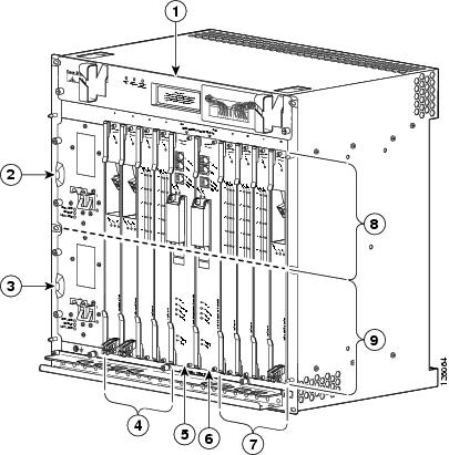
The line card slot designations are shown in this section. See Figure 9-2 for line card slot designations for the Cisco 10008 router and Figure 9-3 for line card slot designations for the Cisco 10005 router.
Figure 9-2 Line Card Slot and Subslot Designations for the Cisco 10008 Router
Blower module
PRE slot 0B
Primary PEM
Line card slots 5 to 8
Redundant PEM
Subslot 0
Line card slots 1 to 4
Subslot 1
PRE slot 0A
The 8-port fast Ethernet half-height line card can be installed in subslot 0 or subslot 1 of line card slot 1 through slot 8. The Cisco 10000 carrier is used with the 8-port fast Ethernet half-height line card.
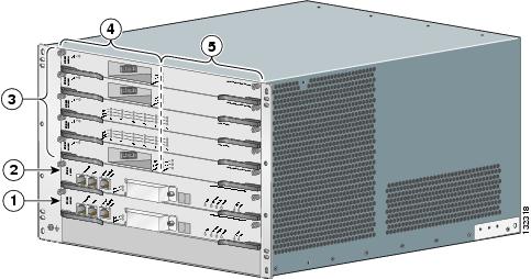
Figure 9-3 Line Card Slot and Subslot Designations for the Cisco 10005 Router
PRE slot A
Subslots 1/0 (top) to 5/0 (bottom)
PRE slot B
Subslots 1/1 (top) to 5/1 (bottom)
Line card slots 1 (top) to 5 (bottom)
The 8-port fast Ethernet half-height line card can be installed in any subslot in line card slot 1 through slot 5. The Cisco 10000 Carrier is used with the 8-Port Fast Ethernet Half Height line card.
Cables, Connectors, and Pinouts
This section provides information about cables, connectors, and pinouts.
Cable and Connector Information
The Cisco 10000 8-port fast Ethernet half-height line card includes eight RJ-45 connectors to which you can connect Category 5 UTP cables. Cable connections to the RJ-45 connectors are not intended for outside plant connections.
Note
Use the following cabling guidelines when planning your 100BASE-TX Fast Ethernet network:
•
•
–
–
Table 9-5 lists the maximum cable length between two nodes in a 100BASE-TX network.
Pinouts
Table 9-6 provides pinout information for the 8-port fast Ethernet half-height line card. The 8-port fast Ethernet half-height line card does not support software configuration of the MDI mode including auto-MDIX mode. It does not support Inter-Switch Link (ISL) encapsulation (the card does support 802.1Q VLAN encapsulation), or Fast EtherChannel.
Go to Chapter 16, "Preparing for Installation" to begin the installation or replacement of the line card.
For troubleshooting information, see Chapter 18, "Troubleshooting the Installation."