Feedback Feedback
|
Table Of Contents
24-Port Channelized E1/T1 Line Card Overview
Software and Hardware Compatibility
Line Card, Router, and Processor Compatibility
Cables, Connectors, and Pinouts
24-Port Channelized E1/T1 Line Card Overview
This chapter describes the Cisco 10000 series 24-port channelized E1/T1 line card (referred to as the 24-port channelized E1/T1 line card), and contains the following sections:
•
Software and Hardware Compatibility
•
•
•
Line Card Summary
Table 5-1 24-Port Channelized E1/T1 Line Card Summary
ESR-24CT1/E1=
24-port channelized T1/E1 line card
Initial Cisco IOS release for PRE-1:
12.0(22)S and later releases of Cisco IOS Release 12.0S
Initial Cisco IOS release for PRE-2:
12.2(15)BX and later releases of 12.2BX
2.2(28)SB and later releases of Cisco IOS Release 12.2(28)SB
12.3(7)XI and later releases of Cisco IOS 12.3XIFor registered Cisco.com users, use Software Advisor to determine the software releases for this line card.
The 24-port channelized E1/T1 line card provides Cisco 10000 routers with 24 copper channelized or unchannelized interface ports that you can configure as E1 or T1 interfaces. When you configure a line card for:
•
•
E1 Features
The E1 features of this line card support:
•
•
–
–
•
•
•
–
–
–
•
•
•
•
•
•
•
T1 Features
The T1 features of this line card support:
•
•
•
–
–
–
•
–
–
–
•
•
•
•
•
–
–
–
•
•
•
•
If you are a registered Cisco.com user, see Feature Navigator for supported features.
Software and Hardware Compatibility
To check the minimum software requirements of Cisco IOS software with the hardware installed on your router, Cisco maintains the Software Advisor tool on Cisco.com. This tool does not verify whether line cards within a system are compatible, but does provide the minimum Cisco IOS requirements for individual hardware line cards, modules, or options.
Note
To access Software Advisor, click Login at Cisco.com, type Software Advisor in the search box, and click Go. Click the link for the Software Advisor tool.
Choose a product family or enter a specific product number to search for the minimum supported software release needed for your hardware.
Line Card, Router, and Processor Compatibility
Table 5-2 lists router model, line card, and processor compatibility.
Table 5-2 Line Card, Router, and Processor Compatibility
24-port channelized E1/T1 line card
Yes
Yes
Yes
Yes
No
LEDs
The 24-port channelized E1/T1 line card LEDs are shown in Figure 5-1.
Figure 5-1 24-Port Channelized E1/T1 Line Card Faceplate Description
Table 5-3 provides a description of the 24-port channelized E1/T1 line card LEDs.
Physical Specifications
The 24-port channelized E1/T1 line card physical specifications are shown in Table 5-4.
Slot Locations
The line card slot designations are shown in this section. See Figure 5-2 for line card slot designations for the Cisco 10008 router and Figure 5-3 for line card slot designations for the Cisco 10005 router.
Figure 5-2 Line Card Slot Designations for the Cisco 10008 Router
Blower module
PRE slot 0A
Primary PEM
PRE slot 0B
Redundant PEM
Line card slots 5 to 8
Line card slots 1 to 4
The 24-port channelized E1/T1 line card can be installed in line card slot 1 through slot 8.
Figure 5-3 Line Card Slot Designations for the Cisco 10005 Router
The 24-port channelized E1/T1 line card can be installed in line card slot 1 through slot 5.
Cables, Connectors, and Pinouts
You can use up to 24 Category 3 or Category 5 unshielded twisted pair (UTP) transmit and receive cables with RJ-45 connectors at each end. These cables connect to two staggered 12-line faceplate RJ-45 jacks with 110-ohm balanced-line inputs, which allow the line card to operate in either T1 (100 ohm balanced) or E1 (120 ohm balanced) mode. The faceplate RJ-45 jacks are numbered 0 to 11 and 12 to 23 left-to-right and top-to-bottom.
You can also use a Cisco cable adapter (CAB-ADAPT-75-120=) for coaxial British Navel Connector (BNC) unbalanced transmit and receive E1 connections (see the "Using the BNC Cable Adapter" section).
Caution
Using the BNC Cable Adapter
Figure 5-4 shows the adapter cable available for the 24-port channelized E1/T1 line card.
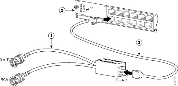
Figure 5-4 Faceplate, Connecting Cable, and Adapter Cable
An RJ-45 STP cable with two male RJ-45 connectors is required to connect the adapter cable and RJ-45 ports on the face of the line card (Figure 5-5).
Figure 5-5 75-120 Ohm Adapter Cable
Cisco cable adapters (CAB-ADAPT-75-120=) connect 75-ohm unbalanced G.703 E1 coaxial BNC transmit and receive lines to Cisco E1 120-ohm balanced transmit and receive lines.
The connections are made through eight-pin RJ-45 jacks on the 120-ohm side of the adapter cable and dual coaxial lines (transmit and receive) with BNC connectors at the 75-ohm side.
Class A emissions compliance is met when the 120-ohm E1 port is connected to the 75-120-ohm cable adapter using RJ-45 connectors and Category 3 or Category 5 shielded foil twisted-pair (FTP) cable with 120-ohm impedance. Two switches on the 120-ohm side must be configured to connect the outer conductor of the shielded cable to a protected earth ground (see enlargement in Figure 5-5).
Pinouts
Table 5-5 lists pinouts for the RJ-45 connector.
Table 5-5 RJ-45 Port Pinouts
1
RX tip
2
RX ring
3
No connection
4
TX tip
5
TX ring
6
No connection
7
No connection
8
No connection
Go to Chapter 16, "Preparing for Installation" to begin the installation or replacement of the line card.
For troubleshooting information, see Chapter 18, "Troubleshooting the Installation."