Table Of Contents
1.3 Power and Ground Description
1.4 Cable Description and Installation
1.4.2 Fiber Cable Installation
1.4.3 Coaxial Cable Installation
1.4.5 Alarm Cable Installation
Shelf Assembly Hardware
This chapter provides a description of Cisco ONS 15310-CL shelf hardware. Instructions for installing equipment are provided in the Cisco ONS 15310-CL Procedure Guide.
Chapter topics include:
•
Cable Description and Installation
•
Note
Note
1.1 Installation Overview
You can mount the ONS 15310-CL in a 19- or 23-inch (482.6 or 584.2 mm) rack or it can be placed on a flat surface using the installed rubber feet.
The shelf assembly weighs 11.5 pounds (5.22 kg) without a card installed and 12.5 pounds (5.67 kg) fully loaded. An ONS 15310-CL is installed in a rack using reversible mounting brackets on each side of the shelf.
The ONS 15310-CL is powered using -48 VDC or 100/240 VAC power. AC power terminals are accessible on the front panel and the DC power connection is accessed from the rear of the shelf assembly. The CRIT, MAJ, MIN, and REM alarm LEDs visible on the front of the node indicate whether a Critical, Major, Minor, or Remote alarm is present anywhere on the ONS 15310-CL assembly. These LEDs help you to determine quickly if any alarms are present on the assembly. You can access the ONS 15310-CL Ethernet card, small form-factor pluggables (SFPs), cables, and ports through the front of the shelf assembly only.
When installed in an equipment rack, the ONS 15310-CL assembly is typically connected to a fuse and alarm panel that provides centralized alarm connection points and distributed power for the ONS 15310-CL. Fuse and alarm panels are third-party equipment and are not described in this documentation. If you are unsure about the requirements or specifications for a fuse and alarm panel, consult the documentation for that product.
Note
Install the ONS 15310-CL in compliance with your local and national electrical codes:
•
•
•
1.2 Rack Installation
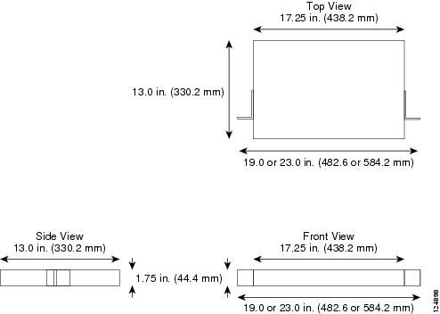
The ONS 15310-CL is easily mounted in a 19- or 23-inch (482.6 or 584.2 mm) equipment rack. The shelf assembly can be mounted so that it projects five inches from the front of the rack. It mounts in both EIA-standard and Telcordia-standard racks. The shelf assembly is a total of 17.25 inches (438.2 mm) wide.
The ONS 15310-CL measures 1.75 inches high, 19 or 23 inches wide (depending on which brackets are installed), and 15 inches deep (44.4 x 482.6 or 584.2 x 381 mm). Figure 1-1 shows the dimensions of the ONS 15310-CL shelf assembly.
Figure 1-1 ONS 15310-CL Shelf Assembly Dimensionst
Caution
Caution
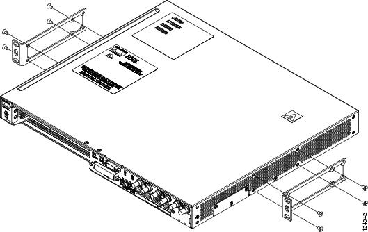
The shelf assembly comes with two mounting brackets, one for use with a 19-inch (482.6 mm) or 23-inch (584.2 mm) rack. Figure 1-2 shows the mounting bracket orientation for a 19-inch rack.
Figure 1-2 Mounting Brackets (23-Inch Orientation)
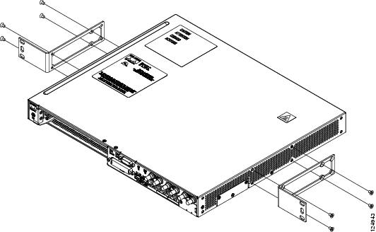
Figure 1-3 shows the mounting bracket orientations for a 23-inch rack. The brackets are installed in the same mounting holes for both rack sizes.
Figure 1-3 Mounting Brackets (19-Inch Orientation)
1.2.1 Mounting a Single Node
Mounting the ONS 15310-CL in a rack requires a minimum of 1.75 inches of vertical rack space (plus 1 inch [25.4 mm] for air flow). To ensure that the mounting is secure, use two #12-24 mounting screws for each side of the shelf assembly.
1.2.2 Mounting Multiple Nodes
Most standard seven-foot (2.1 m) racks can hold numerous ONS 15310-CL nodes and a fuse and alarm panel.
1.3 Power and Ground Description
This section describes how to connect the ONS 15310-CL shelf assembly to the power supply. For detailed procedures, refer to the "Install Hardware" chapter in the Cisco ONS 15310-CL Procedure Guide. Terminate the chassis ground on the rear of the shelf assembly to either the office ground or rack ground before you install the power. Use the grounding lug to attach the #6 AWG ground cable to the shelf assembly according to local site practice.
Ground one cable to ground the shelf assembly. Terminate the other end of the rack ground cable to ground according to local site practice.
If the system loses power or the 15310-CL-CTX card is reset, you must reset the ONS 15310-CL clock unless the node has been previously provisioned to use Simple Network Time Protocol (SNTP) to update the clock over the LAN.
Caution
Use the following wiring conventions:
•
•
Note
The ONS 15310-CL can be ordered with either AC or DC power capability. The DC power option provides redundant -48 VDC power terminals on the rear of the chassis. The terminals are labeled A and B and are located at each end of the shelf assembly. The ONS 15310-CL AC power connector is located at the bottom right on the front of the chassis. The power cables are provided with the ship kit.
To install redundant power feeds, use four power cables and one ground cable. For a single power feed, only two power cables and one ground cable are required. Use #14 AWG power cables and a #6 AWG ground cable and, to ensure circuit overcurrent protection, use a conductor with low impedance. However, the conductor must have the capability to safely conduct any fault current that might be imposed. Do not use aluminum conductors.
1.4 Cable Description and Installation
This section describes fiber-optic, DS-3/EC-1 (coaxial), DS-1 (96-pin LFH), UDC, and twisted-pair cables.
1.4.1 Cabling Types
The following types of cables are used with the ONS 15310-CL:
•
•
Note
•
•
1.4.2 Fiber Cable Installation
To install fiber-optic cables on the ONS 15310-CL, a fiber cable with an LC connector must be connected to the SFPs installed in the SFP port on the ONS 15310-CL. The left side connector on the SFP is the transmit port and the right side connector is the receive port. Cisco recommends that you label the transmit and receive ports and the working and protection fibers at each end of the fiber span to avoid confusion with cables that are similar in appearance.
Caution
Note
1.4.3 Coaxial Cable Installation
For DS-3/EC-1 traffic the ONS 15310-CL uses coaxial cables and connectors. Cisco recommends connecting a 735A coaxial cable to a patch panel. Use a compatible straight male BNC connector to connect the cable to the DS-3/EC-1 ports. The DS-3/EC-1 cables should be terminated with MiniBNC connectors on the ONS 15310-CL side and BNC connectors on the client side.
The electromagnetic compatibility (EMC) performance of the node depends on good-quality DS-3/EC-1 coaxial cables, such as Shuner Type G 03233 D, or the equivalent.
1.4.4 DS-1 Cable Installation
The ONS 15310-CL uses 96-pin LFH connector cabling for DS-1 connections.
1.4.5 Alarm Cable Installation
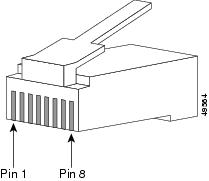
The alarm cables attach to the front of the 15310-CL using an RJ-45 connector that plugs into the ALARM port. The other end of the cable plugs into the alarm-collection equipment. Terminate this end of the cable according to local site practice.
The pins on the ALARM port correspond to the three external alarm inputs and the two external alarm outputs (controls) that you can define using Cisco Transport Controller (CTC). Table 1-1 lists the input alarm pinouts and the corresponding alarm function numbers assigned to each port.
Figure 1-4 shows RJ-45 pin numbering.
Figure 1-4 Pins 1 and 8 on the RJ-45 Connector
For more information about external alarms and controls, see the "10.6 External Alarms and Controls" section on page 10-13.
1.4.6 BITS Cable Installation
The building integrated timing supply (BITS) cables attach to the ONS 15310-CL using BITS clock cable and twisted-pair #22 or #24 unshielded AWG wire terminated with an RJ-45 connector that plugs into the BITS port. The other end of the cable plugs into the BITS clock. Terminate this end of the cable according to local site practice.
The 15310-CL has one BITS input and one BITS output. The BITS inputs and outputs have corresponding pins on the RJ-45 BITS ports. When connecting BITS cable to the ONS 15310-CL, see Table 1-2 for the BITS cable pin assignments.
For more information about connecting BITS timing to the ONS 15310-CL, refer to Chapter 6, "Timing.".
Table 1-2 BITS Cable Pin Assignments
1
BITS Output+
2
BITS Output-
3
BITS Input+
4
—
5
—
6
BITS Input-
7
—
8
—
Note
1.4.7 UDC Cable Installation
The 64K/RS-232 user data channel (UDC) interface provides E1, E2, F1, and F2 byte input and output. When connecting UDC cable to the ONS 15310-CL, see Table 1-3 for the UDC cable pin assignments. Shielded Twisted-pair (STP) #22 or #24 AWG wire is required for the UDC ports.
Table 1-3 UDC Cable Pin Assignments
1
NC
TX+
2
DTR
TX-
3
TXD
RX+
4
GND
GND
5
GND
GND
6
RXC
RX-
7
NC
NC
8
NC
NC
.
1.5 Fans
The ONS 15310-CL has five fans permanently mounted to the inside of the chassis. The fans are not removable.
1.6 Cards and Slots
Caution
The ONS 15310-CL provides one expansion slot that can accommodate one of two Ethernet cards, the CE-100T-8 card or the ML-100T-8 card. These cards have electrical plugs at the back that plug into electrical connectors on the shelf assembly backplane. When the ejectors are fully closed, the card plugs into the assembly backplane. Refer to Chapter 2, "Card Reference" for more information about ONS 15310-CL cards.
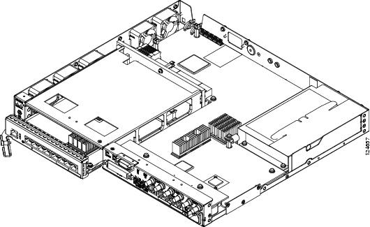
Figure 1-5 shows card installation for the ONS 15310-CL.
Figure 1-5 Installing an Ethernet Card
Note
Table 1-4 lists the number of ports, line rates, connector options, and connector locations for ONS 15310-CL electrical, Ethernet, and optical interfaces.