Table Of Contents
2.2 15310-CL-CTX Card Description
2.2.2 Synchronization and Timing
2.2.5 Communication and Control
2.2.6 Electrical Interface (BBE and WBE)
2.2.7 15310-CL-CTX Card-Level Indicators
2.3.1 CE-100T-8 Card-Level Indicators
2.3.2 CE-100T-8 Port-Level Indicators
2.4.1 ML100T-8 Card Description
2.4.2 ML100T-8 Card-Level Indicators
2.4.3 ML100T-8 Port-Level Indicators
Card Reference
This chapter describes the Cisco ONS 15310-CL cards. It includes descriptions, hardware specifications, and block diagrams for each card. For installation and turn-up procedures, refer to the Cisco ONS 15310-CL Procedure Guide.
Chapter topics include:
•
15310-CL-CTX Card Description
Note
2.1 Overview
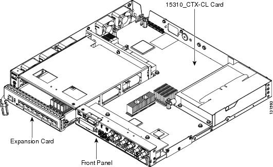
The Cisco ONS 15310-CL uses a common control card (the 15310-CL-CTX), an interconnect card, a connector expansion card, and a single expansion card (either the CE-100T-8 or ML100T-8). This overview provides a summary of the 15310-CL-CTX, CE-100T-8, and ML100T-8 cards. Figure 2-1 shows the ONS 15310-CL with an expansion card being inserted.
Figure 2-1 ONS 15310-CL with Expansion Card Being Inserted
2.1.1 Card Summary
Table 2-1 ONS 15310-CL Cards and Descriptions
The 15310-CL-CTX card serves as the common control and central element for ONS 15310-CL switching.
The CE-100T-8 card provides eight RJ-45 10/100-Mbps Ethernet ports.
See the "CE-100T-8 Card" section.
The ML100T-8 Ethernet card provides eight ports of 10/100 Ethernet-encapsulated traffic into SONET/SDH STS-3/STM-1 payloads.
See the "ML100T-8 Card" section.
The filler card is used to fill unused traffic card slots in the ONS 15310-CL shelf. The Cisco Transport Controller (CTC) GUI detects the filler card.
See the "Filler Card" section
The small form-factor pluggables (SFPs) are integrated fiber-optic transceivers that provide high-speed serial links from a port or slot to the network.
See the "SFP Modules" section
2.1.2 Card Compatibility
This section lists ONS 15310-CL cards and their compatible software versions. Table 2-2 lists Cisco Transport Controller (CTC) software release compatibility for each card. In the table, "Yes" means that the cards are compatible with the listed software versions. Table cells with dashes mean that the cards are not compatible with the listed software versions.
Table 2-2 ONS 15310-CL Software Release Compatibility Per Card
Yes
Yes
Yes
Yes
Yes
Yes
Yes
Yes
Yes
Yes
.
2.2 15310-CL-CTX Card Description
This section describes the features and functions of the ONS 15310-CL Common Control, Timing, Cross-Connect Customer-Located (15310-CL-CTX) card.
The 15310-CL-CTX card is an internal, nonremovable card residing in the ONS 15310-CL platform. It operates in a nonredundant configuration and performs system initialization, provisioning, alarm reporting, maintenance, diagnostics, IP address detection/resolution, SONET data communications channel (DCC) termination, system fault detection, and cross-connect maintenance and management for the ONS 15310-CL. The cards also provides the circuitry for the DS-1, DS-3/EC-1, and OC-3/OC-12 interfaces and ensures that the system maintains timing with SMC stability.
The 15310-CL-CTX card connects to an expansion card (CE-100T-8 or ML100T-8) through a mechanical interconnect card within the ONS 15310-CL chassis that is similar to a backplane in appearance. The ONS 15310-CL provides a front chassis opening that accepts either a blank card, a CE-100T-8 plug-in card, or an ML100T-8 plug-in card. When a card is plugged in, it connects to the 15310-CL-CTX card through the interconnect card.
The 15310-CL-CTX has three sets of ports:
•
•
•
Note
There are 21 WBE ports. They are automatically provisioned as DS-1 ports and cannot be deleted or changed. These ports are available at the LFH 96-pin connector on the ONS 15310-CL front panel.
There are three BBE ports. The BBE ports are automatically provisioned as DS-3 ports through the use of network element (NE) defaults. They can also be configured as EC-1 ports. Port creation and deletion is supported for the BBE ports. BBE port provisioning, configuration, creation, and deletion is accomplished through CTC. These ports are located on the ONS 15310-CL front panel.
There are two PPM (SFP) slots. Each slot can contain a one-port PPM. ONS 15310-CL PPMs can be single-rate (OC-3 or OC-12) or multirate (OC-3 and OC-12). Single-rate PPMs are autoprovisioned when they are installed, but multirate PPMs must be provisioned. This behavior can be controlled by NE defaults.
Note
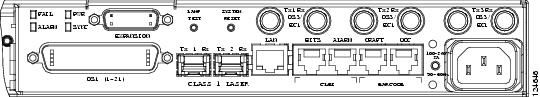
The 15310-CL-CTX card does not have a faceplate because it is located inside the chassis; however, the 15310-CL-CTX LED indicators and connectors are located on the ONS 15310-CL front panel (Figure 2-2).
Figure 2-2 ONS 15310-CL Front Panel
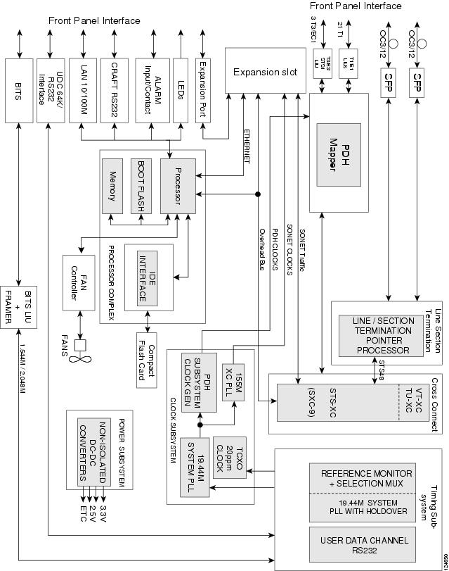
Figure 2-3 shows the 15310-CL-CTX card functional block diagram.
Figure 2-3 15310-CL-CTX Block Diagram
2.2.1 Features
The 15310-CL-CTX card has the following features:
•
•
•
•
•
•
•
•
•
•
•
•
•
2.2.2 Synchronization and Timing
This synchronization and timing subsystem is responsible for monitoring and selecting reference clocks in the node. A free-running SMC clock, accurate to 20 ppm, is available for internal synchronization in the event that no synchronization timing source is available. The 15310-CL-CTX card is normally synchronized from the optical link.
2.2.3 System Cross-Connect
This subsystem is responsible for the setup and maintenance of cross-connections within the system. It supports STS-Nc, STS-1, and VT1.5 cross-connect capability in SONET mode.
2.2.4 Optical Interface
The optical subsystem provides two SFP optical transceivers for two OC-3/OC-12 SONET-compliant interfaces.
2.2.5 Communication and Control
This subsystem is responsible for overall control of the system, such as system initialization, provisioning, alarm reporting, maintenance, diagnostics, intercard communication, DCC termination, and system fault detection.
2.2.6 Electrical Interface (BBE and WBE)
This subsystem supports Telcordia GR-499 compliant, 1.544-Mbps (DS-1) and 44.736-Mbps (DS-3/EC-1) interfaces. Performance monitoring is provided by means of this interface to allow validation of signal quality.
Any outgoing DS-1 signal can be retimed to eliminate accumulated jitter and wander at the point of egress from a synchronous network. Any incoming DS-1 signal from the transport element can also be used as timing source.
2.2.7 15310-CL-CTX Card-Level Indicators
The 15310-CL-CTX card is responsible for operating the LED indicators on the ONS 15310-CL front panel. The panel has four card-level LEDs, described in Table 2-3.
2.3 CE-100T-8 Card
This section describes the features and functions of the ONS 15310-CL 10/100 Ethernet (CE-100T-8) card.
The CE-100T-8 card maps 8-port 10/100-Mbps Ethernet-encapsulated traffic into SONET payloads, making use of low-order (VT1.5) virtual concatenation (VCAT), high-order (STS-1, STS-3c) VCAT, generic framing procedure (GFP), and Point-to-Point Protocol/high-level data link control (PPP/HDLC) framing protocols. It also supports the link capacity adjustment scheme (LCAS), which allows hitless dynamic adjustment of SONET link bandwidth. The CE-100T-8 card provides eight RJ-45 10/100-Mbps Ethernet ports on the faceplate of the card. An inactive RJ-45 console port is also on the faceplate.
The circuit types supported are:
•
•
•
•
•
•
Each 10/100 Ethernet port can be mapped to a SONET channel in increments of VT1.5 or STS-1 granularity. There are eight backend packet-over-SONET (POS) ports (VCAT groups [VCGs]) available on the ML100T-8 card. Additionally, the CE-100T-8 card supports packet processing, classification, quality of service (QoS)-based queuing, and traffic scheduling.
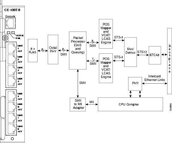
Figure 2-4 shows the CE-100T-8 card faceplate and block diagram.
Figure 2-4 CE-100T-8 Faceplate and Block Diagram
The following paragraphs describe the general functions of the CE-100T-8 card and relate it to the block diagram.
In the ingress direction (Ethernet-to-SONET), an octal PHY, which performs all of the physical layer interface functions for 10/100-Mbps Ethernet, sends the frame to the Packet Processor for queuing in the respective packet buffer memory. The Packet Processor performs packet processing, packet switching, and classification. The Ethernet frames are then passed over SMII channels to the POS Mappers, where Ethernet traffic is terminated and is encapsulated using the PPP/HDLC or GFP framing protocols. The encapsulation method is selected on a per-port basis. The encapsulated Ethernet frames are then mapped into a configurable number of VCAT low-order and high-order payloads, such as VT1.5 synchronous payload envelope (SPE), STS-1 SPE, or a contiguous concatenated (CCAT) payload such as STS-3c SPE. Up to 64 VT1.5 SPEs or three STS-1 SPEs can be virtually concatenated.
The SPE from each POS Mapper (up to STS-3) carrying encapsulated Ethernet frames are passed onto the multiplexer/demultiplexer (Mux/Demux) next, where the STS-3 frames from both POS Mappers are multiplexed to form an STS-12 frame for transport over the SONET network by means of the Bridging Transmission Convergence (BTC-48) ASIC.
Note
In the egress direction (SONET-to-Ethernet), the Mux/Demux extracts the first and second STS-3 SPEs from the STS-12 frame it receives from the BTC-48 before sending them to the POS Mappers. The STS-3 SONET SPE carrying GFP or PPP/HDLC encapsulated Ethernet frames are then extracted and buffered in the external memory of the POS Mappers. This memory is used for providing alignment and differential delay compensation for the received low/high order virtual concatenated payloads. When alignment and delay compensation are complete, the Ethernet frames are decapsulated with one of the framing protocols (GFP or PPP/HDLC). Decapsulated Ethernet frames are then passed onto the Packet Processor for quality-of-service (QoS) queuing and traffic scheduling. The Network Processor switches the frame to one of the corresponding PHY channels and then onto the Ethernet port for transmission to the external clients.
With regard to QoS, users can use the VLAN class-of-service (CoS) threshold (value 0 to 7, default 7) of incoming Ethernet packets and the IP type-of-service (ToS) threshold (value 0 to 255, default 255) of incoming Ethernet packets for priority queuing. These thresholds are provisionable through CTC, TL1, and Cisco Transport Manager (CTM). CoS takes precedence over ToS unless the CoS threshold is set to the default of 7. This threshold value does not prioritize any packets based on CoS, so ToS is used. The value configured is a threshold and any value greater than that value is set as a priority. For example, if a CoS of 5 is set as the threshold, only CoS values of 6 and 7 would be set to priority.
2.3.1 CE-100T-8 Card-Level Indicators
The CE-100T-8 card faceplate has two card-level LED indicators, described in Table 2-4.
2.3.2 CE-100T-8 Port-Level Indicators
The CE-100T-8 card has two LEDs embedded into each of the eight Ethernet-port RJ-45 connectors. The LEDs are described in Table 2-5.
2.4 ML100T-8 Card
This section describes the features and functions of the ONS 15310-CL Multilayer 10/100 Ethernet (ML100T-8) card.
2.4.1 ML100T-8 Card Description
The ML100T-8 card maps eight ports of 10/100 Ethernet encapsulated traffic into SONET STS-3 payloads. The card is compatible with high-order STS-1 VCAT and the GFP and PPP/HDLC framing protocols. It also supports LCAS, which allows hitless dynamic adjustment of SONET/SDH link bandwidth. Each 10/100 Ethernet port can be mapped to a SONET channel in increments of STS-1 granularity.
The ML100T-8 card provides a switched operating mode, with eight subscriber interfaces and two virtual POS (VCG) interfaces mapped through the cross-connect for transport with other services between NEs.
The circuit types supported are:
•
•
•
•
Additionally, the ML100T-8 card supports packet processing, classification, QoS-based queuing, traffic scheduling, and packet multiplexing services for Layer2/3. The ML100T-8 card facilitates more efficient transport of Ethernet and IP over the SONET/SDH infrastructure with multilayer intelligence.
The ML100T-8 contains an RJ-45 console port that is active by default. It is used to receive keyboard input as well as output error and warning messages.
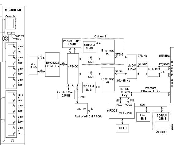
Figure 2-5 shows the ML100T-8 card faceplate and block diagram.
Figure 2-5 ML100T-8 Card Faceplate and Block Diagram
The following paragraphs describe the general functions of the ML100T-8 card and relate to the block diagram.
In the ingress direction (Ethernet-to-SONET), Ethernet frames first enter from a physical Ethernet port to one of the corresponding channels of the octal PHY, which performs all of the physical layer interface functions for 10/100 Ethernet. The PHY sends the Ethernet frame to the Packet Processor by means of the SMII interfaces for queuing in the respective packet buffer memory. The Packet Processor performs packet processing, packet switching, and classification. The Ethernet frames are then passed on to the POS Mappers through the SMII interfaces. The POS Mappers terminate the 10/100-Mbps Ethernet traffic. The Ethernet frames are extracted and buffered in POS Mapper external memory. Ethernet frames are encapsulated using one of the framing protocols (PPP/HDLC or GFP), selected on a per-port basis. The encapsulated Ethernet frames are mapped into a configurable number of STS-1 or VCAT high-order payloads (STS-1-1v or STS-1-2v). The SPE from each POS Mapper (up to STS-3) carrying encapsulated Ethernet frames are next passed onto the Mux/Demux, where the STS-3 frames from both POS Mappers are multiplexed to form an STS-12 frame for transport over the SONET network by means of the BTC-48 ASIC.
Note
In the egress direction (SONET-to-Ethernet), the Mux/Demux extracts the first and second STS-3 SPEs from the STS-12 frame it receives from the BTC-48 before sending it to the POS Mapper. The STS-3 SONET SPEs carrying GFP or PPP/HDLC encapsulated Ethernet frames are then extracted and buffered in the POS Mapper external memory. This memory is used for providing alignment and differential delay compensation for the received high-order VCAT payloads. After alignment and delay compensation have been done, the Ethernet frames are decapsulated with one of the framing protocols (GFP or PPP/HDLC). Decapsulated Ethernet frames are then passed onto the Network Processor for QoS queuing, traffic scheduling, packet switching, and multiplexing. The Network Processor switches the frame to one of the corresponding PHY channels and then onto the Ethernet port for transmission to the external clients.
2.4.2 ML100T-8 Card-Level Indicators
The ML100T-8 card faceplate has two card-level LED indicators, described in Table 2-6.
2.4.3 ML100T-8 Port-Level Indicators
The ML100T-8 card has two LEDs embedded into each of the eight Ethernet port RJ-45 connectors. The LEDs are described in Table 2-7.
2.5 Filler Card
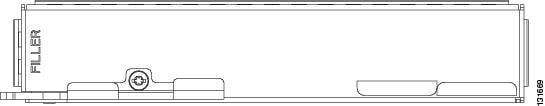
If an expansion card (CE-100T-8 or ML100T-8) is not plugged in, a filler card must be inserted in the expansion slot. The filler card serves three functions: it prevents exposure to hazardous voltages and currents inside the ONS 15310-CL chassis, it eliminates electromagnetic interference (EMI) that might disrupt other equipment, and it directs the flow of cooling air through the chassis.
Caution
The blank card is a printed circuit board (PCB) with a blank faceplate and two connectors that, when the card is installed, plug into receptacles at the back of the slot. CTC, the ONS 15310-CL graphical user interface (GUI), detects when a filler car d is plugged in and displays it in node view.
Figure 2-6 shows the filler card faceplate.
Figure 2-6 Filler Card
2.6 SFP Modules
This section describes the SFPs that can be used with the 15310-CL-CTX card. The 15310-CL-CTX card does not have a faceplate because it is located inside the chassis; therefore, the two SFP slots are located on the ONS 15310-CL faceplate, just to the left of the LAN connector (see Figure 2-2). The CE-100T-8 and ML100T-8 cards do not use SFPs.
2.6.1 Compatibility by Card
Table 2-8 lists the SFPs compatible with the 15310-CL-CTX card.
Caution
2.6.2 SFP Description
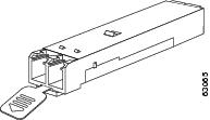
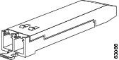
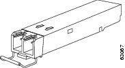
SFPs are integrated fiber-optic transceivers that provide high-speed serial links from a port or slot to the network. Various latching mechanisms can be utilized on the SFPs. There is no correlation between the type of latch to the model type (such as SX or LX/LH) or technology type (such as Gigabit Ethernet). See the label on the SFP for the technology type and model. One type of latch available is a mylar tab, shown in Figure 2-7. A second type of latch is an actuator/button (Figure 2-8), and a third type is a bail clasp (Figure 2-9).
SFP dimensions are:
•
•
•
SFP temperature ranges are:
•
•
•
Figure 2-7 Mylar Tab SFP
Figure 2-8 Actuator/Button SFP
Figure 2-9 Bail Clasp SFP
2.6.3 PPM Provisioning
SFPs are known as pluggable-port modules (PPMs) in the ONS 15310-CL graphical user interface (GUI), CTC. SFPs for the 15310-CL-CTX card can be provisioned for different line rates in CTC. See the "15310-CL-CTX Card Description" section for more information. For procedures for provisioning PPMs, refer to the Cisco ONS 15310-CL Procedure Guide.