Downloads |
 Feedback Feedback
|
Table Of Contents
2.1.3 Mechanical Interface Cards
2.2 XTC Cards (XTC-28-3/XTC-14)
2.2.3 Support for DS-1 and DS-3
2.2.4 XTC Timing and Control Functionality
2.2.5 XTC Cross-Connect Functionality
2.3 Mechanical Interface Cards
2.3.5 External Alarms and Controls
2.4.1 OC3 IR 4 1310 Card Description
2.4.2 OC3 IR 4 1310 Card-Level Indicators
2.5.1 OC12 IR 1310 Card Description
2.5.2 OC12 IR 1310 Card-Level Indicators
2.6.1 OC12 LR 1550 Card Description
2.6.2 OC12 LR 1550 Card-Level Indicators
2.7.1 OC48-1-IR Card Description
2.7.2 OC48-1-IR Card-Level Indicators
2.8.1 OC48 LR 1550 Card Description
2.8.2 OC48 LR 1550 Card-Level Indicators
2.9.1 E10/100-4 Card Description
2.9.2 E10/100-4 Card-Level Indicators
2.9.3 E10/100-4 Port-Level Indicators
2.10.1 G1000-2 Card Description
2.10.3 G1000-2 Card-Level Indicators
2.10.4 G1000-2 Port-Level Indicators
Card Reference
Note
The terms "Unidirectional Path Switched Ring" and "UPSR" may appear in Cisco literature. These terms do not refer to using Cisco ONS 15xxx products in a unidirectional path switched ring configuration. Rather, these terms, as well as "Path Protected Mesh Network" and "PPMN," refer generally to Cisco's path protection feature, which may be used in any topological network configuration. Cisco does not recommend using its path protection feature in any particular topological network configuration.
This chapter describes the Cisco ONS 15327 cards. It includes descriptions, hardware specifications, and block diagrams for each card. For installation and turn-up procedures, refer to the Cisco ONS 15327 Procedure Guide.
Chapter topics include:
Note
2.1 Overview
The Cisco ONS 15327 uses common control cards, mechanical interface cards, optical cards, an Ethernet/Fast Ethernet card, and a Gigabit Ethernet card. This overview provides a summary of the cards. Figure 2-1 shows the ONS 15327 slot assignments.
Figure 2-1 ONS 15327 Slot Assignments
2.1.1 Card Compatibility
This section lists ONS 15327 cards and their compatible software versions. In the table below, "Yes" means the cards are compatible with the listed software version. Table cells with dashes mean cards are not compatible with the listed software versions.
Table 2-1 lists Cisco Transport Controller (CTC) software release compatibility for each card.
2.1.2 Common Control Cards
The two common control cards are the Cross-Connect, Timing, and Control (XTC-28-3 and XTC-14) cards. Both cards provide timing, control, and digital cross-connect functions. They also provide the EIA/TIA-232 DB9 TL1 connection and RJ-45 LAN connection. The XTC-28-3 provides electrical-tributary circuitry for 28 DS-1s and three DS-3s. The XTC-14 provides electrical-tributary circuitry for 14 DS-1s.
2.1.3 Mechanical Interface Cards
The mechanical interface cards (MICs) provide the physical connection points for the DS-1 and DS-3 interfaces on the XTC cards, the redundant power inputs, the alarm inputs and outputs, and the building integrated timing supply (BITS) inputs and outputs.
2.1.4 Optical Cards
The ONS 15327 optical cards include:
•
•
•
•
•
2.1.5 E10/100-4 Ethernet Card
The Ethernet card provides four Layer 2 switched, autosensing, 10/100BaseT Ethernet interfaces. Each interface supports full-duplex operation for a maximum bandwidth of 200 Mbps per port.
2.1.6 Gigabit Ethernet Card
The Gigabit Ethernet card provides two 1000-Mbps Gigabit Ethernet interfaces. Each interface supports full-duplex operation for a maximum bandwidth of 2000 Mbps per port.
2.2 XTC Cards (XTC-28-3/XTC-14)
This section describes the features and functions of the XTC cards.
2.2.1 XTC Card Overview
The XTC cards perform system initialization, provisioning, alarm reporting, maintenance, diagnostics, IP address detection and resolution, SONET data communication channel (DCC) termination, system fault detection, and cross-connect maintenance and management for the ONS 15327. The XTC cards also provide the circuitry for the DS-1 and DS-3 interfaces and ensure that the system maintains Telcordia timing requirements.
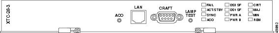
An XTC card is required to operate the ONS 15327 and can be used in a redundant or nonredundant configuration. Figure 2-2 shows the XTC-28-3 faceplate.
Note
Figure 2-2 XTC-28-3 Card Faceplate
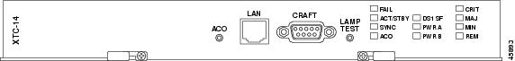
Figure 2-3 shows the XTC-14 faceplate.
Figure 2-3 XTC-14 Card Faceplate
2.2.2 XTC Front Panel
The XTC cards have an alarm cutoff (ACO) button, an RJ-45 LAN port, an EIA/TIA-232 TL1 (CRAFT) interface port, and a LAMP TEST button. The XTC-28-3 front panel has 12 LEDs, and the XTC-14 front panel has 11 LEDs. The following list describes each LED:
•
•
•
•
•
•
•
•
•
•
•
2.2.3 Support for DS-1 and DS-3
The XTC cards contain the circuitry for connecting DS-1s. The XTC-28-3 also contains the circuitry for connecting DS-3s. The XTC-28-3 supports 28 DS-1s and 3 DS-3s. The XTC-14 supports 14 DS-1s. The DS-1 circuitry on the XTC cards maps each of the received DS-1 signals into VT 1.5s and concatenates these virtual tributaries (VTs) into one STS-1. Full VT1.5 grooming is supported.
The physical connection points are located on the MIC. See the "MIC Overview" section for more information about physical connections.
2.2.4 XTC Timing and Control Functionality
The XTC cards combine the timing and control functions into one card. You can install the XTC cards in one or both of the common control slots (Slots 5 and 6). XTC cards must be installed in both of the common control slots for redundancy. In a nonredundant configuration, you must install the XTC in Slot 6.
The XTC cards support multichannel, high-level data link control (HDLC) processing for the DCC. Up to four DCCs can be routed over the serial communication interface (SCI) and terminated at the XTC card. The XTC cards process ten DCCs to enable remote system management interfaces.
Note
The node database, IP address, and system software are stored in XTC card nonvolatile memory, which allows quick recovery in the event of a power or card failure.
The XTC cards perform all system-timing functions for each ONS 15327. The XTC cards select a recovered clock from optical line cards, a BITS, or an internal Stratum 3 reference as the system-timing reference. You can provision any of the clock inputs as a primary or secondary timing source. A slow-reference tracking loop allows the XTC cards to synchronize to the recovered clock, which provides holdover if the reference is lost.
In a redundant configuration, if the working XTC card fails, traffic switches to the protect XTC card. All XTC protection switches conform to protection switching standards when the bit error rate (BER) counts are not in excess of 1 E-3 and completion time is less than 50 ms.
The XTC cards feature an RJ-45 10BaseT LAN port and an EIA/TIA-232 DB9 type craft interface for user interfaces. The craft port runs at 9600 bps.
2.2.5 XTC Cross-Connect Functionality
The XTC card is the central element for ONS 15327 switching. It establishes cross connections and performs time-division switching (TDS) at the STS-1 and VT 1.5 level between ONS 15327 traffic cards.
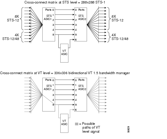
The switch matrix on the XTC card consists of 288 bidirectional ports. When creating bidirectional STS-1 cross-connects, each cross-connect uses two STS-1 ports. This results in 144 bidirectional STS-1 cross-connects. The switch matrix is nonblocking and broadcast supporting. This allows network operators to concentrate or groom low-speed traffic from line cards onto high-speed transport spans and to drop low-speed traffic from transport spans onto line cards. Figure 2-4 shows the cross-connect matrix for the XTC card.
Figure 2-4 Cross-Connect Matrix
The XTC card supports a total of 672 cross-connects with a payload granularity of VT 1.5. The VT functionality supports ring configurations with a mix of VT-capable Cisco transport network elements (NEs) and STS-only capable Cisco transport NEs.
The XTC card provides protection switching control for external and internal VT paths. The card also performs path- and STS-level monitoring and protection switching.
2.2.6 VT Mapping
The Cisco ONS 15327 performs VT mapping according to Telcordia GR-253 standards. Table 2-2 shows the VT numbering scheme for the ONS 15327 as it relates to the Telcordia standard.
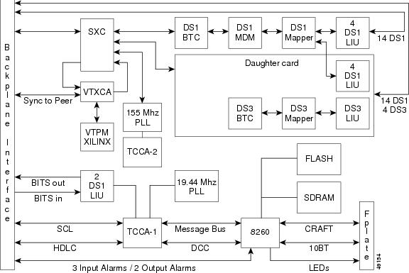
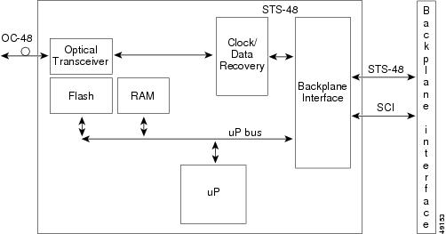
Figure 2-5 shows the block diagram for the XTC card.
Figure 2-5 XTC Block Diagram
2.3 Mechanical Interface Cards
This section describes the features and functions of the MICs.
2.3.1 MIC Overview
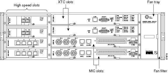
Two MICs (MIC A and MIC B) are required to operate the Cisco ONS 15327 when using XTC-28-3 cards or when redundant power inputs are needed. The MICs provide power connection points, physical interfaces for DS-1s and DS-3s, and external timing and alarm interfaces.
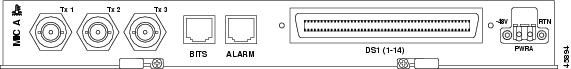
Figure 2-6 shows the MIC A faceplate. MIC A is keyed so that it can only be installed in Slot 8.
Figure 2-6 MIC A Faceplate
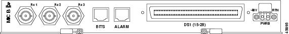
Figure 2-7 shows the MIC-28-3-B faceplate. MIC-B is keyed so that it can only be installed in Slot 7.
Figure 2-7 MIC B Faceplate
2.3.2 DS-1 Physical Interface
Each MIC uses a 64-pin Champ connector to provide 14 DS-1 interfaces. MIC-28-3-A provides connection to DS-1s 1 to 14, and MIC-28-3-B provides connection to DS-1s 15 to 28. The XTC cards house the electrical tributary circuitry for managing the individual DS-1s.
2.3.3 DS-3 Physical Interface
Because the transmit (out) and receive (in) interfaces are on different cards, you must install both MICs to use the DS-3 capabilities of the ONS 15327. The DS-3 interfaces use BNC connectors. MIC-28-3-A provides the three transmit (Tx) interfaces and MIC-28-3-B provides the three receive (Rx) interfaces. The XTC-28-3 card houses the electrical-tributary circuitry for managing DS-3s.
2.3.4 Power Connection
Each MIC has one -48 VDC power terminal that uses spring terminal block connectors and accepts #12 to #16 AWG wire (the National Electrical Code [NEC] requires #12 to #14 AWG wire). To establish redundant power, install both MICs and connect each one to a power source.
2.3.5 External Alarms and Controls
Each MIC has three Form C discrete external alarm inputs and one Form C discrete external control. Connection to the external alarms and controls uses an RJ-45 connector. Two wires of the RJ-45 connector are used for the external control, which defaults to the open position. Six wires of the RJ-45 connector are used for the external alarm input.
In CTC, you can provision the six external alarm inputs (three on each MIC) and the two external controls (one on each MIC). External alarm inputs are typically used for external sensors such as open doors, temperature sensors, flood sensors, and other environmental conditions. They can be set to Alarm on Closure or Alarm on Open. The alarm severity can be set to any of five available levels (Critical, Major, Minor, Not Alarmed, Not Reported). In addition to severity, you can set alarm type and virtual wire for alarm contacts 1 to 4 and define when the alarm is raised. You can assign a 63-character alarm description for display in the alarm log of the CTC. The alarm condition remains raised until the external input quits driving the contact and you clear the alarm in the CTC. For instructions, refer to the Cisco ONS 15327 Procedure Guide.
External controls are typically used to drive visual or audible devices such as bells and lights, but they can control other devices such as generators, heaters, and fans. You can set them to close when the specified alarm condition is triggered; the default condition for output alarms is the open position. The alarm triggering conditions can be any ONS 15327 alarm condition including the user-defined input alarms, severity-based alarms (for example, trigger when any major alarm occurs), or remote alarms. CTC provisioning of this alarm-to-output-contact association is menu driven and includes alarms and individual alarms within categories. The output contact electrical interface is 50 V, 100 mA. To provision external controls, refer to the Cisco ONS 15327 Procedure Guide.
2.3.6 BITS Interface
Each MIC provides connection for one BITS clock input and one BITS clock output using an RJ-45 connector. Each MIC uses two wires of the RJ-45 connector.
2.4 OC3 IR 4 1310 Card
This section describes the features and functions of the OC3 IR 4 1310 card. For card provisioning, such as changing line and threshold settings, refer to the Cisco ONS 15327 Procedure Guide.
2.4.1 OC3 IR 4 1310 Card Description
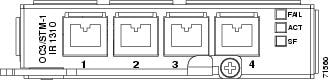
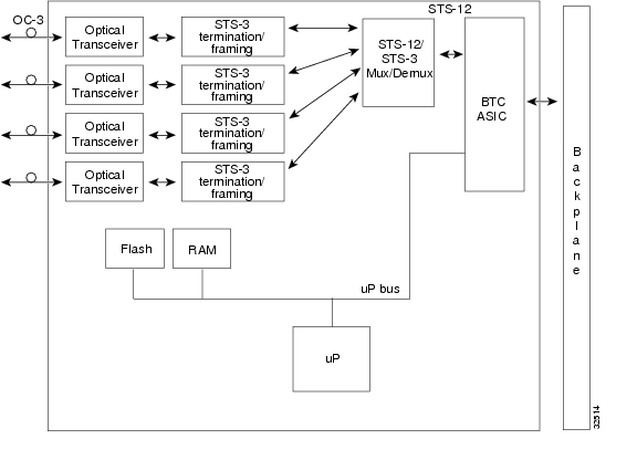
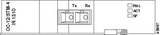
The OC3 IR 4 1310 card provides four intermediate-reach, Telcordia-compliant, GR-253 SONET OC-3 interfaces per card. The interface operates at 155.52 Mbps over a single-mode fiber span and supports VT payloads and nonconcatenated or concatenated payloads for STS-1 or STS-3c. Figure 2-8 shows the OC3 IR 4 1310 faceplate.
Figure 2-8 OC3 IR 4 1310 Card Faceplate
You can install the OC3 IR 4 1310 card in any ONS 15327 high-speed card slot. The card can be provisioned as part of a path protection or a linear add-drop multiplexer (ADM) configuration.The card does not support bidirectional line-switched rings (BLSR). Each port features a 1310 nm laser and contains a transmit and receive connector on the card faceplate (the left-hand connector is the transmit [Tx] port and the right-hand connector is the receive [Rx] port). The card uses LC connectors.
The OC3 IR 4 1310 card supports 1+1 unidirectional or bidirectional protection switching. You can provision protection on a per-port basis. See the "Optical Card Protection" section for more information.
The OC3 IR 4 1310 detects loss of signal (LOS), loss of frame (LOF), loss of pointer (LOP), alarm indication signal-line (AIS-L), and line remote defect indication (RDI-L) conditions. Refer to the Cisco ONS 15327 Troubleshooting Guide for a description of these conditions. The card also counts section and line bit interleaved parity (BIP) errors.
2.4.2 OC3 IR 4 1310 Card-Level Indicators
Table 2-3 describes the three card-level LED indicators on the OC3 IR 4 1310 card.
Figure 2-9 shows the OC3 IR 4 1310 card block diagram.
Figure 2-9 OC3 IR 4 1310 Card Block Diagram
2.5 OC12 IR 1310 Card
This section describes the features and functions of the OC12 IR 1310 card. For card provisioning, refer to the Cisco ONS 15327 Procedure Guide.
2.5.1 OC12 IR 1310 Card Description
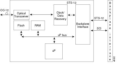
The OC12 IR 1310 card provides one intermediate- or short-reach, SONET OC-12 interface per card, compliant with Telcordia GR-253. The interface operates at 622.08 Mbps over a single-mode fiber span and supports VT payloads and nonconcatenated or concatenated payloads for STS-1, STS-3c, STS-6c, or STS-12c. Figure 2-10 shows the OC12 IR 1310 faceplate.
Figure 2-10 OC12 IR 1310 Card Faceplate
Figure 2-11 shows the OC12 IR 1310 card block diagram.
Figure 2-11 OC12 IR 1310 Card Block Diagram
You can install the OC12 IR 1310 card in any ONS 15327 high-speed slot and provision the card as a drop card or span (trunk) card in a two-fiber BLSR, path protection, or ADM (linear) configuration.
The OC12 IR 1310 port features a 1310-nm laser and contains a transmit and receive connector (labeled) on the card faceplate. The OC12 IR 1310 card uses SC optical connections and supports 1+1 unidirectional and bidirectional protection.
The OC12 IR 1310 detects LOS, LOF, LOP, AIS-L, and RDI-L conditions. Refer to the Cisco ONS 15327 Troubleshooting Guide for a description of these conditions. The card counts section and line BIT errors.
2.5.2 OC12 IR 1310 Card-Level Indicators
Table 2-4 describes the three card-level LED indicators on the OC12 IR 1310 card.
2.6 OC12 LR 1550 Card
This section describes the features and functions of the OC12 LR 1550 card. For card provisioning, refer to the Cisco ONS 15327 Procedure Guide.
2.6.1 OC12 LR 1550 Card Description
The OC12 LR 1550 card provides one long-reach, Telcordia-compliant, GR-253 SONET OC-12 interface per card. The interface operates at 622.08 Mbps over a single-mode fiber span and supports VT payloads and nonconcatenated or concatenated payloads for STS-1, STS-3c, STS-6c, or STS-12c. Figure 2-12 shows the OC12 LR 1550 faceplate.
Figure 2-12 OC12 LR 1550 Card Faceplate
Figure 2-13 shows the OC12 LR 1550 card block diagram.
Figure 2-13 OC12 LR 1550 Card Block Diagram
You can install the OC12 LR 1550 card in any ONS 15327 high-speed card slot and provision the card as a drop card or span (trunk) card in a BLSR, path protection, or ADM (linear) configurations.
The OC-12 interface features a 1550-nm laser and contains a transmit (Tx) and receive (Rx) connector (labeled) on the card faceplate. The OC12 LR 1550 uses SC connectors. The OC12 LR 1550 card supports 1+1 unidirectional and bidirectional switching.
The OC12 LR 1550 detects LOS, LOF, and LOP, and AIS-L conditions (refer to the Cisco ONS 15327 Troubleshooting Guide for a complete description of alarm conditions). The OC12 LR 1550 counts path and line BIT errors.
The OC12 LR 1550 extracts the K1 and K2 bytes from the SONET overhead to perform an appropriate protection switch. The DCC bytes are forwarded to the DCC-terminating XTC.
2.6.2 OC12 LR 1550 Card-Level Indicators
Table 2-5 describes the three card-level LED indicators on the OC12 LR 1550 card.
2.7 OC48-1-IR Card
This section describes the features and functions of the OC48-1-IR card. For card provisioning, refer to the Cisco ONS 15327 Procedure Guide.
2.7.1 OC48-1-IR Card Description
The OC48-1-IR card provides one intermediate-reach, Telcordia-compliant, GR-253 SONET OC-48 interface per card. Each interface operates at 2488.320 Mbps over a single-mode fiber span and supports VT payloads and nonconcatenated or concatenated payloads for STS-1, STS-3c, STS-6c, STS-12c, or STS-48c. Figure 2-14 shows the OC48-1-IR faceplate.
Figure 2-14 OC48-1-IR Card Faceplate
Figure 2-15 shows the OC48-1-IR block diagram.
Figure 2-15 OC48-1-IR Block Diagram
You can install the OC48-1-IR card in any ONS 15327 high-speed card slot and provision the card as a drop or span (trunk) card in a two-fiber BLSR, path protection, or in an ADM (linear) configuration.
The OC-48 port features a 1310-nm laser and contains a transmit and receive connector (labeled) on the card faceplate. The OC48-1-IR uses SC connectors. The card supports 1+1 unidirectional and bidirectional protection switching.
The OC48-1-IR detects LOS, LOF, LOP, AIS-L, and RDI-L conditions. Refer to the Cisco ONS 15327 Troubleshooting Guide for a description of these conditions. The card also counts section and line BIT errors.
2.7.2 OC48-1-IR Card-Level Indicators
Table 2-6 describes the three card-level LED indicators on the OC48-1-IR card.
2.8 OC48 LR 1550 Card
This section describes the features and functions of the OC48 LR 1550 card. For card provisioning, refer to the Cisco ONS 15327 Procedure Guide.
2.8.1 OC48 LR 1550 Card Description
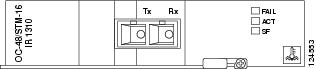
The OC48 LR 1550 card provides one intermediate-reach, Telcordia-compliant, GR-253 SONET OC-48 interface per card. Each interface operates at 2488.320 Mbps over a single-mode fiber span and supports VT payloads and nonconcatenated or concatenated payloads for STS-1, STS-3c, STS-6c, STS-12c, or STS-48c. Figure 2-16 shows the OC48 LR 1550 faceplate.
Figure 2-16 OC48 LR 1550 Card Faceplate
Figure 2-17 shows the OC48 LR 1550 block diagram.
Figure 2-17 OC48 LR 1550 Block Diagram
You can install the OC48 LR 1550 card in any ONS 15327 high-speed card slot and provision the card as a drop or span (trunk) card in a two-fiber BLSR, path protection, or ADM (linear) configuration.
The OC48 LR 1550 port features a 1550-nm laser and contains a transmit and receive connector (labeled) on the card faceplate. The card uses SC connectors, and it supports 1+1 unidirectional and bidirectional protection switching.
The OC48 LR 1550 detects LOS, LOF, LOP, AIS-L, and RDI-L conditions. Refer to the Cisco ONS 15327 Troubleshooting Guide for a description of these conditions. The card also counts section and line BIT errors.
2.8.2 OC48 LR 1550 Card-Level Indicators
Table 2-7 describes the three card-level LED indicators on the OC48 LR 1550 card.
2.9 E10/100-4 Card
This section describes the features and functions of the E10/100-4 card. For card provisioning, refer to the Cisco ONS 15327 Procedure Guide.
2.9.1 E10/100-4 Card Description
The E10/100-4 card provides four IEEE 802.3-compliant, 10/100 interfaces. Each interface supports full-duplex operation for a maximum bandwidth of 200 Mbps per port and 622 Mbps per card. Each port can independently detect (autosense) the speed of an attached device and automatically connects at the appropriate speed. The ports autoconfigure to operate at either half or full duplex and can determine whether to enable or disable flow control. You can manually set the port speed and duplex mode.
Figure 2-18 shows the card faceplate.
Figure 2-18 E10/100-4 Card Faceplate
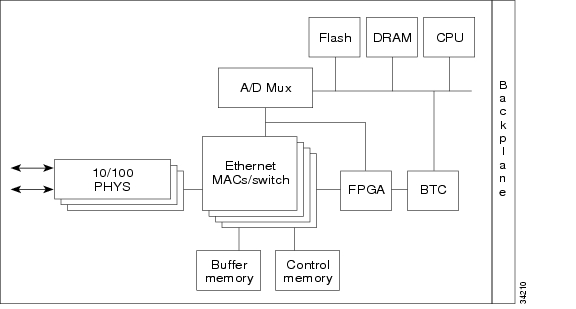
Figure 2-19 provides a block diagram of the E10/100-4 card.
Figure 2-19 E10/100-4 Block Diagram
The E10/100-4 Ethernet card provides high-throughput, low-latency packet switching of Ethernet traffic across a SONET network while providing a greater degree of reliability through SONET "self-healing" protection services. This Ethernet capability enables network operators to provide multiple 10/100 Mbps access drops for high-capacity customer LAN interconnects, Internet traffic, and cable modem traffic aggregation. Efficient transport and coexistence of traditional TDM traffic with packet-switched data traffic is provided.
Each E10/100-4 card supports standards-based, wire-speed, Layer 2 Ethernet switching between its Ethernet interfaces. IEEE 802.1Q-tag and port-based VLANs are supported in order to logically isolate traffic (typically subscribers). Priority queuing is also supported in order to provide multiple classes of service.
You can install the E10/100-4 card in any high-speed slot. Multiple Ethernet cards installed in an ONS 15327 can act as a single switch or multiple switches supporting a variety of SONET port configurations. To create logical SONET ports, provision a number of STS channels to the packet switch entity within the ADM. You can create logical ports with a bandwidth granularity of STS-1. The ONS 15327 can support six STS-1s, two STS-3cs, one STS-6c, or one STS-12c in single-card EtherSwitch mode. It supports three STS-1s or one STS-3c in multicard EtherSwitch mode.
2.9.2 E10/100-4 Card-Level Indicators
Table 2-8 describes the two card-level LED indicators The E10/100-4 card faceplate has three LEDs, described in Table 2-8.
2.9.3 E10/100-4 Port-Level Indicators
Table 2-9 describes the four pairs of LEDs (one pair for each port) on the E10/100-4 card that indicate status, such as signal or equipment failures.
Table 2-9 E10/100-4 Port-Level Indicators
Transmitting and receiving
Idle and link integrity
Inactive connection or unidirectional traffic
2.10 G1000-2 Card
This section describes the features and functions of the ONS 15327 Gigabit Ethernet card, called the G1000-2 card. For card provisioning, refer to the Cisco ONS 15327 Procedure Guide.
2.10.1 G1000-2 Card Description
The G1000-2 provides two IEEE 802.3-compliant, 1000 Mbps ports for high-capacity customer LAN interconnections. Each port supports full-duplex operation for a maximum bandwidth of 2000 Mbps per port or support of Gigabit Ethernet traffic at full line rate. The SONET circuit sizes supported are STS-1, STS-3c, STS-6c, STS-9c, STS-12c, STS-24c, and STS-48c.
Figure 2-20 shows the card faceplate.
Figure 2-20 G1000-2 Card Faceplate
The G1000-2 Gigabit Ethernet card provides high-throughput, low latency transport of Ethernet encapsulated traffic (IP and other Layer 2 or Layer 3 protocols) across a SONET network. Carrier-class Ethernet transport is achieved by hitless (< 50 ms) performance in the event of any failures or protection switches (such as 1+1 APS, path protection, or BLSR) and software upgrades. Full provisioning support is possible via CTC, TL1, or CTM (refer to the Cisco ONS 15454 and Cisco ONS 15327 TL1 Command Guide for G-Series TL1 provisioning commands).
The card also features SONET-style alarms support, Ethernet PM and RMON functions, and serviceability options including enhanced port states, terminal and facility loopbacks on OC-N circuit paths, and J1 path trace. For additional information about terminal and facility loopbacks, refer to the Cisco ONS 15327 Troubleshooting Guide.
2.10.2 SFPs
The G1000-2 card uses standard Small Form-factor Pluggable (SFP) modules for the optical ports. SFPs are input/output devices that plug into a Gigabit Ethernet port to link the port to the fiber-optic network. Cisco provides two SFP modules: one for short-reach applications and one for long-reach applications. The short-reach model connects to multimode fiber and the long-reach model requires single-mode fiber.
Both SFP modules are offered as separate orderable products: an IEEE 1000BaseSX compliant, 85-nm optical module and an IEEE 1000BaseLX-compliant, 1300-nm optical module. The 850-nm SX optics are designed for multimode fiber and distances of up to 220 meters (721.8 feet) on 62.5 micron fiber and up to 550 meters (1,804.5 feet) on 50 micron fiber. The 1300-nm LX optics are designed for single-mode fiber and distances of up to 10 kilometers (6.2 miles).
See the "SFP Specifications" section for more information.
2.10.3 G1000-2 Card-Level Indicators
Table 2-10 describes the two card-level LED indicators on the G1000-2 card.
2.10.4 G1000-2 Port-Level Indicators
The G1000-2 card also has one bicolor ACT/LINK LED per port. Table 2-11 describes the status that each color represents.