-
Installation Guide for the Cisco 1120 Secure Access Control Server 4.2
-
Preface
-
Cisco 1120 Secure Access Control Server Overview
-
Preparing for Installation
-
Installing and Configuring the Cisco 1120 Secure Access Control Server 4.2
-
Administering the Cisco 1120 Secure Access Control Server
-
Upgrading and Migrating to Cisco 1120 Secure Access Control Server
-
Site Log
-
Windows Service Advisement
-
Command Reference
-
Troubleshooting
-
Maintaining the Cisco 1120 Secure Access Control Server
-
Index
-
 Feedback
Table Of Contents
Installing and Configuring the Cisco 1120 Secure Access Control Server 4.2
Rack-Mounting Configuration Guidelines
Mounting the CSACS 1120 Series Appliance in a 4-Post Rack
4-Post Rack-Mount Hardware Kit
Installing the Slide Rails into a Rack with Square Holes
Setting the Multi-Pin Adapters for the Rack Type
Installing and Securing the Slide Rails in a Rack
Installing the Slide Rails into a Rack with Round Holes
Installing the Appliance into the Slide Rails
Connecting to the AC Power Source
Connecting the Network Interface
Connecting the Keyboard and Video Monitor
Powering Up the CSACS 1120 Series Appliance
Removing or Replacing the CSACS 1120 Series Appliance
Removing a CSACS 1120 Series Appliance
Replacing a CSACS 1120 Series Appliance
Establishing a Serial Console Connection
Verifying the Initial Configuration
Setting Up a GUI Administrator Account
Installing and Configuring the Cisco 1120 Secure Access Control Server 4.2
This chapter describes how to install your CSACS 1120 Series appliance and connect it to the network.
This chapter contains:
•
Rack-Mounting Configuration Guidelines
•
•
•
•
Before you begin the installation, read the Regulatory Compliance and Safety Information for the Cisco 1120 Secure Access Control Server 4.2 and the Site Preparation and Safety Guide that is shipped with your appliance.
Warning
Warning
Statement 1017
Rack-Mounting Configuration Guidelines
Each CSACS 1120 Series appliance has a set of rack handles (installed at the factory). You will use these handles later when you install the appliance in a 4-post rack. You can front (flush) mount or mid-mount the appliance in a 19-inch (48.3-cm) equipment rack that conforms to the 4-post rack specification (the inside width of the rack should be 17.5 inches [44.45 cm]). Mount the appliance in the brackets. When the appliance is installed in the rack, it requires one EIA 1.75-inch (4.4-cm) vertical mounting space or 1 rack unit (RU) for mounting.
Caution
The Rack Installation Safety Guidelines, page 2-6 and the following information will help you plan the equipment rack configuration:
•
•
Caution
•
•
•
Caution
•
Note
Mounting the CSACS 1120 Series Appliance in a 4-Post Rack
Warning
This section contains:
•
•
•
•
4-Post Rack-Mount Hardware Kit
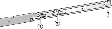
Figure 3-1 shows the rails and release levers that you need to install the CSACS 1120 Series appliance in a 4-post rack.
Figure 3-1 Release Levers on the Slide Rail Hardware
The following table describes the callouts in Figure 3-1.
Table 3-1 lists the contents of the rack-mount hardware kit (Cisco part number CSACS-1U-RAILS).
Table 3-1 Rack-Mount Hardware Kit
Slide rails
2
Multi-pin adapters
4
Fastener screws
4
Depending on the type of holes that your rack has, you will use different hardware to attach the appliance to the rack:
•
•
Note
Proceed to the next section, Installing the Slide Rails into a Rack with Square Holes, to continue the installation process.
Installing the Slide Rails into a Rack with Square Holes
This section contains:
•
•
Setting the Multi-Pin Adapters for the Rack Type
The multi-pin adapters allow the slide rails to be used in racks that have square mounting holes or round mounting holes.
To set the adapters for the rack type:
Step 1
Step 2
Step 3
Step 4
a.
Note
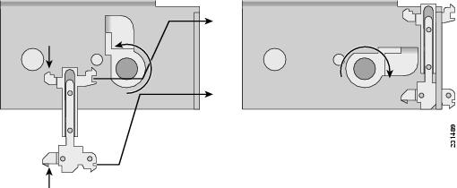
Figure 3-2 Locking the Adapter into Place
b.
If the adapter is seated properly, you should be able to easily rotate the swivel lock to the fully locked (closed) position.
Proceed to the next section, Installing and Securing the Slide Rails in a Rack, to continue the installation.
Installing and Securing the Slide Rails in a Rack
Caution
To install the slide rails into the rack:
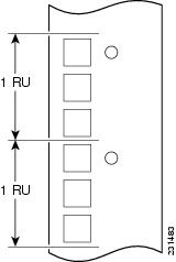
Step 1
Figure 3-3 Mounting Position Marks on a Rack
Step 2
Step 3
Figure 3-4 Inserting the Adapter Pins into the Mounting Holes
The following table describes the callouts in Figure 3-4.
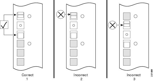
Figure 3-5 Correct and Incorrect Adapter Pin Insertion
The following table describes some of the correct and incorrect ways to insert the adapter pins into the rack as shown in Figure 3-5.
Step 4
Step 5
Step 6
Proceed to Installing the Slide Rails into a Rack with Round Holes to continue the installation process.
Installing the Slide Rails into a Rack with Round Holes
Installing the slide rails into a rack with round holes requires rack screws (not included in the rack-mount installation kit). Before you begin the installation, obtain the appropriate rack screws.
Caution
Note
Installing the slide rails on a round-hole rack does not require the multi-pin adapters. If the multi-pin adapters are already installed in the slide rails, remove them by rotating the swivel lock upward, pressing the mounting pins together, and then pulling the adapter from the multi-pin bracket, as shown in Figure 3-2.
To install the slide rails into the rack:
Step 1
Step 2
Step 3
Step 4
Step 5
Step 6
Proceed to the next section, Installing the Appliance into the Slide Rails, to continue the installation.
Installing the Appliance into the Slide Rails
To install the CSACS 1120 Series appliance into the slide rails:
Step 1
Step 2
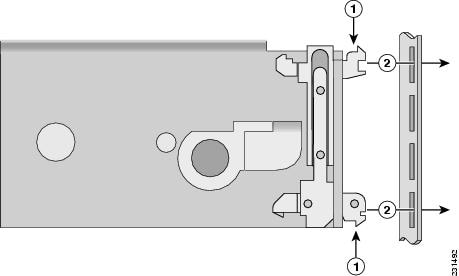
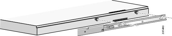
Figure 3-6 Aligning the Slide Rail with the Mounting Studs
Step 3
The component release levers (one on each slide rail) pivot to lock when the studs are fully engaged in the mounting channels, and then to release the studs when you press the release. Ensure that the component release levers are in the locked position.
Step 4
Connecting Cables
This section describes how to connect your CSACS 1120 Series appliance to the network and the appliance console. This section includes:
•
•
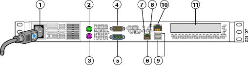
Figure 3-7 CSACS 1120 Series Appliance Rear View
The following table describes the callouts in Figure 3-7.
.
Note
Connecting to the AC Power Source
Warning
Connect the AC power receptacle to the AC power source with the provided power cable.
Connecting the Network Interface
Warning
This section describes how to connect the CSACS 1120 Series appliance NIC port.
The RJ-45 port supports standard straight-through and crossover Category 5 unshielded twisted-pair (UTP) cables. Cisco does not supply Category 5 UTP cables; these cables are available commercially.
To connect the cable to the appliance NIC port:
Step 1
Step 2
Note
Step 3
Connecting the Console
Warning
Your CSACS 1120 Series appliance has a DCE-mode console port for connecting a console terminal to your appliance. The appliance uses a DB-9 serial connector for the console port. For more information, see Serial (Console) Port, page 1-8.
To connect a terminal or a PC running terminal-emulation software to the console port on the CSACS 1120 Series appliance:
Step 1
Step 2
Connecting the Keyboard and Video Monitor
Warning
This section describes how to connect a keyboard and video monitor to the CSACS 1120 Series appliance.
The CSACS 1120 supports two PS/2 connector ports which can be used to connect a keyboard and video monitor directly to the appliance.
To connect a keyboard and video monitor to the appliance:
Step 1
Step 2
Step 3
Step 4
Cable Management
Cable management is the most visual aspect of your appliance setup. However, cable management is often overlooked because it can be time consuming.
Equipment racks and enclosures house more equipment today than ever before. This growth has increased the need for organized cable management both inside and outside the rack. Poor cable management not only leads to damaged cables or increased time for adding or changing cables, but also blocks critical airflow or access. These problems can lead to inefficiencies in the performance of your equipment or even downtime.
There are many solutions to address cable management. They can range from simple cable management rings, to vertical or horizontal organizers, to troughs and ladders.
All CSACS 1120 Series appliance cables should be properly dressed so as not to interfere with each other or other pieces of equipment. Use local practices to ensure that the cables attached to your appliance are properly dressed.
Proceed to the next section, Powering Up the CSACS 1120 Series Appliance, to continue the installation process.
Powering Up the CSACS 1120 Series Appliance
Warning
Warning
This section contains:
Checklist for Power Up
You are ready to power up the CSACS 1120 Series appliance if:
•
•
Power-Up Procedure
To power up the CSACS 1120 Series appliance and verify its initialization and self-test, follow this procedure. When the procedure is completed, the appliance is ready to be configured.
Step 1
Step 2
Step 3
Step 4
The appliance should begin booting. Once the operating system boots, you are ready to initialize the basic software configuration.
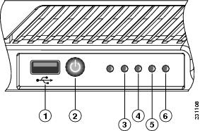
Figure 3-8 CSACS 1120 Series Appliance Front View
The following table describes the callouts in Figure 3-8.
USB port
Hard disk drive activity LED
Power button
NIC 1 LED
Appliance power LED
NIC 2 LED
Checking the LEDs
When the CSACS 1120 Series appliance is up and running, observe the front-panel LEDs. The following LEDs provide power, activity, and status information:
CSACS 1120 Appliance Front-Panel LEDs
•
–
–
•
–
–
•
–
–
For more detailed information about the LEDs, see Appendix D, "Troubleshooting."
Removing or Replacing the CSACS 1120 Series Appliance
Warning
Warning
This section contains:
•
•
Removing a CSACS 1120 Series Appliance
To remove a CSACS 1120 Series appliance from your network:
Step 1
Step 2
Step 3
The appliance is in constant communication on your network; thus, when the network notices that the appliance is no longer responding to it, the network stops sending requests to the appliance. This change is visible to users.
Note
Replacing a CSACS 1120 Series Appliance
To replace an appliance:
Step 1
Step 2
Configure the new appliance using the same configuration parameters that you used for the removed appliance.
Initial Configuration
The first three steps of the four steps that are required to configure the ACS, are documented in this manual:
•
•
•
Note
Establishing a Serial Console Connection
Before you can perform the initial configuration of ACS SE, you must establish a serial console connection to it. This procedure requires a PC, two DB-9 to RJ-45 adapters (provided), an RJ-45 cable (provided), and terminal emulation communication software (Hyper Terminal or equivalent).
To establish a serial console connection:
If you performed the procedure in Connecting Cables, you can skip to Step 2.
Step 1
a.
b.
c.
Tip
Step 2
Tip
Step 3
Note
•
•
•
•
•
Result: The
login: prompt appears.
Configuring CSACS 1120
You must configure the CSACS 1120 when you boot the system for the first time and whenever you re-image the system. For more information on re-imaging the system, see Upgrade Scenarios.
Table 3-2 lists the essential configuration tasks that are unique to SE.
Table 3-2 SE Configuration Tasks
Remote Agent configuration
On Cisco.com:
System Configuration
On Cisco.com:
ACS Back up
On Cisco.com:
ACS Restore
On Cisco.com:
Certificate setup
On Cisco.com:
EAP-FAST PAC files configuration
On Cisco.com:
Date/Time configuration
On Cisco.com:
SNMP setup
On Cisco.com:
Before you begin to configure the CSACS 1120, you should have the following information:
•
•
•
•
•
•
•
•
To configure CSACS 1120:
Step 1
Note
Step 2
loginprompt:Cisco Secure ACS: [version number]Appliance Management Software: [version number]Appliance Base Image: [version number]CSA build [version number]: (Patch: [version number])Status: Appliance is functioning properlyThe ACS Appliance has not been configured. Logon as "Administrator" with password "setup" to configure appliance.
Note
Cisco Secure ACS: [version number]prompt appears, you must reboot the appliance and then log in.Step 3
Appliance Management Software: [version number]prompt, enter Administrator, and press Enter.
Note
Step 4
Note
Result: The console displays:
Initialize Appliance.Machine will be rebooted after initialization.Entering Ctrl-C before setting appliance name will shutdown the applianceStep 5
Tip
Result: The console displays:
ACS Appliance name is set toxxx.Step 6
Appliance Base Image: [version number]DNS domain [ ]: prompt, enter the domain name, and press Enter.Result: The console displays:
DNS name is set toxxx.com.You need to set the administrator account name and password.Step 7
Tip
Step 8
Note
Step 9
Result: The console displays:
Password is set successfully.Administrator name is set toxxx.Step 10
Please enter the Encryption Password for the Configuration Store.Please note this is different from the administrator account,it is used to encrypt the Database.
Note
Step 11
Step 12
Result: The console displays:
Password is set successfully.Step 13
Note
Step 14
a.
CSA build [version number]: (Patch: [version number])enter the new GUI administrator name.The following prompt appears:
Enter new password:b.
Note
The following prompt appears:
Enter new password again:c.
Result: The console displays:
GUI Administrator added successfully.For more information on adding a GUI administrator account, see Setting Up a GUI Administrator Account.
Step 15
Status: Appliance is functioning properlyprompt, enter Y for yes or N for no, and press Enter.
Note
Note
Step 16
No change to the configuration.Accept network setting [Yes]a.
The ACS Appliance has not been configured. Logon as "Administrator" with password "setup" to configure appliance.prompt, enter the IP address, and press Enter.b.
loginprompt, enter the subnet mask value, and press Enter.c.
login:prompt, enter the default gateway value, and press Enter.d.
Initialize Applianceprompt, enter the address of any DNS server that you intend to use (separate each by a single space), and press Enter.
Note
Machine will be rebooted after initialization[xx.xx.xx.xx] prompt. If you do not configure the CSACS 1120 to use a DNS server, you must respond to all prompts for hostname or IP address only with an IP address.Result: The console displays:
IP Address is reconfigured.e.
Entering Ctrl-C before setting appliance name will shutdown the applianceprompt, enter Y, and press Enter.Result: The console displays:
New ip address is set.Default gateway is set toxx.xx.xx.xxDNS servers are set to:xx.xx.xx.xx xx.xx.xx.xx.f.
ACS Appliance name is set toprompt, enter Y, and press Enter.Result: The IP address for the appliance will be set.
g.
prompt, enter Y, and press Enter.
Tip
h.
DNS name is set toprompt, enter the IP address or hostname of a device connected to the , and press Enter.Result: If successful, the system displays the ping statistics and displays the Test network connectivity prompt.
i.
You need to set the administrator account name and password.prompt, enter N, and press Enter.
Tip
Step 17
Password is set successfully.prompt, enter Y, and press Enter.Result: The console displays:
Current Date Time Setting:Time Zone: (GMT -xx:xx) XXX TimeDate and Time: mm/dd/yyyyNTP Server(s): NTP Synchronization Disabled.Step 18
Administrator name is set toprompt, enter Y, and press Enter.Result: The console displays a numbered list of time zones.
Step 19
Please enter the Encryption Password for the Configuration Store.prompt, enter the index number of the appropriate time zone for your geography and, press Enter.Result: The console displays the new time zone.
Step 20
Please note this is different from the administrator account,prompt, do one of the following:•
•
Tip
Result: The console displays a confirmation message reflecting your choice.
Step 21
it is used to encrypt the Database.prompt, enter the date in the given format, and press Enter.Step 22
Password is set successfully.prompt, enter the current time in the given format, and press Enter.Result: The console displays:
Initial configuration is successful. Appliance will now reboot.The system reboots.
Verifying the Initial Configuration
To verify that you have correctly completed the CSACS 1120 initial configuration:
Before You Begin
Establish a serial console connection to the CSACS 1120. For details, see Configuring CSACS 1120.
Step 1
Result: When the system boots, a
Enter new GUI administrator name: prompt appears,prompt appears on the console.Step 2
Enter new password:prompt, enter the new administrator name, and press Enter.Step 3
Enter new password again:prompt, enter the password you created during initial configuration, and press Enter.Step 4
GUI Administrator added successfully.prompt, enter show and press Enter.Result: The console displays the status information.
Step 5
Setting Up a GUI Administrator Account
After initial installation or re-imaging, unless you specified a GUI administrator account during the initial configuration using the setup script, only one administrator account exists: the CLI administrator account. This account allows access only through a serial console log in and CLI commands.
If you specified a GUI administrator account when prompted for one by the setup script, a GUI administrator account exists. However, before the designated GUI administrator user can use this account, you must unlock it by entering the unlock guiadmin command.
You can also set up an additional GUI administrator account that can access the CSACS 1120.
To set up an initial web GUI account:
Step 1
Step 2
unlock guiadmin <Admin> <Password>where Admin is the name of the GUI administrator account and Password is the password for the account.
Step 3
add guiadmin
Result: The console displays:
Adding new GUI AdministratorNote! All ACS services will be restarted.GUI Administrator password policy is:Password must be at least 4 character(s) long.Step 4
Use Static IP Address [Yes]:prompt, enter the new GUI administrator name, and press Enter.Step 5
No change to the configuration.prompt, enter the new password, and press Enter.
Note
Step 6
Result: The console displays:
GUI Administrator added successfully.The new GUI administrator account is not usable until
you unlock it by entering the unlock guiadmin command.
Now, you can now use the GUI administrator account to remotely access the ACS GUI running on the CSACS 1120.
Next Steps
After you have successfully performed the procedures in this guide, CSACS 1120 is installed and initially configured. The next step is to log in using the GUI administrator account and use a browser and the web interface to fully configure the CSACS 1120 to provide the AAA services that you want from this installation. The HTML address is in the following format: http://<ip address>:2002, where ip address is the address that you assign during configuration.
For information on setting up user, group, network, and other parameters, see the User Guide for Cisco Secure ACS 4.2.
Note