- Assigning an ID Number to a VPN
- Configuring MPLS Layer 3 VPNs
- Configuring Route Maps to Control the Distribution of MPLS Labels Between Routers in an MPLS VPN
- Configuring Scalable Hub-and-Spoke MPLS VPNs
- Dialing to Destinations with the Same IP Address for MPLS VPNs
- Directing MPLS VPN Traffic Using Policy-Based Routing
- Directing MPLS VPN Traffic Using a Source IP Address
- Ensuring That MPLS VPN Clients Using OSPF Communicate over the MPLS VPN Backbone Instead of Through Backdoor Links
- Multi-VRF Selection Using Policy Based Routing (PBR)
- MPLS Multi-VRF (VRF Lite) Support
- MPLS VPN Half-Duplex VRF
- MPLS VPN�VRF CLI for IPv4 and IPv6 VPNs
- MPLS VPN�Show Running VRF
- MPLS VPN�Route Target Rewrite
- MPLS VPN: VRF Selection Based on Source IP Address
- MPLS VPN: VRF Selection Using Policy Based Routing
- MPLS VPN--BGP Local Convergence
MPLS: Layer 3 VPNs Configuration Guide, Cisco IOS Release x.x
Bias-Free Language
The documentation set for this product strives to use bias-free language. For the purposes of this documentation set, bias-free is defined as language that does not imply discrimination based on age, disability, gender, racial identity, ethnic identity, sexual orientation, socioeconomic status, and intersectionality. Exceptions may be present in the documentation due to language that is hardcoded in the user interfaces of the product software, language used based on RFP documentation, or language that is used by a referenced third-party product. Learn more about how Cisco is using Inclusive Language.
- Updated:
- February 12, 2008
Chapter: Configuring Scalable Hub-and-Spoke MPLS VPNs
- Contents
- Prerequisites for Configuring Scalable Hub-and-Spoke MPLS VPNs
- Restrictions for Configuring Scalable Hub-and-Spoke MPLS VPNs
- Information about Configuring Scalable Hub-and-Spoke MPLS VPNs
- How to Ensure that MPLS VPN Clients Use the Hub PE Router
- Configuration Examples for Configuring Scalable Hub-and-Spoke MPLS VPNs
- Additional References
- Feature Information for Configuring Scalable Hub-and-Spoke MPLS VPNs
Configuring Scalable Hub-and-Spoke MPLS VPNs
This module explains how to ensure that virtual private network (VPN) clients that connect to the same provider edge (PE) router at the edge of the Mutliprotocol (MPLS) Virtual Private Network (VPN) use the hub site. This feature prevents the VPN clients from communicating directly with each other, bypassing the hub site. This feature also provides scalable hub-and-spoke connectivity for subscribers of an MPLS VPN service by removing the requirement of one VRF per spoke.
Module History
This module was first published on May 2, 2005, and last updated on May 2, 2005.
Finding Feature Information in This Module
Your Cisco IOS software release may not support all features. To find information about feature support and configuration, use the "Feature Information for Configuring Scalable Hub-and-Spoke MPLS VPNs" section.
Contents
•![]() Prerequisites for Configuring Scalable Hub-and-Spoke MPLS VPNs
Prerequisites for Configuring Scalable Hub-and-Spoke MPLS VPNs
•![]() Restrictions for Configuring Scalable Hub-and-Spoke MPLS VPNs
Restrictions for Configuring Scalable Hub-and-Spoke MPLS VPNs
•![]() Information about Configuring Scalable Hub-and-Spoke MPLS VPNs
Information about Configuring Scalable Hub-and-Spoke MPLS VPNs
•![]() How to Ensure that MPLS VPN Clients Use the Hub PE Router
How to Ensure that MPLS VPN Clients Use the Hub PE Router
•![]() Configuration Examples for Configuring Scalable Hub-and-Spoke MPLS VPNs
Configuration Examples for Configuring Scalable Hub-and-Spoke MPLS VPNs
•![]() Feature Information for Configuring Scalable Hub-and-Spoke MPLS VPNs
Feature Information for Configuring Scalable Hub-and-Spoke MPLS VPNs
Prerequisites for Configuring Scalable Hub-and-Spoke MPLS VPNs
You must have a working MPLS core network.
Restrictions for Configuring Scalable Hub-and-Spoke MPLS VPNs
•![]() In both the upstream and downstream VRFs, routing protocols are not supported on interfaces configured with this feature. Interfaces that are not configured with this feature, however, do not have this restriction for the upstream or downstream VRFs.
In both the upstream and downstream VRFs, routing protocols are not supported on interfaces configured with this feature. Interfaces that are not configured with this feature, however, do not have this restriction for the upstream or downstream VRFs.
•![]() You can configure this feature only on virtual access interfaces (VAIs) and virtual template interfaces (VTIs).
You can configure this feature only on virtual access interfaces (VAIs) and virtual template interfaces (VTIs).
•![]() Only unnumbered interfaces are supported.
Only unnumbered interfaces are supported.
•![]() Multicast is not supported on interfaces configured for hub-and-spoke MPLS VPNs.
Multicast is not supported on interfaces configured for hub-and-spoke MPLS VPNs.
Information about Configuring Scalable Hub-and-Spoke MPLS VPNs
To configure this feature, you need to understand the following concepts:
•![]() Reverse Path Forwarding Check
Reverse Path Forwarding Check
Overview
This feature prevents local connectivity between subscribers at the spoke provider edge (PE) router and ensures that a hub site provides subscriber connectivity. Any sites that connect to the same PE router must forward intersite traffic using the hub site. This ensures that the routing done at the spoke site moves from the access-side interface to the network-side interface or from the network-side interface to the access-side interface, but never from the access-side interface to the access-side interface.
This feature prevents situations where the PE router locally switches the spokes without passing the traffic through the hub site. This prevents subscribers from directly connecting to each other.
This feature eases configuration by removing the requirement of one VRF per spoke. In prior releases, when spokes connected to the same PE router, each spoke was configured in a separate VRF to ensure that the traffic between the spokes traversed the central link between the wholesale service provider and the ISP. However, this solution was not scalable. When many spokes connected to the same PE router, configuration of VRFs for each spoke became quite complex and greatly increased memory usage. This was especially true in large-scale environments that supported high-density remote access to Layer 3 VPNs.
Figure 2 shows a sample hub-and-spoke topology.
Figure 2 Hub-and-Spoke Topology
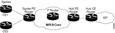
Upstream and Downstream VRFs
This feature uses two unidirectional VRFs to forward IP traffic between the spokes and the hub PE router:
•![]() The upstream VRF forwards the IP traffic from the spokes toward the hub PE router. This VRF typically contains only a default route but might also contain summary routes and multiple default routes. The default route points to the interface on the hub PE router that connects to the upstream ISP. The router dynamically learns about the default route from the routing updates that the hub PE router or home gateway sends. The upstream VRF also contains the VAIs that connect the spokes, but it contains no other local interfaces.
The upstream VRF forwards the IP traffic from the spokes toward the hub PE router. This VRF typically contains only a default route but might also contain summary routes and multiple default routes. The default route points to the interface on the hub PE router that connects to the upstream ISP. The router dynamically learns about the default route from the routing updates that the hub PE router or home gateway sends. The upstream VRF also contains the VAIs that connect the spokes, but it contains no other local interfaces.
•![]() The downstream VRF forwards traffic from the hub PE router back to the spokes. This VRF contains Point-to-Point Protocol (PPP) peer routes for the spokes and per-user static routes received from the Authentication, Authorization, and Accounting (AAA) server. It also contains the routes imported from the hub PE router.
The downstream VRF forwards traffic from the hub PE router back to the spokes. This VRF contains Point-to-Point Protocol (PPP) peer routes for the spokes and per-user static routes received from the Authentication, Authorization, and Accounting (AAA) server. It also contains the routes imported from the hub PE router.
The router redistributes routes from the downstream VRF into Multiprotocol Border Gateway Protocol (MP-BGP). The spoke PE router typically advertises a summary route across the MPLS core for the connected spokes. The VRF configured on the hub PE router imports the advertised summary route.
Reverse Path Forwarding Check
The unicast Reverse Path Forwarding (RPF) check ensures that an IP packet that enters a router uses the correct inbound interface. This feature supports unicast RPF check on the spoke-side interfaces. Because different VRFs are used for downstream and upstream forwarding, the RPF mechanism ensures that source address checks occur in the downstream VRF.
How to Ensure that MPLS VPN Clients Use the Hub PE Router
This section contains the following procedures:
•![]() Configuring the Upstream and Downstream VRFs on the PE Router or the Spoke PE Router (required)
Configuring the Upstream and Downstream VRFs on the PE Router or the Spoke PE Router (required)
•![]() Associating VRFs (required)
Associating VRFs (required)
•![]() Configuring the Downstream VRF for an AAA Server (optional)
Configuring the Downstream VRF for an AAA Server (optional)
•![]() Verifying the Configuration (optional)
Verifying the Configuration (optional)
Configuring the Upstream and Downstream VRFs on the PE Router or the Spoke PE Router
To configure the upstream and downstream VRFs on the PE router or on the spoke PE router, use the following procedure.
SUMMARY STEPS
1. ![]() enable
enable
2. ![]() configure terminal
configure terminal
3. ![]() ip vrf vrf-name
ip vrf vrf-name
4. ![]() rd route-distinguisher
rd route-distinguisher
5. ![]() route-target {import | export | both} route-target-ext-community
route-target {import | export | both} route-target-ext-community
6. ![]() exit
exit
DETAILED STEPS
Associating VRFs
The virtual template interface is used to create and configure a virtual access interface (VAI). After you define and configure the VRFs on the PE routers, associate each VRF with the following:
•![]() Interface or subinterface
Interface or subinterface
•![]() Virtual template interface
Virtual template interface
To associate a VRF, enter the following commands on the PE router.
SUMMARY STEPS
1. ![]() enable
enable
2. ![]() configure terminal
configure terminal
3. ![]() interface virtual-template number
interface virtual-template number
4. ![]() ip vrf forwarding vrf-name1 [downstream vrf-name2]
ip vrf forwarding vrf-name1 [downstream vrf-name2]
5. ![]() ip unnumbered type number
ip unnumbered type number
6. ![]() exit
exit
DETAILED STEPS
Configuring the Downstream VRF for an AAA Server
To configure the downstream VRF for an AAA server, enter the following Cisco attribute value:
lcp:interface-config=ip vrf forwarding U downstream D
For more information about configuring a RADIUS server, see Configuring Virtual Template Interfaces.
Verifying the Configuration
To verify the configuration, perform the following steps.
SUMMARY STEPS
1. ![]() show ip vrf [brief | detail | interfaces | id] [vrf-name] [output-modifiers]
show ip vrf [brief | detail | interfaces | id] [vrf-name] [output-modifiers]
2. ![]() show ip route vrf vrf-name
show ip route vrf vrf-name
3. ![]() show running-config [interface type number]
show running-config [interface type number]
DETAILED STEPS
Step 1 ![]() show ip vrf [brief | detail | interfaces | id] [vrf-name] [output-modifiers]
show ip vrf [brief | detail | interfaces | id] [vrf-name] [output-modifiers]
Use this command to display information about all of the VRFs configured on the router, including the downstream VRF for each associated VAI.
Router# show ip vrf
Name Default RD Interface
D 2:0 Loopback2
Virtual-Access3 [D]
Virtual-Access4 [D]
U 2:1 Virtual-Access3
Virtual-Access4
show ip vrf detail vrf-name
Use this command to display detailed information about the VRF you specify, including all of the VAIs associated with the VRF.
If you do not specify a value for vrf-name, detailed information about all of the VRFs configured on the router appears, including all of the VAIs associated with each VRF.
The following example shows how to display detailed information for the VRF called vrf1.
Router# show ip vrf detail vrf1
VRF D; default RD 2:0; default VPNID <not set>
Interfaces:
Loopback2 Virtual-Access3 [D] Virtual-Access4 [D]
Connected addresses are not in global routing table
Export VPN route-target communities
RT:2:0
Import VPN route-target communities
RT:2:1
No import route-map
No export route-map
VRF U; default RD 2:1; default VPNID <not set>
Interfaces:
Virtual-Access3 Virtual-Access4
Connected addresses are not in global routing table
No Export VPN route-target communities
Import VPN route-target communities
RT:2:1
No import route-map
No export route-map
Step 2 ![]() show ip route vrf vrf-name
show ip route vrf vrf-name
Use this command to display the IP routing table for the VRF you specify, and information about the per-user static routes installed in the downstream VRF.
The following example shows how to display the routing table for the downstream VRF named D.
Router# show ip route vrf D
Routing Table: D
Codes: C - connected, S - static, R - RIP, M - mobile, B - BGP
D - EIGRP, EX - EIGRP external, O - OSPF, IA - OSPF inter area
N1 - OSPF NSSA external type 1, N2 - OSPF NSSA external type 2
E1 - OSPF external type 1, E2 - OSPF external type 2
i - IS-IS, L1 - IS-IS level-1, L2 - IS-IS level-2, ia - IS-IS inter
area
* - candidate default, U - per-user static route, o - ODR
P - periodic downloaded static route
Gateway of last resort is not set
2.0.0.0/8 is variably subnetted, 5 subnets, 2 masks
U 2.0.0.2/32 [1/0] via 2.8.1.1
S 2.0.0.0/8 is directly connected, Null0
U 2.0.0.5/32 [1/0] via 2.8.1.2
C 2.8.1.2/32 is directly connected, Virtual-Access4
C 2.8.1.1/32 is directly connected, Virtual-Access3
The following example shows how to display the routing table for the upstream VRF named U.
Router# show ip route vrf U
Routing Table: U
Codes: C - connected, S - static, R - RIP, M - mobile, B - BGP
D - EIGRP, EX - EIGRP external, O - OSPF, IA - OSPF inter area
N1 - OSPF NSSA external type 1, N2 - OSPF NSSA external type 2
E1 - OSPF external type 1, E2 - OSPF external type 2
i - IS-IS, L1 - IS-IS level-1, L2 - IS-IS level-2, ia - IS-IS interarea
* - candidate default, U - per-user static route, o - ODR
P - periodic downloaded static route
Gateway of last resort is 100.0.0.20 to network 0.0.0.0
2.0.0.0/32 is subnetted, 1 subnets
C 2.0.0.8 is directly connected, Loopback2
B* 0.0.0.0/0 [200/0] via 100.0.0.20, 1w5d
Step 3 ![]() show running-config [interface type number]
show running-config [interface type number]
Use this command to display information about the virtual access interface you specify, including information about the upstream and downstream VRFs.
The following example shows how to display information about the interface named virtual-access 3.
Router# show running-config interface virtual-access 3
Building configuration...
Current configuration : 92 bytes
!
interface Virtual-Access3
ip vrf forwarding U downstream D
ip unnumbered Loopback2
end
The following example shows how to display information about the interface named virtual-access 4.
Router# show running-config interface virtual-access 4
Building configuration...
Current configuration : 92 bytes
!
interface Virtual-Access4
ip vrf forwarding U downstream D
ip unnumbered Loopback2
end
Configuration Examples for Configuring Scalable Hub-and-Spoke MPLS VPNs
This section provides the following configuration examples:
•![]() Configuring the Upstream and Downstream VRFs on the PE Router and the Spoke PE Router: Example
Configuring the Upstream and Downstream VRFs on the PE Router and the Spoke PE Router: Example
•![]() Configuring Scalable Hub-and-Spoke MPLS VPNs—Basic Configuration: Example
Configuring Scalable Hub-and-Spoke MPLS VPNs—Basic Configuration: Example
•![]() Configuring Scalable Hub-and-Spoke MPLS VPNs: Example
Configuring Scalable Hub-and-Spoke MPLS VPNs: Example
Configuring the Upstream and Downstream VRFs on the PE Router and the Spoke PE Router: Example
The following example configures an upstream VRF named U:
Router> enable
Router# configure terminal
Router(config)# ip vrf U
Router(config-vrf)# rd 1:0
Router(config-vrf)# route-target import 1:0
The following example configures a downstream VRF named D:
Router> enable
Router# configure terminal
Router(config)# ip vrf D
Router(config-vrf)# rd 1:8
Router(config-vrf)# route-target export 1:100
Associating VRFs: Example
The following example associates the VRF named U with the virtual-template 1 interface and specifies the downstream VRF named D:
Router> enable
Router# configure terminal
Router(config)# interface virtual-template 1
Router(config-if)# ip vrf forwarding U downstream D
Router(config-if)# ip unnumbered Loopback1
Configuring Scalable Hub-and-Spoke MPLS VPNs—Basic Configuration: Example
In this example, local authentication is used; that is, the RADIUS server is not used.
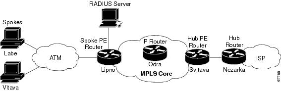
This example uses the hub-and-spoke topology shown in Figure 3.
Figure 3 Sample Topology
ip vrf D
rd 1:8
route-target export 1:100
!
ip vrf U
rd 1:0
route-target import 1:0
!
ip cef
vpdn enable
!
vpdn-group U
accept-dialin
protocol pppoe
virtual-template 1
!
interface Loopback2
ip vrf forwarding U
ip address 2.0.0.8 255.255.255.255
!
interface ATM2/0
description Mze ATM3/1/2
no ip address
no atm ilmi-keepalive
pvc 0/16 ilmi
!
pvc 3/100
protocol pppoe
!
pvc 3/101
protocol pppoe
!
interface Virtual-Template1
ip vrf forwarding U downstream D
ip unnumbered Loopback2
peer default ip address pool U-pool
ppp authentication chap
Configuring Scalable Hub-and-Spoke MPLS VPNs: Example
The following example shows how to connect two Point-to-Point Protocol over Ethernet (PPPoE) clients to a single VRF pair on the spoke PE router named Lipno. Although both PPPoE clients are configured in the same VRF, all communication occurs using the hub PE router. Half-duplex VRFs are configured on the spoke PE. The client configuration is downloaded to the spoke PE from the RADIUS server.
This example uses the hub-and-spoke topology shown in Figure 3.

Note ![]() The wholesale provider can forward the user authentication request to the corresponding ISP. If the ISP authenticates the user, the wholesale provider appends the VRF information to the request that goes back to the PE router.
The wholesale provider can forward the user authentication request to the corresponding ISP. If the ISP authenticates the user, the wholesale provider appends the VRF information to the request that goes back to the PE router.
aaa new-model
!
aaa group server radius R
server 22.0.20.26 auth-port 1812 acct-port 1813
!
aaa authentication ppp default group radius
aaa authorization network default group radius
!
ip vrf D
description Downstream VRF - to spokes
rd 1:8
route-target export 1:100
!
ip vrf U
description Upstream VRF - to hub
rd 1:0
route-target import 1:0
!
ip cef
vpdn enable
!
vpdn-group U
accept-dialin
protocol pppoe
virtual-template 1
!
interface Loopback2
ip vrf forwarding U
ip address 2.0.0.8 255.255.255.255
!
interface ATM2/0
pvc 3/100
protocol pppoe
!
pvc 3/101
protocol pppoe
!
interface virtual-template 1
no ip address
ppp authentication chap
!
router bgp 1
no synchronization
neighbor 100.0.0.34 remote-as 1
neighbor 100.0.0.34 update-source Loopback0
no auto-summary
!
address-family vpnv4
neighbor 100.0.0.34 activate
neighbor 100.0.0.34 send-community extended
auto-summary
exit-address-family
!
address-family ipv4 vrf U
no auto-summary
no synchronization
exit-address-family
!
address-family ipv4 vrf D
redistribute static
no auto-summary
no synchronization
exit-address-family
!
ip local pool U-pool 2.8.1.1 2.8.1.100
ip route vrf D 2.0.0.0 255.0.0.0 Null0
!
radius-server host 22.0.20.26 auth-port 1812 acct-port 1813
radius-server key cisco
Additional References
The following sections provide references related to MPLS VPNs.
Related Documents
|
|
|
|---|---|
Basic MPLS VPNs |
|
MPLS VPN Carrier Supporting Carrier |
• |
MPLS VPN InterAutonomous Systems |
• |
Standards
|
|
|
|---|---|
No new or modified standards are supported by this feature, and support for existing standards has not been modified by this feature. |
— |
MIBs
RFCs
|
|
|
|---|---|
RFC 2547 |
BGP/MPLS VPNs |
Technical Assistance
Feature Information for Configuring Scalable Hub-and-Spoke MPLS VPNs
Table 1 lists the features in this module and provides links to specific configuration information.
Not all commands may be available in your Cisco IOS software release. For details on when support for specific commands was introduced, see the command reference documents.
Cisco IOS software images are specific to a Cisco IOS software release, a feature set, and a platform. Use Cisco Feature Navigator to find information about platform support and Cisco IOS software image support. Access Cisco Feature Navigator at http://www.cisco.com/go/fn. You must have an account on Cisco.com. If you do not have an account or have forgotten your username or password, click Cancel at the login dialog box and follow the instructions that appear.
Note ![]() Table 1 lists only the Cisco IOS software release that introduced support for a given feature in a given Cisco IOS software release train. Unless noted otherwise, subsequent releases of that Cisco IOS software release train also support that feature.
Table 1 lists only the Cisco IOS software release that introduced support for a given feature in a given Cisco IOS software release train. Unless noted otherwise, subsequent releases of that Cisco IOS software release train also support that feature.
|
|
|
|
|---|---|---|
MPLS VPN: Half Duplex VRF Support |
12.3(6) 12.3(11)T |
This feature ensures that VPN clients that connect to the same PE router at the edge of the MPLS VPN use the hub site to communicate. The following sections provide information about this feature: • |

 Feedback