- Assigning an ID Number to a VPN
- Configuring MPLS Layer 3 VPNs
- Configuring Route Maps to Control the Distribution of MPLS Labels Between Routers in an MPLS VPN
- Configuring Scalable Hub-and-Spoke MPLS VPNs
- Dialing to Destinations with the Same IP Address for MPLS VPNs
- Directing MPLS VPN Traffic Using Policy-Based Routing
- Directing MPLS VPN Traffic Using a Source IP Address
- Ensuring That MPLS VPN Clients Using OSPF Communicate over the MPLS VPN Backbone Instead of Through Backdoor Links
- Multi-VRF Selection Using Policy Based Routing (PBR)
- MPLS Multi-VRF (VRF Lite) Support
- MPLS VPN Half-Duplex VRF
- MPLS VPN�VRF CLI for IPv4 and IPv6 VPNs
- MPLS VPN�Show Running VRF
- MPLS VPN�Route Target Rewrite
- MPLS VPN: VRF Selection Based on Source IP Address
- MPLS VPN: VRF Selection Using Policy Based Routing
- MPLS VPN--BGP Local Convergence
MPLS: Layer 3 VPNs Configuration Guide, Cisco IOS Release x.x
Bias-Free Language
The documentation set for this product strives to use bias-free language. For the purposes of this documentation set, bias-free is defined as language that does not imply discrimination based on age, disability, gender, racial identity, ethnic identity, sexual orientation, socioeconomic status, and intersectionality. Exceptions may be present in the documentation due to language that is hardcoded in the user interfaces of the product software, language used based on RFP documentation, or language that is used by a referenced third-party product. Learn more about how Cisco is using Inclusive Language.
- Updated:
- February 12, 2008
Chapter: Dialing to Destinations with the Same IP Address for MPLS VPNs
- Contents
- Prerequisites for Dialing to Destinations with the Same IP Address
- Restrictions for Dialing to Destinations with the Same IP Address
- Information About Dialing to Destinations with the Same IP Address
- How to Enable Dialing to Destinations with the Same IP Address
Dialing to Destinations with the Same IP Address for MPLS VPNs
The dialer software in Cisco IOS prior to Release 12.2(8)T had no way to dial two different destinations with the same IP address. More specifically, in networks where a network access server (NAS) supports dialing clients with overlapping addresses, dial-out attempts fail. This module explains how to dial to more than one destination with the same IP address.
Module History
This module was first published on May 2, 2005, and last updated on May 2, 2005.
Finding Feature Information in This Module
Your Cisco IOS software release may not support all features. To find information about feature support and configuration, use the "Feature Information for Dialing to Destinations with the Same IP Address" section.
Contents
•![]() Prerequisites for Dialing to Destinations with the Same IP Address
Prerequisites for Dialing to Destinations with the Same IP Address
•![]() Restrictions for Dialing to Destinations with the Same IP Address
Restrictions for Dialing to Destinations with the Same IP Address
•![]() Information About Dialing to Destinations with the Same IP Address
Information About Dialing to Destinations with the Same IP Address
•![]() How to Enable Dialing to Destinations with the Same IP Address
How to Enable Dialing to Destinations with the Same IP Address
•![]() Configuration Examples for Dialing to Destinations with the Same IP Address
Configuration Examples for Dialing to Destinations with the Same IP Address
•![]() Feature Information for Dialing to Destinations with the Same IP Address
Feature Information for Dialing to Destinations with the Same IP Address
Prerequisites for Dialing to Destinations with the Same IP Address
Before configuring this feature, you should understand how to configure the following network features:
•![]() Virtual profiles with two-way AAA authentication
Virtual profiles with two-way AAA authentication
•![]() MPLS VPNs
MPLS VPNs
Refer to the documents listed in the "Additional References" section for information about configuring these features.
Restrictions for Dialing to Destinations with the Same IP Address
When configuring static routes in an MPLS or MPLS VPN environment, some variations of the ip route and ip route vrf commands are not supported. These variations of the commands are not supported in Cisco IOS releases that support the Tag Forwarding Information Base (TFIB), specifically Cisco IOS Releases 12.xT, 12.xM, and 12.0S. The TFIB cannot resolve prefixes when the recursive route over which the prefixes travel disappears and then reappears. However, the command variations are supported in Cisco IOS releases that support the MPLS Forwarding Infrastructure (MFI), specifically Cisco IOS Release 12.2(25)S and later. Use the following guidelines when configuring static routes.
Supported Static Routes in an MPLS Environment
The following ip route command is supported when you configure static routes in MPLS environment:
ip route destination-prefix mask interface next-hop-address
The following ip route commands are supported when you configure static routes in an MPLS environment and configure load sharing with static nonrecursive routes and a specific outbound interface:
ip route destination-prefix mask interface1 next-hop1
ip route destination-prefix mask interface2 next-hop2
Unsupported Static Routes in an MPLS Environment that Uses the TFIB
The following ip route command is not supported when you configure static routes in an MPLS environment:
ip route destination-prefix mask next-hop-address
The following ip route command is not supported when you configure static routes in an MPLS environment and enable load sharing where the next hop can be reached through two paths:
ip route destination-prefix mask next-hop-address
The following ip route command is not supported when you configure static routes in an MPLS environment and enable load sharing where the destination can be reached through two next hops:
ip route destination-prefix mask next-hop1
ip route destination-prefix mask next-hop2
Use the interface an next-hop arguments when specifying static routes.
Supported Static Routes in an MPLS VPN Environment
The following ip route vrf commands are supported when you configure static routes in a MPLS VPN environment, and the next hop and interface are in the same VRF:
–![]() ip route vrf vrf-name destination-prefix mask next-hop-address
ip route vrf vrf-name destination-prefix mask next-hop-address
–![]() ip route vrf vrf-name destination-prefix mask interface next-hop-address
ip route vrf vrf-name destination-prefix mask interface next-hop-address
–![]() ip route vrf vrf-name destination-prefix mask interface1 next-hop1
ip route vrf vrf-name destination-prefix mask interface1 next-hop1
ip route vrf vrf-name destination-prefix mask interface2 next-hop2
The following ip route vrf commands are supported when you configure static routes in a MPLS VPN environment, and the next hop is in the global table in the MPLS cloud in the global routing table. For example, these commands are supported when the next hop is pointing to the Internet Gateway.
–![]() ip route vrf vrf-name destination-prefix mask next-hop-address global
ip route vrf vrf-name destination-prefix mask next-hop-address global
–![]() ip route vrf vrf-name destination-prefix mask interface next-hop-address
ip route vrf vrf-name destination-prefix mask interface next-hop-address
(This command is supported when the next hop and interface are in the core.)
The following ip route commands are supported when you configure static routes in a MPLS VPN environment and enable load sharing with static nonrecursive routes and a specific outbound interfaces:
ip route destination-prefix mask interface1 next-hop1
ip route destination-prefix mask interface2 next-hop2
Unsupported Static Routes in an MPLS VPN Environment that Uses the TFIB
The following ip route command is not supported when you configure static routes in a MPLS VPN environment, the next hop is in the global table in the MPLS cloud within the core, and you enable load sharing where the next hop can be reached through two paths:
ip route vrf destination-prefix mask next-hop-address global
The following ip route commands are not supported when you configure static routes in a MPLS VPN environment, the next hop is in the global table in the MPLS cloud within the core, and you enable load sharing where the destination can be reached through two next hops:
ip route vrf destination-prefix mask next-hop1 global
ip route vrf destination-prefix mask next-hop2 global
The following ip route vrf commands are not supported when you configure static routes in an MPLS VPN environment, and the next hop and interface are in the same VRF:
ip route vrf vrf-name destination-prefix mask next-hop1
ip route vrf vrf-name destination-prefix mask next-hop2
Supported Static Routes in an MPLS VPN Environment Where the Next Hop Resides in the Global Table on the CE Router
The following ip route vrf command is supported when you configure static routes in a MPLS VPN environment, and the next hop is in the global table on the CE side. For example, the following command is supported when the destination-prefix is the CE router's loopback address, as in EBGP multihop cases.
ip route vrf vrf-name destination-prefix mask interface next-hop-address
The following ip route commands are supported when you configure static routes in a MPLS VPN environment, the next hop is in the global table on the CE side, and you enable load sharing with static non-recursive routes and a specific outbound interfaces:
ip route destination-prefix mask interface1 nexthop1
ip route destination-prefix mask interface2 nexthop2
Information About Dialing to Destinations with the Same IP Address
Before configuring this feature, you should understand the following concepts:
•![]() Introduction to Dialing to Destinations with the Same IP Address
Introduction to Dialing to Destinations with the Same IP Address
Introduction to Dialing to Destinations with the Same IP Address
The Cisco IOS dialer software can distinguish between two destinations with the same IP address using information stored in the VRF. This capability is provided to the dialer software by two existing Cisco IOS commands, dialer map and ip route, which have been enhanced to include VPN routing and forwarding (VRF) information.
In previous Cisco IOS releases, the dialer software obtained the telephone number for dial-out based on the destination IP address configured in the dialer map command. Now, the enhanced dialer map command supplies the name of the VRF so that the telephone number to be dialed is based on the VRF name and the destination IP address. The VRF is identified based on the incoming interface of the packet, and is used with the destination IP address defined in the dialer map command to determine the telephone number to be dialed.
The ip route configuration command also includes the VRF information. When a packet arrives in an incoming interface that belongs to a particular VRF, only those ip route commands that correspond to that particular VRF are used to determine the destination interface.
Benefits of this Feature
This feature allows the dialer software to dial out in an MPLS-based VPN. The MPLS VPN model simplifies network routing. For example, rather than needing to manage routing over a complex virtual network backbone composed of many virtual circuits, an MPLS VPN user can employ the backbone of the service provider as the default route in communicating with all other VPN sites.
This default route capability allows several sites to transparently interconnect through the service provider network. One service provider network can support several different IP VPNs, each of which appears to its users as a separate, private network. Within a VPN, each site can send IP packets to any other site in the same VPN, because each VPN is associated with one or more VRFs. The VRF is a key element in the VPN technology, because it maintains the routing information that defines a customer VPN site.
How to Enable Dialing to Destinations with the Same IP Address
This section includes the following procedures:
•![]() Mapping the VRF and Next-Hop Address to a Dial String (required)
Mapping the VRF and Next-Hop Address to a Dial String (required)
•![]() Verifying the Configuration (optional)
Verifying the Configuration (optional)
Mapping the VRF and Next-Hop Address to a Dial String
Use the following procedure to map a VRF and next-hop address combination to a dial string and thereby allow the dialer software to be VRF-aware for an MPLS VPN.
Prerequisites
These commands are only part of the required configuration and show how to map a VRF and next-hop address combination to a dial string. Refer to the documents listed in the "Additional References" section and the example in the "Configuration Examples for Dialing to Destinations with the Same IP Address" section for details on where to include these commands in the network configuration.
SUMMARY STEPS
1. ![]() enable
enable
2. ![]() configure terminal
configure terminal
3. ![]() interface dialer number
interface dialer number
4. ![]() dialer map ip protocol-next-hop-address vrf vrf-name name host-name dial-string
dialer map ip protocol-next-hop-address vrf vrf-name name host-name dial-string
5. ![]() end
end
6. ![]() ip route vrf vrf-name ip-address mask interface-type interface-number
ip route vrf vrf-name ip-address mask interface-type interface-number
DETAILED STEPS
Verifying the Configuration
To verify the configuration, use the following procedure.
SUMMARY STEPS
1. ![]() ping
ping
2. ![]() show adjacency
show adjacency
DETAILED STEPS
Step 1 ![]() ping
ping
Use this command on the customer edge NAS to place a call to a peer. The expected result is that the NAS successfully dials out to that peer.
Step 2 ![]() show adjacency
show adjacency
Use this command if the call fails to check Cisco Express Forwarding (CEF) adjacency table information.
Troubleshooting Tips
If you encounter problems with the feature, use the following debug privileged EXEC commands on the NAS to help you determine where the problem lies:
•![]() debug aaa authentication
debug aaa authentication
•![]() debug aaa authorization
debug aaa authorization
•![]() debug dialer
debug dialer
•![]() debug ppp authentication
debug ppp authentication
•![]() debug ppp negotiation
debug ppp negotiation
•![]() debug radius
debug radius
Configuration Examples for Dialing to Destinations with the Same IP Address
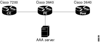
This section provides a configuration example of the feature for a simple network topology shown in Figure 1.
Figure 1 MPLS VPN Topology

Note ![]() The network addresses and telephone numbers used in the following configuration are examples only and will not work in an actual network configuration.
The network addresses and telephone numbers used in the following configuration are examples only and will not work in an actual network configuration.
Customer Edge (CE) Router
!
hostname oaktree02
enable secret 5 !1!35Fg$Ep4.D8JGpg7rKxQa49BF9/
!
ip subnet-zero
no ip domain-lookup
!
controller T1 5/0
!
controller T1 5/1
!
interface FastEthernet0/0
no ip address
no ip mroute-cache
duplex auto
speed auto
!
interface FastEthernet0/1
no ip address
no ip mroute-cache
shutdown
duplex auto
speed auto
!
interface Ethernet1/0
ip address 10.0.58.11 255.255.255.0
no ip mroute-cache
half-duplex
!
interface Ethernet1/1
ip address 50.0.0.2 255.0.0.0
no ip mroute-cache
half-duplex
!
interface Ethernet1/2
no ip address
no ip mroute-cache
shutdown
half-duplex
!
interface Ethernet1/3
no ip address
no ip mroute-cache
shutdown
half-duplex
!
interface Serial2/0
no ip address
no ip mroute-cache
shutdown
no fair-queue
serial restart-delay 0
!
interface Serial2/1
no ip address
no ip mroute-cache
shutdown
serial restart-delay 0
!
interface Serial2/2
no ip address
no ip mroute-cache
shutdown
serial restart-delay 0
!
interface Serial2/3
no ip address
no ip mroute-cache
shutdown
serial restart-delay 0
!
interface FastEthernet4/0
no ip address
no ip mroute-cache
shutdown
duplex auto
speed auto
!
ip classless
ip route 0.0.0.0 0.0.0.0 10.0.58.1
ip route 60.0.0.0 255.0.0.0 50.0.0.1
no ip http server
!
!
snmp-server manager
banner motd ^C AV-8B OAKTREE^C
alias exec r sh run
!
line con 0
exec-timeout 0 0
line aux 0
login
line vty 0 4
no login
!
end
Provider Edge (PE) Router
hostname pinetree02
!
aaa new-model
!
!
aaa authentication login con-log none
aaa authentication ppp default group radius
aaa authorization network default group radius
aaa session-id common
enable secret 5 $1$7KlA$xpC8l4dJCZogbzZvGUtFl/
!
username rubbertree02 password 0 Hello
ip subnet-zero
!
no ip domain-lookup
!
ip vrf yellow
rd 100:1
ip cef
virtual-profile aaa
isdn switch-type primary-5ess
!
controller T1 3/0
framing esf
linecode b8zs
pri-group timeslots 1-24
!
controller T1 3/1
framing esf
linecode b8zs
!
controller T1 3/2
framing esf
linecode b8zs
!
controller T1 3/3
framing esf
linecode b8zs
!
controller T1 3/4
framing esf
linecode b8zs
!
controller T1 3/5
framing esf
linecode b8zs
!
controller T1 3/6
framing esf
linecode b8zs
!
controller T1 3/7
framing esf
linecode b8zs
!
interface Loopback0
ip vrf forwarding yellow
ip address 70.0.0.1 255.0.0.0
!
interface FastEthernet1/0
no ip address
shutdown
duplex half
!
interface Ethernet2/0
ip address 10.0.58.3 255.255.255.0
duplex full
!
interface Ethernet2/1
ip vrf forwarding yellow
ip address 50.0.0.1 255.0.0.0
duplex half
!
interface Ethernet2/2
no ip address
shutdown
duplex half
!
interface Ethernet2/3
no ip address
shutdown
duplex half
!
interface Serial3/0:23
description phone# 555-3123
no ip address
encapsulation ppp
dialer rotary-group 0
dialer-group 1
isdn switch-type primary-5ess
ppp authentication chap
!
interface Serial4/0
no ip address
shutdown
no fair-queue
!
interface Dialer0
ip address negotiated
encapsulation ppp
dialer in-band
dialer map ip 60.0.0.12 vrf yellow name rubbertree02 5552171
dialer map ip 60.0.0.2 5552172
dialer-group 1
ppp authentication chap
!
ip classless
ip route 0.0.0.0 0.0.0.0 10.0.58.1
ip route 60.0.0.2 255.255.255.255 Dialer0
ip route vrf yellow 60.0.0.0 255.0.0.0 Dialer0 permanent
no ip http server
ip pim bidir-enable
!
ip director cache time 60
dialer-list 1 protocol ip permit
!
radius-server host 172.19.192.89 auth-port 1645 acct-port 1646 key rad123
radius-server retransmit 3
call rsvp-sync
!
no mgcp timer receive-rtcp
!
mgcp profile default
!
dial-peer cor custom
!
gatekeeper
shutdown
!
banner motd ^C F/A-18 PINETREE ^C
!
line con 0
exec-timeout 0 0
login authentication con-log
line aux 0
line vty 5 15
!
end
Peer Router
hostname rubbertree02
!
logging buffered 32000 debugging
enable secret 5 $1$RCKC$scgtdlaDzjSyUVAi7KK5Q.
enable password Windy
!
username pinetree02 password 0 Hello
!
ip subnet-zero
no ip domain-lookup
!
isdn switch-type basic-5ess
!
interface Ethernet0
ip address 10.0.58.9 255.255.255.0
no ip route-cache
!
interface BRI0
description phone# 555-2171
ip address 60.0.0.12 255.0.0.0
encapsulation ppp
no ip route-cache
dialer map ip 60.0.0.11 5553123
dialer map ip 60.0.0.2 5552172
dialer-group 1
isdn switch-type basic-5ess
isdn fast-rollover-delay 45
!
ip default-gateway 10.0.58.1
ip classless
ip route 0.0.0.0 0.0.0.0 10.0.58.1
ip route 50.0.0.0 255.0.0.0 70.0.0.1
no ip http server
!
dialer-list 1 protocol ip permit
no cdp run
banner motd ^C F-4B RUBBERTREE^C
!
line con 0
exec-timeout 0 0
line vty 0 4
password Windy
login
!
end
AAA Server User File
[aaa-serv]/usr/testing/bin> ./radiusd_1.16 -d . -a . -x
greentree-16 Password = "Hello", Expiration = "Dec 31 2005"
Service-Type = Framed-User,
Framed-Protocol = PPP
cisco-avpair = "lcp:interface-config=ip vrf forwarding yellow \nip
unnumbered Loopback0"
Additional References
Related Documents
|
|
|
|---|---|
MPLS |
Standards
|
|
|
|---|---|
No new or modified standards are supported by this feature, and support for existing standards has not been modified by this feature. |
— |
MIBs
RFCs
Technical Assistance
Feature Information for Dialing to Destinations with the Same IP Address
Table 1 lists the features in this module and provides links to specific configuration information.
Not all commands may be available in your Cisco IOS software release. For details on when support for specific commands was introduced, see the command reference documents.
Cisco IOS software images are specific to a Cisco IOS software release, a feature set, and a platform. Use Cisco Feature Navigator to find information about platform support and Cisco IOS software image support. Access Cisco Feature Navigator at http://www.cisco.com/go/fn. You must have an account on Cisco.com. If you do not have an account or have forgotten your username or password, click Cancel at the login dialog box and follow the instructions that appear.
Note ![]() Table 1 lists only the Cisco IOS software release that introduced support for a given feature in a given Cisco IOS software release train. Unless noted otherwise, subsequent releases of that Cisco IOS software release train also support that feature.
Table 1 lists only the Cisco IOS software release that introduced support for a given feature in a given Cisco IOS software release train. Unless noted otherwise, subsequent releases of that Cisco IOS software release train also support that feature.
|
|
|
|
|---|---|---|
Dialer Map VRF-Aware for MPLS VPNs |
12.2(8)T |
The Cisco IOS dialer software is "VRF-aware for an MPLS VPN," which means that it can distinguish between two destinations with the same IP address using information stored in the VRF. The following sections provide information about this feature: • • |

 Feedback