Feedback
Table Of Contents
Prerequisites for the EtherSwitch Network Module
Restrictions for the EtherSwitch Network Module
Information About the EtherSwitch Network Module
EtherSwitch Network Module: Benefits
Ethernet Switching in Cisco AVVID Architecture
Inline Power for Cisco IP Phones
Using the Spanning Tree Protocol with the EtherSwitch Network Module
Flow Control on Gigabit Ethernet Ports
IP Multicast Layer 3 Switching
Network Security with ACLs at Layer 2
Quality of Service for the EtherSwitch Network Module
How to Configure the EtherSwitch Network Module
VLAN Removal from the Database
Configuring VLAN Trunking Protocol
Configuring Spanning Tree on a VLAN
Verifying Spanning Tree on a VLAN
Configuring Layer 2 Interfaces
Interface Speed and Duplex Mode Guidelines
Configuring an Ethernet Interface as a Layer 2 Trunk
Configuring an Ethernet Interface as a Layer 2 Access
Configuring Separate Voice and Data VLANs
Voice Traffic and Voice VLAN ID (VVID) Using the EtherSwitch Network Module
Configuring a Single Voice and Data VLAN
Managing the EtherSwitch Network Module
IP Information Assigned to the Switch
Use of Ethernet Ports to Support Cisco IP Phones with Multiple Ports
Domain Name Mapping and DNS Configuration
Port Connection to a Cisco 7960 IP Phone
Inline Power on an EtherSwitch Network Module
Verifying Cisco Discovery Protocol
Configuring the MAC Table to Provide Port Security
Configuring 802.1x Authentication
802.1x Authentication Guidelines for the EtherSwitch Network Module
Enabling 802.1x Authentication
Configuring the Switch-to-RADIUS-Server Communication
Configuring 802.1x Parameters (Retransmissions and Timeouts)
Configuring Power Management on the Interfaces
Enabling Per-Port Storm Control
Configuring Layer 2 EtherChannels (Port-Channel Logical Interfaces)
Configuring Flow Control on Gigabit Ethernet Ports
Configuring Intrachassis Stacking
Configuring Switched Port Analyzer (SPAN)
Configuring Layer 3 Interfaces
Layer 3 Interface Support for the EtherSwitch Network Module
Enabling and Verifying IP Multicast Layer 3 Switching
IGMP Snooping on the EtherSwitch Network Module
IGMP Immediate-Leave Processing
Static Configuration of an Interface to Join a Multicast Group
Understanding the Default Fallback Bridging Configuration
Adjusting Spanning-Tree Parameters
Disabling the Spanning Tree on an Interface
Configuring Network Security with ACLs at Layer 2
Creating Standard and Extended IP ACLs
Including Comments About Entries in ACLs
Configuring a Numbered Standard ACL
Configuring a Numbered Extended ACL
Configuring a Named Standard ACL
Configuring a Named Extended ACL
Applying the ACL to an Interface
Configuring Quality of Service (QoS) on the EtherSwitch Network Module
Trust State on Ports and SVIs Within the QoS Domain
Configuring Classification Using Port Trust States
Classifying Traffic by Using ACLs
Classifying Traffic Using Class Maps
Classifying, Policing, and Marking Traffic Using Policy Maps
Configuring the CoS-to-DSCP Map
Configuring the DSCP-to-CoS Map
Configuration Examples for the EtherSwitch Network Module
Configuring Spanning Tree: Examples
Configuring Layer 2 Interfaces: Examples
Single Range Configuration: Example
Multiple Range Configuration: Example
Range Macro Definition: Example
Optional Interface Features: Example
Configuring an Ethernet Interface as a Layer 2 Trunk: Example
Configuring Voice and Data VLANs: Examples
Separate Voice and Data VLANs: Example
Single Subnet Configuration: Example
Ethernet Ports on IP Phones with Multiple Ports: Example
Configuring 802.1x Authentication: Examples
Enabling 802.1x Authentication: Example
Configuring the Switch-to-RADIUS-Server Communication: Example
Configuring 802.1x Parameters: Example
Configuring Storm-Control: Example
Configuring Layer 2 EtherChannels: Example
Layer 2 EtherChannels: Example
Removing an EtherChannel: Example
Configuring Flow Control on Gigabit Ethernet Ports: Example
Intrachassis Stacking: Example
Configuring Switched Port Analyzer (SPAN): Example
Configuring Layer 3 Interfaces: Example
Configuring Fallback Bridging: Examples
Creating a Bridge Group: Example
Adjusting Spanning Tree Parameters: Example
Disabling the Spanning Tree on an Interface: Example
Fallback Bridging with DLSW: Example
Configuring Network Security with ACLs at Layer 2: Examples
Creating Numbered Standard and Extended ACLs: Example
Creating Named Standard and Extended ACLs: Example
Including Comments About Entries in ACLs: Example
Applying the ACL to an Interface: Example
Displaying Standard and Extended ACLs: Example
Displaying Access Groups: Example
Configuring QoS on the EtherSwitch Network Module: Examples
Classifying Traffic by Using ACLs: Example
Classifying Traffic by Using Class Maps: Example
Classifying, Policing, and Marking Traffic by Using Policy Maps: Example
Configuring the CoS-to-DSCP Map: Example
Configuring the DSCP-to-CoS Map: Example
Displaying QoS Information: Example
Feature Information for EtherSwitch Network Module
EtherSwitch Network Module
This document explains how to configure the EtherSwitch Network Module. This network module is supported on Cisco 2600 series, Cisco 3600 series, and Cisco 3700 series routers. The EtherSwitch Network Module is a modular, high-density voice network module that provides Layer 2 switching across Ethernet ports. The EtherSwitch Network Module has sixteen 10/100 switched Ethernet ports with integrated inline power and QoS features that are designed to extend Cisco AVVID-based voice-over-IP (VoIP) networks to small branch offices.
Finding Feature Information
Your software release may not support all the features documented in this module. For the latest feature information and caveats, see the release notes for your platform and software release. To find information about the features documented in this module, and to see a list of the releases in which each feature is supported, see the "Feature Information for EtherSwitch Network Module" section.
Use Cisco Feature Navigator to find information about platform support and Cisco IOS and Catalyst OS software image support. To access Cisco Feature Navigator, go to http://www.cisco.com/go/cfn. An account on Cisco.com is not required.
Contents
•
Prerequisites for the EtherSwitch Network Module
•
•
•
•
•
Prerequisites for the EtherSwitch Network Module
The following are the prerequisites for the EtherSwitch Network Module:
•
•
In addition, complete the following tasks before configuring this feature:
•
For more information on IP routing, see the the "Configuring IP Routing Protocol-Independent Features" module in the Cisco IOS IP Routing: Protocol-Independent Configuration Guide.
•
For more information on setting up call agents, refer to the documentation that accompanies the call agents used in your network configuration.
Restrictions for the EtherSwitch Network Module
The following functions are not supported by the EtherSwitch Network Module:
•
•
•
•
•
•
•
•
•
•
•
•
•
•
•
•
•
Information About the EtherSwitch Network Module
To configure the EtherSwitch Network Module, you should understand the following concepts:
•
•
•
•
•
•
•
•
EtherSwitch Network Module: Benefits
•
•
•
•
•
•
The Interface Range Specification feature makes configuration easier for these reasons:
•
•
Ethernet Switching in Cisco AVVID Architecture
The EtherSwitch Network Module is designed to work as part of the Cisco Architecture for Voice, Video, and Integrated Data (AVVID) solution. The EtherSwitch Network Module has sixteen 10/100 switched Ethernet ports with integrated inline power and QoS features that allow for extending Cisco AVVID-based voice-over-IP (VoIP) networks to small branch offices.
The 16-port EtherSwitch Network Module has sixteen 10/100BASE-TX ports and an optional 10/100/1000BASE-T Gigabit Ethernet port. The 36-port EtherSwitch Network Module has thirty six 10/100BASE-TX ports and two optional 10/100/1000BASE-T Gigabit Ethernet ports. The gigabit Ethernet can be used as an uplink port to a server or as a stacking link to another 16- or 36-port EtherSwitch Network Module in the same system. The 36-port EtherSwitch Network Module requires a double-wide slot. An optional power module can also be added to provide inline power for IP telephones.
As an access gateway switch, the EtherSwitch Network Module can be deployed as a component of a centralized call-processing network using a centrally deployed Cisco CallManager (CCM). Instead of deploying and managing key systems or PBXs in small branch offices, applications are centrally located at the corporate headquarters or data center and are accessed via the IP WAN.
By default, the EtherSwitch Network Module provides the following settings with respect to Cisco AVVID:
•
•
•
•
VLANs
Virtual local-area networks (VLANs) are a group of end stations with a common set of requirements, independent of physical location. VLANs have the same attributes as a physical LAN but allow you to group end stations even if they are not located physically on the same LAN segment.
VLAN Trunk Protocol
VLAN Trunk Protocol (VTP) is a Layer 2 messaging protocol that maintains VLAN configuration consistency by managing the addition, deletion, and renaming of VLANs within a VTP domain. A VTP domain (also called a VLAN management domain) is made up of one or more switches that share the same VTP domain name and that are interconnected with trunks. VTP minimizes misconfigurations and configuration inconsistencies that can result in a number of problems, such as duplicate VLAN names, incorrect VLAN-type specifications, and security violations. Before you create VLANs, you must decide whether to use VTP in your network. With VTP, you can make configuration changes centrally on one or more switches and have those changes automatically communicated to all the other switches in the network.
VTP Domain
A VTP domain (also called a VLAN management domain) is made up of one or more interconnected switches that share the same VTP domain name. A switch can be configured to be in only one VTP domain. You make global VLAN configuration changes for the domain using either the command-line interface (CLI) or Simple Network Management Protocol (SNMP).
By default, the switch is in VTP server mode and is in an un-named domain state until the switch receives an advertisement for a domain over a trunk link or until you configure a management domain. You cannot create or modify VLANs on a VTP server until the management domain name is specified or learned.
If the switch receives a VTP advertisement over a trunk link, it inherits the management domain name and the VTP configuration revision number. The switch ignores advertisements with a different management domain name or an earlier configuration revision number.
If you configure the switch as VTP transparent, you can create and modify VLANs, but the changes affect only the individual switch.
When you make a change to the VLAN configuration on a VTP server, the change is propagated to all switches in the VTP domain. VTP advertisements are transmitted out all trunk connections using IEEE 802.1Q encapsulation.
VTP maps VLANs dynamically across multiple LAN types with unique names and internal index associations. Mapping eliminates excessive device administration required from network administrators.
VTP Modes
You can configure a switch to operate in any one of these VTP modes:
•
•
•
VTP Advertisements
Each switch in the VTP domain sends periodic advertisements out each trunk interface to a reserved multicast address. VTP advertisements are received by neighboring switches, which update their VTP and VLAN configurations as necessary.
The following global configuration information is distributed in VTP advertisements:
•
•
•
•
•
VTP Version 2
If you use VTP in your network, you must decide whether to use VTP version 1 or version 2. VTP version 2 supports the following features not supported in version 1:
Unrecognized Type-Length-Value (TLV) Support—A VTP server or client propagates configuration changes to its other trunks, even for TLVs it is not able to parse. The unrecognized TLV is saved in NVRAM.
Version-Dependent Transparent Mode—In VTP version 1, a VTP transparent switch inspects VTP messages for the domain name and version, and forwards a message only if the version and domain name match. Since only one domain is supported in the NM-16ESW software, VTP version 2 forwards VTP messages in transparent mode, without checking the version.
Consistency Checks—In VTP version 2, VLAN consistency checks (such as VLAN names and values) are performed only when you enter new information through the CLI or SNMP. Consistency checks are not performed when new information is obtained from a VTP message, or when information is read from NVRAM. If the digest on a received VTP message is correct, its information is accepted without consistency checks.
VTP Configuration Guidelines and Restrictions
Follow these guidelines and restrictions when implementing VTP in your network:
•
•
•
•
•
•
•
Inline Power for Cisco IP Phones
The EtherSwitch Network Module can supply inline power to a Cisco 7960 IP phone, if required. The Cisco 7960 IP phone can also be connected to an AC power source and supply its own power to the voice circuit. When the Cisco 7960 IP phone is supplying its own power, a EtherSwitch Network Module can forward IP voice traffic to and from the phone.
A detection mechanism on the EtherSwitch Network Module determines whether it is connected to a Cisco 7960 IP phone. If the switch senses that there is no power on the circuit, the switch supplies the power. If there is power on the circuit, the switch does not supply it.
You can configure the switch to never supply power to the Cisco 7960 IP phone and to disable the detection mechanism.
Using the Spanning Tree Protocol with the EtherSwitch Network Module
Spanning Tree Protocol (STP) is a Layer 2 link management protocol that provides path redundancy while preventing undesirable loops in the network. For a Layer 2 Ethernet network to function properly, only one active path can exist between any two stations. Spanning tree operation is transparent to end stations, which cannot detect whether they are connected to a single LAN segment or to a switched LAN of multiple segments.
The EtherSwitch Network Module uses STP (the IEEE 802.1D bridge protocol) on all VLANs. By default, a single instance of STP runs on each configured VLAN (provided that you do not manually disable STP). You can enable and disable STP on a per-VLAN basis.
When you create fault-tolerant internetworks, you must have a loop-free path between all nodes in a network. The spanning tree algorithm calculates the best loop-free path throughout a switched Layer 2 network. Switches send and receive spanning tree frames at regular intervals. The switches do not forward these frames but use the frames to construct a loop-free path.
Spanning Tree Protocol (STP) defines a tree with a root switch and a loop-free path from the root to all switches in the Layer 2 network. STP forces redundant data paths into a standby (blocked) state. If a network segment in the spanning tree fails and a redundant path exists, the spanning tree algorithm recalculates the spanning tree topology and activates the standby path.
When two ports on a switch are part of a loop, the spanning tree port priority and port path cost setting determine which port is put in the forwarding state and which port is put in the blocking state. The spanning tree port priority value represents the location of an interface in the network topology and how well located it is to pass traffic. The spanning tree port path cost value represents media speed.
Bridge Protocol Data Units
The stable active spanning tree topology of a switched network is determined by the following:
•
•
•
The Bridge Protocol Data Units (BPDU) are transmitted in one direction from the root switch, and each switch sends configuration BPDUs to communicate and compute the spanning tree topology. Each configuration BPDU contains the following minimal information:
•
•
•
•
•
•
When a switch transmits a BPDU frame, all switches connected to the LAN on which the frame is transmitted receive the BPDU. When a switch receives a BPDU, it does not forward the frame but instead uses the information in the frame to calculate a BPDU, and, if the topology changes, initiate a BPDU transmission.
A BPDU exchange results in the following:
•
•
•
•
•
•
For each VLAN, the switch with the highest bridge priority (the lowest numerical priority value) is elected as the root switch. If all switches are configured with the default priority (32768), the switch with the lowest MAC address in the VLAN becomes the root switch.
The spanning tree root switch is the logical center of the spanning tree topology in a switched network. All paths that are not needed to reach the root switch from anywhere in the switched network are placed in spanning tree blocking mode.
BPDUs contain information about the transmitting bridge and its ports, including bridge and MAC addresses, bridge priority, port priority, and path cost. Spanning tree uses this information to elect the root bridge and root port for the switched network, as well as the root port and designated port for each switched segment.
STP Timers
describes the STP timers that affect the entire spanning tree performance.
Spanning Tree Port States
Propagation delays can occur when protocol information passes through a switched LAN. As a result, topology changes can take place at different times and at different places in a switched network. When a Layer 2 interface changes directly from nonparticipation in the spanning tree topology to the forwarding state, it can create temporary data loops. Ports must wait for new topology information to propagate through the switched LAN before starting to forward frames. They must allow the frame lifetime to expire for frames that have been forwarded using the old topology.
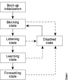
Each Layer 2 interface on a switch using spanning tree exists in one of the following five states:
•
•
•
•
•
A Layer 2 interface moves through these five states as follows:
•
•
•
•
•
Figure 1 illustrates how a port moves through the five stages.
Figure 1 STP Port States
Boot-up Initialization
When you enable spanning tree, every port in the switch, VLAN, or network goes through the blocking state and the transitory states of listening and learning at power up. If properly configured, each Layer 2 interface stabilizes to the forwarding or blocking state.
When the spanning tree algorithm places a Layer 2 interface in the forwarding state, the following process occurs:
1.
2.
3.
4.
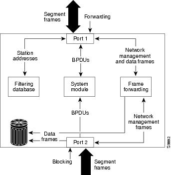
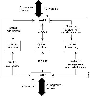
Blocking State
A Layer 2 interface in the blocking state does not participate in frame forwarding, as shown in Figure 2. After initialization, a BPDU is sent out to each Layer 2 interface in the switch. A switch initially assumes it is the root until it exchanges BPDUs with other switches. This exchange establishes which switch in the network is the root or root bridge. If only one switch is in the network, no exchange occurs, the forward delay timer expires, and the ports move to the listening state. A port always enters the blocking state following switch initialization.
Figure 2 Interface 2 in Blocking State
A Layer 2 interface in the blocking state performs as follows:
•
•
•
•
•
•
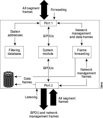
Listening State
The listening state is the first transitional state a Layer 2 interface enters after the blocking state. The Layer 2 interface enters this state when STP determines that the Layer 2 interface should participate in frame forwarding. Figure 3 shows a Layer 2 interface in the listening state.
Figure 3 Interface 2 in Listening State
A Layer 2 interface in the listening state performs as follows:
•
•
•
•
•
•
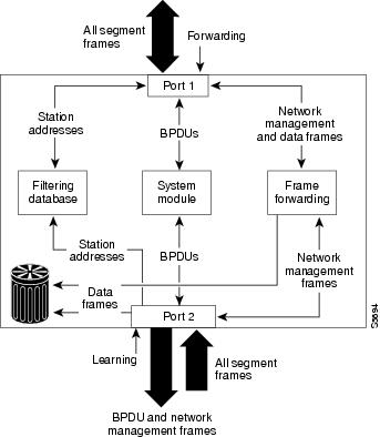
Learning State
A Layer 2 interface in the learning state prepares to participate in frame forwarding. The Layer 2 interface enters the learning state from the listening state. Figure 4 shows a Layer 2 interface in the learning state.
Figure 4 Interface 2 in Learning State
A Layer 2 interface in the learning state performs as follows:
•
•
•
•
•
•
Forwarding State
A Layer 2 interface in the forwarding state forwards frames, as shown in Figure 5. The Layer 2 interface enters the forwarding state from the learning state.
Figure 5 Interface 2 in Forwarding State
A Layer 2 interface in the forwarding state performs as follows:
•
•
•
•
•
•
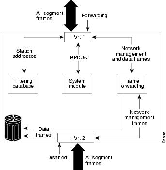
Disabled State
A Layer 2 interface in the disabled state does not participate in frame forwarding or spanning tree, as shown in Figure 6. A Layer 2 interface in the disabled state is virtually nonoperational.
Figure 6 Interface 2 in Disabled State
A disabled Layer 2 interface performs as follows:
•
•
•
•
•
MAC Address Allocation
The MAC address allocation manager has a pool of MAC addresses that are used as the bridge IDs for the VLAN spanning trees. In Table 2 you can view the number of VLANs allowed for each platform.
Table 2 Number of VLANs Allowed by Platform
Cisco 3640 or higher
64 VLANs
Cisco 2600
32 VLANs
MAC addresses are allocated sequentially, with the first MAC address in the range assigned to VLAN 1, the second MAC address in the range assigned to VLAN 2, and so forth.
For example, if the MAC address range is 00-e0-1e-9b-2e-00 to 00-e0-1e-9b-31-ff, the VLAN 1 bridge ID is 00-e0-1e-9b-2e-00, the VLAN 2 bridge ID is 00-e0-1e-9b-2e-01, the VLAN 3 bridge ID is 00-e0-1e-9b-2e-02, and so forth.
Default Spanning Tree Configuration
Table 3 shows the default Spanning Tree configuration values.
Spanning Tree Port Priority
In the event of a loop, spanning tree considers port priority when selecting an interface to put into the forwarding state. You can assign higher priority values to interfaces that you want spanning tree to select first, and lower priority values to interfaces that you want spanning tree to select last. If all interfaces have the same priority value, spanning tree puts the interface with the lowest interface number in the forwarding state and blocks other interfaces. The possible priority range is 0 to 255, configurable in increments of 4 (the default is 128).
Cisco IOS software uses the port priority value when the interface is configured as an access port and uses VLAN port priority values when the interface is configured as a trunk port.
Spanning Tree Port Cost
The spanning tree port path cost default value is derived from the media speed of an interface. In the event of a loop, spanning tree considers port cost when selecting an interface to put into the forwarding state. You can assign lower cost values to interfaces that you want spanning tree to select first and higher cost values to interfaces that you want spanning tree to select last. If all interfaces have the same cost value, spanning tree puts the interface with the lowest interface number in the forwarding state and blocks other interfaces.
The possible cost range is 0 to 65535 (the default is media-specific).
Spanning tree uses the port cost value when the interface is configured as an access port and uses VLAN port cost values when the interface is configured as a trunk port.
BackboneFast
BackboneFast is initiated when a root port or blocked port on a switch receives inferior BPDUs from its designated bridge. An inferior BPDU identifies one switch as both the root bridge and the designated bridge. When a switch receives an inferior BPDU, it means that a link to which the switch is not directly connected (an indirect link) has failed (that is, the designated bridge has lost its connection to the root switch). Under STP rules, the switch ignores inferior BPDUs for the configured maximum aging time specified by the spanning-tree max-age global configuration command.
The switch tries to determine if it has an alternate path to the root switch. If the inferior BPDU arrives on a blocked port, the root port and other blocked ports on the switch become alternate paths to the root switch. (Self-looped ports are not considered alternate paths to the root switch.) If the inferior BPDU arrives on the root port, all blocked ports become alternate paths to the root switch. If the inferior BPDU arrives on the root port and there are no blocked ports, the switch assumes that it has lost connectivity to the root switch, causes the maximum aging time on the root to expire, and becomes the root switch according to normal STP rules.
If the switch has alternate paths to the root switch, it uses these alternate paths to transmit a new kind of Protocol Data Unit (PDU) called the Root Link Query PDU. The switch sends the Root Link Query PDU on all alternate paths to the root switch. If the switch determines that it still has an alternate path to the root, it causes the maximum aging time on the ports on which it received the inferior BPDU to expire. If all the alternate paths to the root switch indicate that the switch has lost connectivity to the root switch, the switch causes the maximum aging times on the ports on which it received an inferior BPDU to expire. If one or more alternate paths can still connect to the root switch, the switch makes all ports on which it received an inferior BPDU its designated ports and moves them out of the blocking state (if they were in the blocking state), through the listening and learning states, and into the forwarding state.
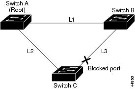
Figure 7 shows an example topology with no link failures. Switch A, the root switch, connects directly to Switch B over link L1 and to Switch C over link L2. The interface on Switch C that connects directly to Switch B is in the blocking state.
Figure 7 BackboneFast Example Before Indirect Link Failure
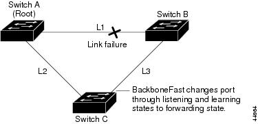
If link L1 fails, Switch C cannot detect this failure because it is not connected directly to link L1. However, because Switch B is directly connected to the root switch over L1, it detects the failure, elects itself the root, and begins sending BPDUs to Switch C, identifying itself as the root. When Switch C receives the inferior BPDUs from Switch B, Switch C assumes that an indirect failure has occurred. At that point, BackboneFast allows the blocked port on Switch C to move immediately to the listening state without waiting for the maximum aging time for the port to expire. BackboneFast then changes the interface on Switch C to the forwarding state, providing a path from Switch B to Switch A. This switchover takes approximately 30 seconds, twice the Forward Delay time if the default Forward Delay time of 15 seconds is set. Figure 8 shows how BackboneFast reconfigures the topology to account for the failure of link L1.
Figure 8 BackboneFast Example After Indirect Link Failure
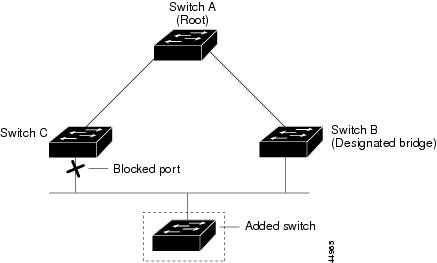
If a new switch is introduced into a shared-medium topology as shown in Figure 9, BackboneFast is not activated because the inferior BPDUs did not come from the recognized designated bridge (Switch B). The new switch begins sending inferior BPDUs that say it is the root switch. However, the other switches ignore these inferior BPDUs, and the new switch learns that Switch B is the designated bridge to Switch A, the root switch.
Figure 9 Adding a Switch in a Shared-Medium Topology
Layer 2 Ethernet Switching
EtherSwitch Network Modules support simultaneous, parallel connections between Layer 2 Ethernet segments. Switched connections between Ethernet segments last only for the duration of the packet. New connections can be made between different segments for the next packet.
The EtherSwitch Network Module solves congestion problems caused by high-bandwidth devices and a large number of users by assigning each device (for example, a server) to its own 10-, 100-, or 1000-Mbps segment. Because each Ethernet interface on the switch represents a separate Ethernet segment, servers in a properly configured switched environment achieve full access to the bandwidth.
Because collisions are a major bottleneck in Ethernet networks, an effective solution is full-duplex communication. Normally, Ethernet operates in half-duplex mode, which means that stations can either receive or transmit. In full-duplex mode, two stations can transmit and receive at the same time. When packets can flow in both directions simultaneously, effective Ethernet bandwidth doubles to 20 Mbps for 10-Mbps interfaces and to 200 Mbps for Fast Ethernet interfaces.
Switching Frames Between Segments
Each Ethernet interface on an EtherSwitch Network Module can connect to a single workstation or server, or to a hub through which workstations or servers connect to the network.
On a typical Ethernet hub, all ports connect to a common backplane within the hub, and the bandwidth of the network is shared by all devices attached to the hub. If two stations establish a session that uses a significant level of bandwidth, the network performance of all other stations attached to the hub is degraded.
To reduce degradation, the switch treats each interface as an individual segment. When stations on different interfaces need to communicate, the switch forwards frames from one interface to the other at wire speed to ensure that each session receives full bandwidth.
To switch frames between interfaces efficiently, the switch maintains an address table. When a frame enters the switch, it associates the MAC address of the sending station with the interface on which it was received.
Building the Address Table
The EtherSwitch Network Module builds the address table by using the source address of the frames received. When the switch receives a frame for a destination address not listed in its address table, it floods the frame to all interfaces of the same virtual local-area network (VLAN) except the interface that received the frame. When the destination station replies, the switch adds its relevant source address and interface ID to the address table. The switch then forwards subsequent frames to a single interface without flooding to all interfaces. The address table can store at least 8,191 address entries without flooding any entries. The switch uses an aging mechanism, defined by a configurable aging timer; so if an address remains inactive for a specified number of seconds, it is removed from the address table.
Note
VLAN Trunks
A trunk is a point-to-point link between one or more Ethernet switch interfaces and another networking device such as a router or a switch. Trunks carry the traffic of multiple VLANs over a single link and allow you to extend VLANs across an entire network and supports only one encapsulation on all Ethernet interfaces: 802.1Q-802.1Q is an industry-standard trunking encapsulation. You can configure a trunk on a single Ethernet interface or on an EtherChannel bundle.
Layer 2 Interface Modes
When you connect a Cisco switch to a device other than a Cisco device through an 802.1Q trunk, the Cisco switch combines the spanning tree instance of the VLAN trunk with the spanning tree instance of the other 802.1Q switch. However, spanning tree information for each VLAN is maintained by Cisco switches separated by a cloud of 802.1Q switches that are not Cisco switches. The 802.1Q cloud separating the Cisco switches that is not Cisco devised, is treated as a single trunk link between the switches.
Make sure that the native VLAN for an 802.1Q trunk is the same on both ends of the trunk link. If the VLAN on one end of the trunk is different from the VLAN on the other end, spanning tree loops might result. Inconsistencies detected by a Cisco switch mark the line as broken and block traffic for the specific VLAN.
Disabling spanning tree on the VLAN of an 802.1Q trunk without disabling spanning tree on every VLAN in the network can potentially cause spanning tree loops. Cisco recommends that you leave spanning tree enabled on the VLAN of an 802.1Q trunk or that you disable spanning tree on every VLAN in the network. Make sure that your network is loop-free before disabling spanning tree.
Layer 2 Interface Configuration Guidelines and Restrictions
Cisco Discovery Protocol
Cisco Discovery Protocol (CDP) is a protocol that runs over Layer 2 (the data link layer) on all Cisco routers, bridges, access servers, and switches. CDP allows network management applications to discover Cisco devices that are neighbors of already known devices, in particular, neighbors running lower-layer, transparent protocols. With CDP, network management applications can learn the device type and the SNMP agent address of neighboring devices. This feature enables applications to send SNMP queries to neighboring devices.
CDP runs on all LAN and WAN media that support Subnetwork Access Protocol (SNAP). Each CDP-configured device sends periodic messages to a multicast address. Each device advertises at least one address at which it can receive SNMP messages. The advertisements also contain the time-to-live, or hold-time information, which indicates the length of time a receiving device should hold CDP information before discarding it.
Port Security
You can use port security to block input to an Ethernet, Fast Ethernet, or Gigabit Ethernet port when the MAC address of the station attempting to access the port is different from any of the MAC addresses specified for that port. Alternatively, you can use port security to filter traffic destined to or received from a specific host based on the host MAC address.
802.1x Authentication
This section describes how to configure IEEE 802.1x port-based authentication to prevent unauthorized devices (clients) from gaining access to the network. As LANs extend to hotels, airports, and corporate lobbies, insecure environments could be created.
Understanding 802.1x Port-Based Authentication
The IEEE 802.1x standard defines a client/server-based access control and authentication protocol that restricts unauthorized devices from connecting to a LAN through publicly accessible ports. The authentication server authenticates each client connected to a switch port before making available any services offered by the switch or the LAN.
Until the client is authenticated, 802.1x access control allows only Extensible Authentication Protocol over LAN (EAPOL) traffic through the port to which the client is connected. After authentication is successful, normal traffic can pass through the port.
Device Roles
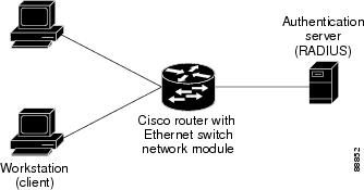
With 802.1x port-based authentication, the devices in the network have specific roles as shown in Figure 10.
Figure 10 802.1x Device Roles
•
•
•
When the switch receives EAPOL frames and relays them to the authentication server, the Ethernet header is stripped and the remaining EAP frame is reencapsulated in the RADIUS format. The EAP frames are not modified or examined during encapsulation, and the authentication server must support EAP within the native frame format. When the switch receives frames from the authentication server, the server's frame header is removed, leaving the EAP frame, which is then encapsulated for Ethernet and sent to the client.
The devices that can act as intermediaries include the Catalyst 3550 multilayer switch, Catalyst 2950 switch, or a wireless access point. These devices must be running software that supports the RADIUS client and 802.1x.
Authentication Initiation and Message Exchange
The switch or the client can initiate authentication. If you enable authentication on a port by using the dot1x port-control auto interface configuration command, the switch must initiate authentication when it determines that the port link state changes from down to up. It then sends an EAP-request/identity frame to the client to request its identity (typically, the switch sends an initial identity/request frame followed by one or more requests for authentication information). Upon receipt of the frame, the client responds with an EAP-response/identity frame.
However, if during bootup, the client does not receive an EAP-request/identity frame from the switch, the client can initiate authentication by sending an EAPOL-start frame, which prompts the switch to request the client's identity.
Note
When the client supplies its identity, the switch begins its role as the intermediary, passing EAP frames between the client and the authentication server until authentication succeeds or fails. If the authentication succeeds, the switch port becomes authorized.
The specific exchange of EAP frames depends on the authentication method being used. Figure 11 shows a message exchange initiated by the client using the One-Time-Password (OTP) authentication method with a RADIUS server.
Figure 11 Message Exchange
Ports in Authorized and Unauthorized States
The switch port state determines whether or not the client is granted access to the network. The port starts in the unauthorized state. While in this state, the port disallows all ingress and egress traffic except for 802.1x packets. When a client is successfully authenticated, the port changes to the authorized state, allowing all traffic for the client to flow normally.
If a client that does not support 802.1x is connected to an unauthorized 802.1x port, the switch requests the client's identity. In this situation, the client does not respond to the request, the port remains in the unauthorized state, and the client is not granted access to the network.
In contrast, when an 802.1x-enabled client connects to a port that is not running 802.1x, the client initiates the authentication process by sending the EAPOL-start frame. When no response is received, the client sends the request for a fixed number of times. Because no response is received, the client begins sending frames as if the port is in the authorized state.
If the client is successfully authenticated (receives an Accept frame from the authentication server), the port state changes to authorized, and all frames from the authenticated client are allowed through the port. If the authentication fails, the port remains in the unauthorized state, but authentication can be retried. If the authentication server cannot be reached, the switch can retransmit the request. If no response is received from the server after the specified number of attempts, authentication fails, and network access is not granted.
When a client logs off, it sends an EAPOL-logoff message, causing the switch port to change to the unauthorized state.
If the link state of a port changes from up to down, or if an EAPOL-logoff frame is received, the port returns to the unauthorized state.
Supported Topologies
The 802.1x port-based authentication is supported in two topologies:
•
•
In a point-to-point configuration (see Figure 10), only one client can be connected to the 802.1x-enabled switch port. The switch detects the client when the port link state changes to the up state. If a client leaves or is replaced with another client, the switch changes the port link state to down, and the port returns to the unauthorized state.
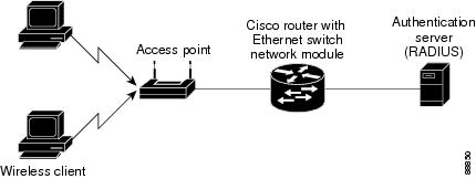
Figure 12 shows 802.1x-port-based authentication in a wireless LAN. The 802.1x port is configured as a multiple-host port that becomes authorized as soon as one client is authenticated. When the port is authorized, all other hosts indirectly attached to the port are granted access to the network. If the port becomes unauthorized (reauthentication fails or an EAPOL-logoff message is received), the switch denies access to the network to all of the attached clients. In this topology, the wireless access point is responsible for authenticating the clients attached to it, and the wireless access point acts as a client to the switch.
Figure 12 Wireless LAN Example
Storm Control
A traffic storm occurs when packets flood the LAN, creating excessive traffic and degrading network performance. Errors in the protocol-stack implementation or in the network configuration can cause a storm. Storm control can be implemented globally or on a per-port basis. Global storm control and per-port storm control cannot be enabled at the same time.
Global Storm Control
Global storm control prevents switchports on a LAN from being disrupted by a broadcast, multicast, or unicast storm on one of the interfaces. Global storm control monitors incoming traffic statistics over a time period and compares the measurement with a predefined suppression level threshold. The threshold represents the percentage of the total available bandwidth of the port. If the threshold of a traffic type is reached, further traffic of that type is suppressed until the incoming traffic falls below the threshold level. Global storm control is disabled by default.
The switch supports global storm control for broadcast, multicast, and unicast traffic. This example of broadcast suppression can also be applied to multicast and unicast traffic.
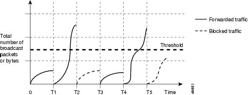
The graph in Figure 13 shows broadcast traffic patterns on an interface over a given period of time. In this example, the broadcast traffic exceeded the configured threshold between time intervals T1 and T2 and between T4 and T5. When the amount of specified traffic exceeds the threshold, all traffic of that kind is dropped. Therefore, broadcast traffic is blocked during those intervals. At the next time interval, if broadcast traffic does not exceed the threshold, it is again forwarded.
Figure 13 Broadcast Suppression Example
When global storm control is enabled, the switch monitors packets passing from an interface to the switching bus and determines if the packet is unicast, multicast, or broadcast. The switch monitors the number of broadcast, multicast, or unicast packets received within the 1-second time interval, and when a threshold for one type of traffic is reached, that type of traffic is dropped. This threshold is specified as a percentage of total available bandwidth that can be used by broadcast (multicast or unicast) traffic.
The combination of broadcast suppression threshold numbers and the 1-second time interval control the way the suppression algorithm works. A higher threshold allows more packets to pass through. A threshold value of 100 percent means that no limit is placed on the traffic.
Note
The switch continues to monitor traffic on the port, and when the utilization level is below the threshold level, the type of traffic that was dropped is forwarded again.
Per-Port Storm Control
A packet storm occurs when a large number of broadcast, unicast, or multicast packets are received on a port. Forwarding these packets can cause the network to slow down or to time out. By default, per-port storm control is disabled.
Per-port storm control uses rising and falling thresholds to block and then restore the forwarding of broadcast, unicast, or multicast packets. You can also set the switch to shut down the port when the rising threshold is reached.
Per-port storm control uses a bandwidth-based method to measure traffic activity. The thresholds are expressed as a percentage of the total available bandwidth that can be used by the broadcast, multicast, or unicast traffic.
The rising threshold is the percentage of total available bandwidth associated with multicast, broadcast, or unicast traffic before forwarding is blocked. The falling threshold is the percentage of total available bandwidth below which the switch resumes normal forwarding. In general, the higher the level, the less effective the protection against broadcast storms.
EtherChannel
EtherChannel bundles up to eight individual Ethernet links into a single logical link that provides bandwidth of up to 1600 Mbps (Fast EtherChannel full duplex) between the network module and another switch or host.
An EtherSwitch Network Module system supports a maximum of six EtherChannels. All interfaces in each EtherChannel must have the same speed duplex and mode.
Load Balancing
EtherChannel balances traffic load across the links in a channel by reducing part of the binary pattern formed from the addresses in the frame to a numerical value that selects one of the links in the channel.
EtherChannel load balancing can use MAC addresses or IP addresses; either source or destination or both source and destination. The selected mode applies to all EtherChannels configured on the switch.
Use the option that provides the greatest variety in your configuration. For example, if the traffic on a channel is going only to a single MAC address, using the destination MAC address always chooses the same link in the channel; using source addresses or IP addresses may result in better load balancing.
EtherChannel Configuration Guidelines and Restrictions
If improperly configured, some EtherChannel interfaces are disabled automatically to avoid network loops and other problems. Follow these guidelines and restrictions to avoid configuration problems:
•
•
•
•
For Layer 2 EtherChannels:
•
An EtherChannel supports the same allowed range of VLANs on all interfaces in a trunking Layer 2 EtherChannel. If the allowed range of VLANs is not the same, the interfaces do not form an EtherChannel.
Interfaces with different Spanning Tree Protocol (STP) port path costs can form an EtherChannel as long they are otherwise compatibly configured. Setting different STP port path costs does not, by itself, make interfaces incompatible for the formation of an EtherChannel.
After you configure an EtherChannel, configuration that you apply to the port-channel interface affects the EtherChannel.
Flow Control on Gigabit Ethernet Ports
Flow control is a feature that Gigabit Ethernet ports use to inhibit the transmission of incoming packets. If a buffer on a Gigabit Ethernet port runs out of space, the port transmits a special packet that requests remote ports to delay sending packets for a period of time. This special packet is called a pause frame. The send and receive keywords of the set port flowcontrol command are used to specify the behavior of the pause frames.
Intrachassis Stacking
Multiple switch modules may be installed simultaneously by connecting the Gigabit Ethernet (GE) ports of the EtherSwitch Network Module. This connection sustains a line-rate traffic similar to the switch fabric found in Cisco Catalyst switches and forms a single VLAN consisting of all ports in multiple EtherSwitch Network Modules. The stacking port must be configured for multiple switch modules to operate correctly in the same chassis.
•
•
Switched Port Analyzer
Switched Port Analyzer Session
A Switched Port Analyzer (SPAN) session is an association of a destination interface with a set of source interfaces. You configure SPAN sessions using parameters that specify the type of network traffic to monitor. SPAN sessions allow you to monitor traffic on one or more interfaces and to send either ingress traffic, egress traffic, or both to one destination interface. You can configure one SPAN session with separate or overlapping sets of SPAN source interfaces or VLANs. Only switched interfaces can be configured as SPAN sources or destinations on the same network module.
SPAN sessions do not interfere with the normal operation of the switch. You can enable or disable SPAN sessions with command-line interface (CLI) or SNMP commands. When enabled, a SPAN session might become active or inactive based on various events or actions, and this would be indicated by a syslog message. The show monitor session command displays the operational status of a SPAN session.
A SPAN session remains inactive after system power-up until the destination interface is operational.
Destination Interface
A destination interface (also called a monitor interface) is a switched interface to which SPAN sends packets for analysis. You can have one SPAN destination interface. Once an interface becomes an active destination interface, incoming traffic is disabled. You cannot configure a SPAN destination interface to receive ingress traffic. The interface does not forward any traffic except that required for the SPAN session.
An interface configured as a destination interface cannot be configured as a source interface. EtherChannel interfaces cannot be SPAN destination interfaces.
Specifying a trunk interface as a SPAN destination interface stops trunking on the interface.
Source Interface
A source interface is an interface monitored for network traffic analysis. One or more source interfaces can be monitored in a single SPAN session with user-specified traffic types (ingress, egress, or both) applicable for all the source interfaces.
You can configure source interfaces in any VLAN. You can configure EtherChannel as source interfaces, which means that all interfaces in the specified VLANs are source interfaces for the SPAN session.
Trunk interfaces can be configured as source interfaces and mixed with nontrunk source interfaces; however, the destination interface never encapsulates.
Traffic Types
Ingress SPAN (Rx) copies network traffic received by the source interfaces for analysis at the destination interface. Egress SPAN (Tx) copies network traffic transmitted from the source interfaces. Specifying the configuration option both copies network traffic received and transmitted by the source interfaces to the destination interface.
SPAN Traffic
Network traffic, including multicast, can be monitored using SPAN. Multicast packet monitoring is enabled by default. In some SPAN configurations, multiple copies of the same source packet are sent to the SPAN destination interface. For example, a bidirectional (both ingress and egress) SPAN session is configured for sources a1 and a2 to a destination interface d1. If a packet enters the switch through a1 and gets switched to a2, both incoming and outgoing packets are sent to destination interface d1; both packets would be the same (unless a Layer-3 rewrite had occurred, in which case the packets would be different).
Note
SPAN Configuration Guidelines and Restrictions
Follow these guidelines and restrictions when configuring SPAN:
•
•
•
•
•
•
•
•
•
•
•
•
•
Switched Virtual Interface
A switch virtual interface (SVI) represents a VLAN of switch ports as one interface to the routing or bridging function in the system. Only one SVI can be associated with a VLAN, but it is necessary to configure an SVI for a VLAN only when you wish to route between VLANs, fallback-bridge nonroutable protocols between VLANs, or to provide IP host connectivity to the switch. By default, an SVI is created for the default VLAN (VLAN 1) to permit remote switch administration. Additional SVIs must be explicitly configured. You can configure routing across SVIs.
SVIs are created the first time that you enter the vlan interface configuration command for a VLAN interface. The VLAN corresponds to the VLAN tag associated with data frames on an ISL or 802.1Q encapsulated trunk or the VLAN ID configured for an access port. Configure a VLAN interface for each VLAN for which you want to route traffic, and assign it an IP address.
SVIs support routing protocol and bridging configurations. For more information about configuring IP routing across SVIs, see the "Enabling and Verifying IP Multicast Layer 3 Switching" section.
Routed Ports
A routed port is a physical port that acts like a port on a router; it does not have to be connected to a router. A routed port is not associated with a particular VLAN, as is an access port. A routed port behaves like a regular router interface, except that it does not support subinterfaces. Routed ports can be configured with a Layer 3 routing protocol.
Configure routed ports by putting the interface into Layer 3 mode with the no switchport interface configuration command. Then assign an IP address to the port, enable routing, and assign routing protocol characteristics by using the ip routing and router protocol global configuration commands.
Caution
The number of routed ports and SVIs that you can configure is not limited by software; however, the interrelationship between this number and the number of other features being configured might have an impact on CPU utilization because of hardware limitations.
Routed ports support only Cisco Express Forwarding (CEF) switching (IP fast switching is not supported).
IP Multicast Layer 3 Switching
The maximum number of configured VLANs must be less than or equal to 242. The maximum number of multicast groups is related to the maximum number of VLANs. The number of VLANs is determined by multiplying the number of VLANs by the number of multicast groups. For example, the maximum number for 10 VLANs and 20 groups would be 200, under the 242 limit. This feature also provides support for Protocol Independent Multicast (PIM) sparse mode/dense mode/sparse-dense mode.
IGMP Snooping
Internet Group Management Protocol (IGMP) snooping constrains the flooding of multicast traffic by dynamically configuring the interfaces so that multicast traffic is forwarded only to those interfaces associated with IP multicast devices. The LAN switch snoops on the IGMP traffic between the host and the router and keeps track of multicast groups and member ports. When the switch receives an IGMP join report from a host for a particular multicast group, the switch adds the host port number to the associated multicast forwarding table entry. When it receives an IGMP Leave Group message from a host, it removes the host port from the table entry. After it relays the IGMP queries from the multicast router, it deletes entries periodically if it does not receive any IGMP membership reports from the multicast clients.
When IGMP snooping is enabled, the multicast router sends out periodic IGMP general queries to all VLANs. The switch responds to the router queries with only one join request per MAC multicast group, and the switch creates one entry per VLAN in the Layer 2 forwarding table for each MAC group from which it receives an IGMP join request. All hosts interested in this multicast traffic send join requests and are added to the forwarding table entry.
Layer 2 multicast groups learned through IGMP snooping are dynamic. However, you can statically configure MAC multicast groups by using the ip igmp snooping vlan static command. If you specify group membership for a multicast group address statically, your setting supersedes any automatic manipulation by IGMP snooping. Multicast group membership lists can consist of both user-defined and IGMP snooping-learned settings.
EtherSwitch Network Modules support a maximum of 255 IP multicast groups and support both IGMP version 1 and IGMP version 2.
If a port spanning-tree, a port group, or a VLAN ID change occurs, the IGMP snooping-learned multicast groups from this port on the VLAN are deleted.
In the IP multicast-source-only environment, the switch learns the IP multicast group from the IP multicast data stream and only forwards traffic to the multicast router ports.
Immediate-Leave Processing
IGMP snooping Immediate-Leave processing allows the switch to remove an interface that sends a leave message from the forwarding table without first sending out MAC-based general queries to the interface. The VLAN interface is pruned from the multicast tree for the multicast group specified in the original leave message. Immediate-Leave processing ensures optimal bandwidth management for all hosts on a switched network, even when multiple multicast groups are in use simultaneously.
Note
Setting the Snooping Method
Multicast-capable router ports are added to the forwarding table for every IP multicast entry. The switch learns of such ports through one of these methods:
•
•
You can configure the switch to snoop on PIM/Distance Vector Multicast Routing Protocol (PIM/DVMRP) packets. By default, the switch snoops on PIM/DVMRP packets on all VLANs. To learn of multicast router ports through PIM-DVMRP packets, use the ip igmp snooping vlan vlan-id mrouter learn pim-dvmrp interface configuration command.
Joining a Multicast Group
When a host connected to the switch wants to join an IP multicast group, it sends an IGMP join message, specifying the IP multicast group it wants to join. When the switch receives this message, it adds the port to the IP multicast group port address entry in the forwarding table.
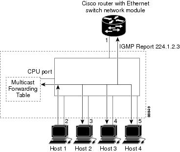
Refer to Figure 14. Host 1 wants to join multicast group 224.1.2.3 and send a multicast message of an unsolicited IGMP membership report (IGMP join message) to the group with the equivalent MAC destination address of 0100.5E01.0203. The switch recognizes IGMP packets and forwards them to the CPU. When the CPU receives the IGMP multicast report by Host 1, the CPU uses the information to set up a multicast forwarding table entry as shown in Table 5 that includes the port numbers of Host 1 and the router.
Figure 14 Initial IGMP Join Message
Table 5 IP Multicast Forwarding Table
0100.5e01.0203
!IGMP
1, 2
Note that the switch architecture allows the CPU to distinguish IGMP information packets from other packets for the multicast group. The switch recognizes the IGMP packets through its filter engine. This prevents the CPU from becoming overloaded with multicast frames.
The entry in the multicast forwarding table tells the switching engine to send frames addressed to the 0100.5E01.0203 multicast MAC address that are not IGMP packets (!IGMP) to the router and to the host that has joined the group.
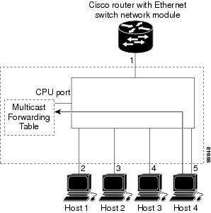
If another host (for example, Host 4) sends an IGMP join message for the same group (Figure 15), the CPU receives that message and adds the port number of Host 4 to the multicast forwarding table as shown in Table 6.
Figure 15 Second Host Joining a Multicast Group
Table 6 Updated Multicast Forwarding Table
0100.5e01.0203
!IGMP
1, 2, 5
Leaving a Multicast Group
The router sends periodic IP multicast general queries, and the switch responds to these queries with one join response per MAC multicast group. As long as at least one host in the VLAN needs multicast traffic, the switch responds to the router queries, and the router continues forwarding the multicast traffic to the VLAN. The switch only forwards IP multicast group traffic to those hosts listed in the forwarding table for that IP multicast group.
When hosts need to leave a multicast group, they can either ignore the periodic general-query requests sent by the router, or they can send a leave message. When the switch receives a leave message from a host, it sends out a group-specific query to determine if any devices behind that interface are interested in traffic for the specific multicast group. If, after a number of queries, the router processor receives no reports from a VLAN, it removes the group for the VLAN from its multicast forwarding table.
Fallback Bridging
With fallback bridging, the switch bridges together two or more VLANs or routed ports, essentially connecting multiple VLANs within one bridge domain. Fallback bridging forwards traffic that the multilayer switch does not route and forwards traffic belonging to a nonroutable protocol such as DECnet.
Fallback bridging does not allow the spanning trees from the VLANs being bridged to collapse; each VLAN has its own Spanning Tree Protocol (STP) instance and a separate spanning tree, called the VLAN-bridge spanning tree, which runs on top of the bridge group to prevent loops.
A VLAN bridge domain is represented using the switch virtual interface (SVI). A set of SVIs and routed ports (which do not have any VLANs associated with them) can be configured to form a bridge group.
Recall that an SVI represents a VLAN of switch ports as one interface to the routing or bridging function in the system. Only one SVI can be associated with a VLAN, and it is only necessary to configure an SVI for a VLAN when you want to route between VLANs, to fallback-bridge nonroutable protocols between VLANs, or to provide IP host connectivity to the switch. A routed port is a physical port that acts like a port on a router, but it is not connected to a router. A routed port is not associated with a particular VLAN, does not support subinterfaces, but behaves like a normal routed interface.
A bridge group is an internal organization of network interfaces on a switch. Bridge groups cannot be used to identify traffic switched within the bridge group outside the switch on which they are defined. Bridge groups on the same switch function as distinct bridges; that is, bridged traffic and bridge protocol data units (BPDUs) cannot be exchanged between different bridge groups on a switch. An interface can be a member of only one bridge group. Use a bridge group for each separately bridged (topologically distinct) network connected to the switch.
The purpose of placing network interfaces into a bridge group is twofold:
•
•
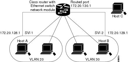
Figure 16 shows a fallback bridging network example. The multilayer switch has two interfaces configured as SVIs with different assigned IP addresses and attached to two different VLANs. Another interface is configured as a routed port with its own IP address. If all three of these ports are assigned to the same bridge group, non-IP protocol frames can be forwarded among the end stations connected to the switch.
Figure 16 Fallback Bridging Network Example
Network Security with ACLs at Layer 2
Network security on your EtherSwitch Network Module can be implemented using access control lists (ACLs), which are also referred to in commands and tables as access lists.
Understanding ACLs
Packet filtering can limit network traffic and restrict network use by certain users or devices. ACLs can filter traffic as it passes through a switch and permit or deny packets from crossing specified interfaces. An ACL is a sequential collection of permit and deny conditions that apply to packets. When a packet is received on an interface, the switch compares the fields in the packet against any applied ACLs to verify that the packet has the required permissions to be forwarded, based on the criteria specified in the access lists. The switch tests the packet against the conditions in an access list one by one. The first match determines whether the switch accepts or rejects the packet. Because the switch stops testing conditions after the first match, the order of conditions in the list is critical. If no conditions match, the switch rejects the packet. If there are no restrictions, the switch forwards the packet; otherwise, the switch drops the packet.
You configure access lists on a Layer 2 switch to provide basic security for your network. If you do not configure ACLs, all packets passing through the switch could be allowed onto all parts of the network. You can use ACLs to control which hosts can access different parts of a network or to decide which types of traffic are forwarded or blocked at switch interfaces. For example, you can allow e-mail traffic to be forwarded but not Telnet traffic. ACLs can be configured to block inbound traffic.
An ACL contains an ordered list of access control entries (ACEs). Each ACE specifies permit or deny and a set of conditions the packet must satisfy in order to match the ACE. The meaning of permit or deny depends on the context in which the ACL is used.
The EtherSwitch Network Module supports IP ACLs to filter IP traffic, including TCP or User Datagram Protocol (UDP) traffic (but not both traffic types in the same ACL).
ACLs
You can apply ACLs on physical Layer 2 interfaces. ACLs are applied on interfaces only on the inbound direction.
•
•
The switch examines access lists associated with features configured on a given interface and a direction. As packets enter the switch on an interface, ACLs associated with all inbound features configured on that interface are examined.
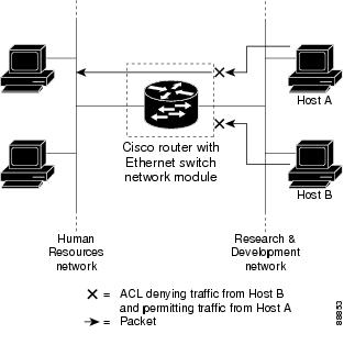
ACLs permit or deny packet forwarding based on how the packet matches the entries in the ACL. For example, you can use ACLs to allow one host to access a part of a network, but to prevent another host from accessing the same part. In Figure 17, ACLs applied at the switch input allow Host A to access the Human Resources network, but prevent Host B from accessing the same network.
Figure 17 Using ACLs to Control Traffic to a Network
Handling Fragmented and Unfragmented Traffic
IP packets can be fragmented as they cross the network. When this happens, only the fragment containing the beginning of the packet contains the Layer 4 information, such as TCP or UDP port numbers, ICMP type and code, and so on. All other fragments are missing this information.
Some ACEs do not check Layer 4 information and therefore can be applied to all packet fragments. ACEs that do test Layer 4 information cannot be applied in the standard manner to most of the fragments in a fragmented IP packet. When the fragment contains no Layer 4 information and the ACE tests some Layer 4 information, the matching rules are modified:
•
•
Consider access list 102, configured with these commands, applied to three fragmented packets:
Router(config)# access-list 102 permit tcp any host 10.1.1.1 eq smtpRouter(config)# access-list 102 deny tcp any host 10.1.1.2 eq telnetRouter(config)# access-list 102 deny tcp any any
Note
•
•
•
•
Understanding Access Control Parameters
Before configuring ACLs on the EtherSwitch Network Module, you must have a thorough understanding of the Access Control Parameters (ACPs). ACPs are referred to as masks in the switch CLI commands, and output.
Each ACE has a mask and a rule. The Classification Field or mask is the field of interest on which you want to perform an action. The specific values associated with a given mask are called rules.
Packets can be classified on these Layer 3 and Layer 4 fields.
•
–
–
You can use any combination or all of these fields simultaneously to define a flow.
•
–
–
Note
There are two types of masks:
•
•
Router(config-ext-nacl)# permit tcp any anyRouter(config-ext-nacl)# deny tcp any anyRouter(config-ext-nacl)# permit udp any anyRouter(config-ext-nacl)# deny udp any anyRouter(config-ext-nacl)# permit ip any anyRouter(config-ext-nacl)# deny ip any anyRouter(config-ext-nacl)# deny any anyRouter(config-ext-nacl)# permit any any
Note
The EtherSwitch Network Module ACL configuration is consistent with Cisco Catalyst switches. However, there are significant restrictions as well as differences for ACL configurations on the EtherSwitch Network Module.
Guidelines for Configuring ACLs on the EtherSwitch Network Module
These configuration guidelines apply to ACL filters:
•
•
The following example shows the same mask in an ACL:
Router(config)# ip access-list extended acl2Router(config-ext-nacl)# permit tcp 10.1.1.1 0.0.0.0 any eq 80Router(config-ext-nacl)# permit tcp 20.1.1.1 0.0.0.0 any eq 23In this example, the first ACE permits all the TCP packets coming from the host 10.1.1.1 with a destination TCP port number of 80. The second ACE permits all TCP packets coming from the host 20.1.1.1 with a destination TCP port number of 23. Both the ACEs use the same mask; therefore, a EtherSwitch Network Module supports this ACL.
•
Table 7 lists a summary of the ACL restrictions on EtherSwitch Network Modules.
Quality of Service for the EtherSwitch Network Module
Quality of service (QoS) can be implemented on your EtherSwitch Network Module. With this feature, you can provide preferential treatment to certain types of traffic. Without QoS, the switch offers best-effort service to each packet, regardless of the packet contents or size. It transmits the packets without any assurance of reliability, delay bounds, or throughput.
Understanding Quality of Service)
Typically, networks operate on a best-effort delivery basis, which means that all traffic has equal priority and an equal chance of being delivered in a timely manner. When congestion occurs, all traffic has an equal chance of being dropped.
With the QoS feature configured on your EtherSwitch Network Module, you can select specific network traffic, prioritize it according to its relative importance, and use congestion-management and congestion-avoidance techniques to provide preferential treatment. Implementing QoS in your network makes network performance more predictable and bandwidth utilization more effective.
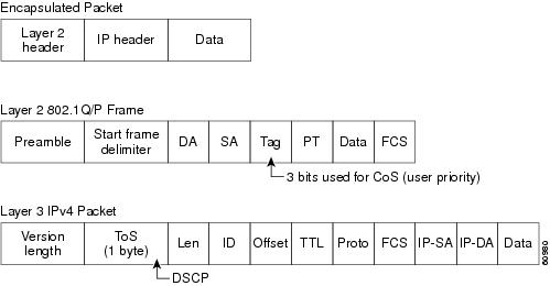
The QoS implementation for this release is based on the DiffServ architecture, an emerging standard from the Internet Engineering Task Force (IETF). This architecture specifies that each packet is classified upon entry into the network. The classification is carried in the IP packet header, using six bits from the deprecated IP type of service (ToS) field to carry the classification (class) information. Classification can also be carried in the Layer 2 frame. These special bits in the Layer 2 frame or a Layer 3 packet are described here and shown in Figure 18:
•
Layer 2 802.1Q frame headers have a 2-byte Tag Control Information field that carries the CoS value in the three most-significant bits, which are called the User Priority bits. On interfaces configured as Layer 2 802.1Q trunks, all traffic is in 802.1Q frames except for traffic in the native VLAN.
Other frame types cannot carry Layer 2 CoS values.
Layer 2 CoS values range from 0 for low priority to 7 for high priority.
•
Layer 3 IP packets can carry a Differentiated Services Code Point (DSCP) value. The supported DSCP values are 0, 8, 10, 16, 18, 24, 26, 32, 34, 40, 46, 48, and 56.
Figure 18 QoS Classification Layers in Frames and Packets
Note
Note
All switches and routers across the Internet rely on the class information to provide the same forwarding treatment to packets with the same class information and different treatment to packets with different class information. The class information in the packet can be assigned by end hosts or by switches or routers along the way, based on a configured policy, detailed examination of the packet, or both. Detailed examination of the packet is expected to happen closer to the edge of the network so that the core switches and routers are not overloaded.
Switches and routers along the path can use the class information to limit the amount of resources allocated per traffic class. The behavior of an individual device when handling traffic in the DiffServ architecture is called per-hop behavior. If all devices along a path provide a consistent per-hop behavior, you can construct an end-to-end QoS solution.
Implementing QoS in your network can be a simple or complex task and depends on the QoS features offered by your internetworking devices, the traffic types and patterns in your network, and the granularity of control you need over incoming and outgoing traffic.
The EtherSwitch Network Module can function as a Layer 2 switch connected to a Layer 3 router. When a packet enters the Layer 2 engine directly from a switch port, it is placed into one of four queues in the dynamic, 32-MB shared memory buffer. The queue assignment is based on the dot1p value in the packet. Any voice bearer packets that come in from the Cisco IP phones on the voice VLAN are automatically placed in the highest priority (Queue 3) based on the 802.1p value generated by the IP phone. The queues are then serviced on a weighted round robin (WRR) basis. The control traffic, which uses a CoS or ToS of 3, is placed in Queue 2.
Table 8 summarizes the queues, CoS values, and weights for Layer 2 QoS on the EtherSwitch Network Module.
Table 8 Queues, CoS Values, and Weights for Layer 2 QoS
3
5,6,7
255
2
3,4
64
1
2
16
0
0,1
1
The weights specify the number of packets that are serviced in the queue before moving on to the next queue. Voice Realtime Transport Protocol (RTP) bearer traffic marked with a CoS or ToS of 5 and Voice Control plane traffic marked with a CoS/ToS of 3 are placed into the highest priority queues. If the queue has no packets to be serviced, it is skipped. Weighted Random Early Detection (WRED) is not supported on the Fast Ethernet ports.
You cannot configure port-based QoS on the Layer 2 switch ports.
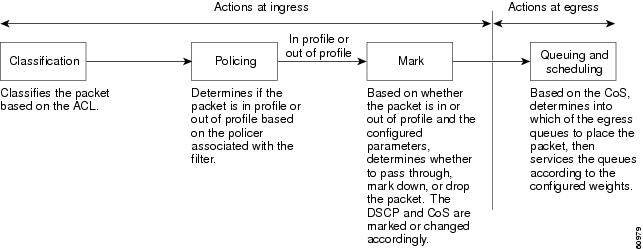
Basic QoS Model
Figure 19 shows the basic QoS model. Actions at the ingress interface include classifying traffic, policing, and marking:
•
•
•
Actions at the egress interface include queueing and scheduling:
•
•
Figure 19 Basic QoS Model
Classification
Classification is the process of distinguishing one kind of traffic from another by examining the fields in the packet.
Classification occurs only on a physical interface basis. No support exists for classifying packets at the VLAN or the switched virtual interface level.
You specify which fields in the frame or packet that you want to use to classify incoming traffic.
Classification Based on QoS ACLs
You can use IP standard or IP extended ACLs to define a group of packets with the same characteristics (class). In the QoS context, the permit and deny actions in the access control entries (ACEs) have different meanings than with security ACLs:
•
•
•
•
•
–
–
–
Note
•
After a traffic class has been defined with the ACL, you can attach a policy to it. A policy might contain multiple classes with actions specified for each one of them. A policy might include commands to rate-limit the class. This policy is then attached to a particular port on which it becomes effective.
You implement IP ACLs to classify IP traffic by using the access-list global configuration command.
Classification Based on Class Maps and Policy Maps
A class map is a mechanism that you use to isolate and name a specific traffic flow (or class) from all other traffic. The class map defines the criteria used to match against a specific traffic flow to further classify it; the criteria can include matching the access group defined by the ACL. If you have more than one type of traffic that you want to classify, you can create another class map and use a different name. After a packet is matched against the class-map criteria, you further classify it through the use of a policy map.
A policy map specifies which traffic class to act on. Actions can include setting a specific DSCP value in the traffic class or specifying the traffic bandwidth limitations and the action to take when the traffic is out of profile. Before a policy map can be effective, you must attach it to an interface.
The policy map can also contain commands that define the policer, the bandwidth limitations of the traffic, and the action to take if the limits are exceeded. For more information, see the "Policing and Marking" section.
A policy map also has these characteristics:
•
•
•
For configuration information, see the "Configuring a QoS Policy" section.
Policing and Marking
Policing involves creating a policer that specifies the bandwidth limits for the traffic. Packets that exceed the limits are out of profile or nonconforming. Each policer specifies the action to take for packets that are in or out of profile. These actions, carried out by the marker, include dropping the packet, or marking down the packet with a new value that is user-defined.
You can create this type of policer:
Individual—QoS applies the bandwidth limits specified in the policer separately to each matched traffic class. You configure this type of policer within a policy map by using the policy-map configuration command.
For non-IP traffic, you have these marking options:
•
•
The trust DSCP configuration is meaningless for non-IP traffic. If you configure a port with this option and non-IP traffic is received, the switch assigns the default port CoS value and classifies traffic based on the CoS value.
For IP traffic, you have these classification options:
•
•
When configuring policing and policers, keep these items in mind:
•
•
•
•
•
–
–
–
•
•
Note
Mapping Tables
The EtherSwitch Network Modules support these types of marking to apply to the switch:
•
•
Note
Before the traffic reaches the scheduling stage, QoS uses the configurable DSCP-to-CoS map to derive a CoS value from the internal DSCP value.
The CoS-to-DSCP and DSCP-to-CoS map have default values that might or might not be appropriate for your network.
How to Configure the EtherSwitch Network Module
This section contains the following tasks:
•
•
•
•
•
•
•
•
•
•
•
•
•
•
•
•
•
•
•
•
•
•
•
•
•
•
•
Configuring VLANs
Perform this task to configure the VLANs on an EtherSwitch Network Module.
VLAN Removal from the Database
You cannot delete the default VLANs for the different media types: Ethernet VLAN 1 and FDDI or Token Ring VLANs 1002 to 1005.
SUMMARY STEPS
1.
2.
3.
4.
5.
6.
DETAILED STEPS
Examples
Sample Output for the show vlan-switch Command
In the following example, output information is displayed to verify the VLAN configuration:
Router# show vlan-switch name vlan0003VLAN Name Status Ports---- -------------------------------- --------- -------------------------------1 default active Fa1/0, Fa1/1, Fa1/2, Fa1/3Fa1/4, Fa1/5, Fa1/6, Fa1/7Fa1/8, Fa1/9, Fa1/10, Fa1/11Fa1/12, Fa1/13, Fa1/14, Fa1/151002 fddi-default active1003 token-ring-default active1004 fddinet-default active1005 trnet-default activeVLAN Type SAID MTU Parent RingNo BridgeNo Stp BrdgMode Trans1 Trans2---- ----- ---------- ----- ------ ------ -------- ---- -------- ------ ------1 enet 100001 1500 - - - - - 1002 10031002 fddi 101002 1500 - - - - - 1 10031003 tr 101003 1500 1005 0 - - srb 1 10021004 fdnet 101004 1500 - - 1 ibm - 0 01005 trnet 101005 1500 - - 1 ibm - 0 0In the following example, the brief keyword is used to verify that VLAN 2 has been deleted:
Router# show vlan-switch briefVLAN Name Status Ports---- -------------------------------- --------- -------------------------------1 default active Fa0/2, Fa0/9, Fa0/14, Gi0/03 VLAN0003 active Fa0/4, Fa0/5, Fa0/10, Fa0/114 VLAN0004 active Fa0/6, Fa0/7, Fa0/12, Fa0/135 VLAN0005 active40 VLAN0040 active Fa0/1550 VLAN0050 active1000 VLAN1000 active1002 fddi-default active1003 token-ring-default active1004 fddinet-default active1005 trnet-default activeConfiguring VLAN Trunking Protocol
Perform this task to configure the VLAN Trunking Protocol (VTP) on an EtherSwitch Network Module.
VTP Mode Behavior
SUMMARY STEPS
1.
2.
3.
4.
5.
6.
7.
8.
9.
10.
DETAILED STEPS
Examples
Sample Output for the show vtp Command
In the following example, output information about the VTP management domain is displayed:
Router# show vtp statusVTP Version : 2Configuration Revision : 247Maximum VLANs supported locally : 1005Number of existing VLANs : 33VTP Operating Mode : ClientVTP Domain Name : Lab_NetworkVTP Pruning Mode : EnabledVTP V2 Mode : DisabledVTP Traps Generation : DisabledMD5 digest : 0x45 0x52 0xB6 0xFD 0x63 0xC8 0x49 0x80Configuration last modified by 0.0.0.0 at 8-12-99 15:04:49Configuring Spanning Tree on a VLAN
Perform this task to enable spanning tree on a per-VLAN basis and configure various spanning tree features. The EtherSwitch Network Module maintains a separate instance of spanning tree for each VLAN (except on VLANs on which you disable spanning tree).
VLAN Root Bridge
The EtherSwitch Network Module maintains a separate instance of spanning tree for each active VLAN configured on the device. A bridge ID, consisting of the bridge priority and the bridge MAC address, is associated with each instance. For each VLAN, the switch with the lowest bridge ID will become the root bridge for that VLAN.
To configure a VLAN instance to become the root bridge, the bridge priority can be modified from the default value (32768) to a significantly lower value so that the bridge becomes the root bridge for the specified VLAN. Use the spanning-tree vlan vlan-id root command to alter the bridge priority.
The switch checks the bridge priority of the current root bridges for each VLAN. The bridge priority for the specified VLANs is set to 8192 if this value will cause the switch to become the root for the specified VLANs.
If any root switch for the specified VLANs has a bridge priority lower than 8192, the switch sets the bridge priority for the specified VLANs to 1 less than the lowest bridge priority.
For example, if all switches in the network have the bridge priority for VLAN 100 set to the default value of 32768, entering the spanning-tree vlan 100 root primary command on a switch will set the bridge priority for VLAN 100 to 8192, causing the switch to become the root bridge for VLAN 100.
Note
Use the diameter keyword to specify the Layer 2 network diameter (that is, the maximum number of bridge hops between any two end stations in the Layer 2 network). When you specify the network diameter, the switch automatically picks an optimal hello time, forward delay time, and maximum age time for a network of that diameter, which can significantly reduce the spanning tree convergence time. You can use the hello-time keyword to override the automatically calculated hello time.
Note
VLAN Bridge Priority
Caution
SUMMARY STEPS
1.
2.
3.
4.
5.
6.
7.
8.
9.
10.
11.
12.
13.
DETAILED STEPS
Step 1
enable
Example:Router> enable
Enables privileged EXEC mode.
•
Step 2
configure terminal
Example:Router# configure terminal
Enters global configuration mode.
Step 3
spanning-tree vlan vlan-id [forward-time seconds | hello-time seconds | max-age seconds | priority priority | protocol protocol | [root {primary | secondary} [diameter net-diameter] [hello-time seconds]]]]
Example:Router(config)# spanning-tree vlan 200
Configures spanning tree on a per-VLAN basis.
•
•
Step 4
spanning-tree vlan vlan-id [priority priority]
Example:Router(config)# spanning-tree vlan 200 priority 33792
(Optional) Configures the bridge priority of a VLAN.
•
•
•
Step 5
spanning-tree vlan vlan-id [root {primary | secondary} [diameter net-diameter] [hello-time seconds]]
Example:Router(config)# spanning-tree vlan 200 root primary diameter 4
(Optional) Configures the EtherSwitch Network Module as the root bridge.
•
Step 6
spanning-tree vlan vlan-id [hello-time seconds]
Example:Router(config)# spanning-tree vlan 200 hello-time 7
(Optional) Configures the hello time of a VLAN.
•
•
Step 7
spanning-tree vlan vlan-id [forward-time seconds]
Example:Router(config)# spanning-tree vlan 200 forward-time 21
(Optional) Configures the spanning tree forward delay time of a VLAN.
•
•
Step 8
spanning-tree vlan vlan-id [max-age seconds]
Example:Router(config)# spanning-tree vlan 200 max-age 36
(Optional) Configures the maximum aging time of a VLAN.
•
•
Step 9
spanning-tree backbonefast
Example:Router(config)# spanning-tree vlan 200 max-age 36
(Optional) Enables BackboneFast on the EtherSwitch Network Module.
•
Note
Step 10
interface {ethernet | fastethernet | gigabitethernet} slot/port
Example:Router(config)# interface fastethernet 5/8
Selects the Ethernet interface to configure and enters interface configuration mode.
•
Step 11
spanning-tree port-priority port-priority
Example:Router(config-if)# spanning-tree port-priority 64
(Optional) Configures the port priority for an interface.
•
Step 12
spanning-tree cost cost
Example:Router(config-if)# spanning-tree cost 18
(Optional) Configures the port cost for an interface.
•
Step 13
exit
Example:Router(config-if)# exit
Exits interface configuration mode and returns the router to global configuration mode.
Verifying Spanning Tree on a VLAN
Perform this optional task to verify the spanning tree configuration on a VLAN.
SUMMARY STEPS
1.
2.
DETAILED STEPS
Step 1
Enables privileged EXEC mode. Enter your password if prompted:
Router> enableStep 2
Use this command with the vlan keyword to display spanning tree information about a specified VLAN:
Router# show spanning-tree vlan 200VLAN200 is executing the ieee compatible Spanning Tree protocolBridge Identifier has priority 32768, address 0050.3e8d.6401Configured hello time 2, max age 20, forward delay 15Current root has priority 16384, address 0060.704c.7000Root port is 264 (FastEthernet5/8), cost of root path is 38Topology change flag not set, detected flag not setNumber of topology changes 0 last change occurred 01:53:48 agoTimes: hold 1, topology change 24, notification 2hello 2, max age 14, forward delay 10Timers: hello 0, topology change 0, notification 0Port 264 (FastEthernet5/8) of VLAN200 is forwardingPort path cost 19, Port priority 128, Port Identifier 129.9.Designated root has priority 16384, address 0060.704c.7000Designated bridge has priority 32768, address 00e0.4fac.b000Designated port id is 128.2, designated path cost 19Timers: message age 3, forward delay 0, hold 0Number of transitions to forwarding state: 1BPDU: sent 3, received 3417Use this command with the interface keyword to display spanning tree information about a specified interface:
Router# show spanning-tree interface fastethernet 5/8Port 264 (FastEthernet5/8) of VLAN200 is forwardingPort path cost 19, Port priority 100, Port Identifier 129.8.Designated root has priority 32768, address 0010.0d40.34c7Designated bridge has priority 32768, address 0010.0d40.34c7Designated port id is 128.1, designated path cost 0Timers: message age 2, forward delay 0, hold 0Number of transitions to forwarding state: 1BPDU: sent 0, received 13513Use this command with the bridge, brief, and vlan keywords to display the bridge priority information:
Router# show spanning-tree bridge brief vlan 200Hello Max FwdVlan Bridge ID Time Age Delay Protocol---------------- -------------------- ---- ---- ----- --------VLAN200 33792 0050.3e8d.64c8 2 20 15 ieee
Configuring Layer 2 Interfaces
Perform this task to configure a range of interfaces, define a range macro, set the interface speed, set the duplex mode, and add a description for the interface.
Interface Speed and Duplex Mode Guidelines
When configuring an interface speed and duplex mode, note these guidelines:
•
•
•
Caution
SUMMARY STEPS
1.
2.
3.
4.
5.
6.
7.
8.
9.
10.
DETAILED STEPS
Examples
Sample Output for the show interfaces fastethernet Command
In the following example, output information is displayed to verify the speed and duplex mode of a Fast Ethernet interface:
Router# show interfaces fastethernet 1/4FastEthernet1/4 is up, line protocol is downHardware is Fast Ethernet, address is 0000.0000.0c89 (bia 0000.0000.0c89)MTU 1500 bytes, BW 100000 Kbit, DLY 100 usec,reliability 255/255, txload 1/255, rxload 1/255Encapsulation ARPA, loopback not setKeepalive set (10 sec)Auto-duplex, Auto-speedARP type: ARPA, ARP Timeout 04:00:00Last input never, output never, output hang neverLast clearing of "show interface" counters neverQueueing strategy: fifoOutput queue 0/40, 0 drops; input queue 0/75, 0 drops5 minute input rate 0 bits/sec, 0 packets/sec5 minute output rate 0 bits/sec, 0 packets/sec0 packets input, 0 bytes, 0 no bufferReceived 0 broadcasts, 0 runts, 0 giants, 0 throttles0 input errors, 0 CRC, 0 frame, 0 overrun, 0 ignored0 input packets with dribble condition detected3 packets output, 1074 bytes, 0 underruns(0/0/0)0 output errors, 0 collisions, 5 interface resets0 babbles, 0 late collision, 0 deferred0 lost carrier, 0 no carrier0 output buffer failures, 0 output buffers swapped outConfiguring an Ethernet Interface as a Layer 2 Trunk
Perform this task to configure an Ethernet interface as a Layer 2 trunk.
Restrictions
Note
SUMMARY STEPS
1.
2.
3.
4.
5.
6.
7.
8.
9.
10.
DETAILED STEPS
Examples
Sample Output for the show interfaces fastethernet Command
In the following two examples, output information is displayed to verify the configuration of Fast Ethernet interface as a Layer 2 trunk:
Router# show interfaces fastethernet 5/8 switchportName: Fa5/8Switchport: EnabledAdministrative Mode: static accessOperational Mode: static accessAdministrative Trunking Encapsulation: dot1qOperational Trunking Encapsulation: nativeNegotiation of Trunking: DisabledAccess Mode VLAN: 1 (default)Trunking Native Mode VLAN: 1 (default)Trunking VLANs Enabled: ALLPruning VLANs Enabled: 2-1001Protected: falseUnknown unicast blocked: falseUnknown multicast blocked: falseBroadcast Suppression Level: 100Multicast Suppression Level: 100Unicast Suppression Level: 100Voice VLAN: noneAppliance trust: noneRouter# show interfaces fastethernet 5/8 trunkPort Mode Encapsulation Status Native vlanFa1/15 off 802.1q not-trunking 1Port Vlans allowed on trunkFa1/15 1Port Vlans allowed and active in management domainFa1/15 1Port Vlans in spanning tree forwarding state and not prunedFa1/15 1Configuring an Ethernet Interface as a Layer 2 Access
Perform this task to configure an Ethernet interface as a Layer 2 access.
SUMMARY STEPS
1.
2.
3.
4.
5.
6.
7.
8.
DETAILED STEPS
Configuring Separate Voice and Data VLANs
Perform this task to configure separate voice and data VLANs on the EtherSwitch Network Module.
Separate Voice and Data VLANs
For ease of network administration and increased scalability, network managers can configure the EtherSwitch Network Module to support Cisco IP phones such that the voice and data traffic reside on separate VLANs. We recommend configuring separate VLANs when you are able to segment the existing IP address space of your branch office.
User priority bits in the 802.1p portion of the 802.1Q standard header are used to provide prioritization in Ethernet switches. This is a vital component in designing Cisco AVVID networks.
The EtherSwitch Network Module provides the performance and intelligent services of Cisco IOS software for branch office applications. The EtherSwitch Network Module can identify user applications—such as voice or multicast video—and classify traffic with the appropriate priority levels. QoS policies are enforced using Layer 2 and 3 information such as 802.1p, IP precedence, and DSCP.
Note
Voice Traffic and Voice VLAN ID (VVID) Using the EtherSwitch Network Module
The EtherSwitch Network Module can automatically configure voice VLAN. This capability overcomes the management complexity of overlaying a voice topology onto a data network while maintaining the quality of voice traffic. With the automatically configured voice VLAN feature, network administrators can segment phones into separate logical networks, even though the data and voice infrastructure is physically the same. The voice VLAN feature places the phones into their own VLANs without the need for end-user intervention. A user can plug the phone into the switch, and the switch provides the phone with the necessary VLAN information.
SUMMARY STEPS
1.
2.
3.
4.
5.
6.
DETAILED STEPS
Configuring a Single Voice and Data VLAN
Perform this task to configure a Cisco IP phone to send voice and data traffic on the same VLAN on the EtherSwitch Network Module.
Single Voice and Data VLAN
For network designs with incremental IP telephony deployment, network managers can configure the EtherSwitch Network Module so that the voice and data traffic coexist on the same subnet. This might be necessary when it is impractical either to allocate an additional IP subnet for IP phones or to divide the existing IP address space into an additional subnet at the remote branch, it might be necessary to use a single IP address space for branch offices. (This is one of the simpler ways to deploy IP telephony.) When this is the case, you must still prioritize voice above data at both Layer 2 and Layer 3.
Layer 3 classification is already handled because the phone sets the type of service (ToS) bits in all media streams to an IP Precedence value of 5. (With Cisco CallManager Release 3.0(5), this marking changed to a Differentiated Services Code Point ([DSCP]) value of EF.) However, to ensure that there is
Layer 2 classification for admission to the multiple queues in the branch office switches, the phone must also use the User Priority bits in the Layer 2 802.1p header to provide class of service (CoS) marking. Setting the bits to provide marking can be done by having the switch look for 802.1p headers on the native VLAN.This configuration approach must address two key considerations:
•
•
SUMMARY STEPS
1.
2.
3.
4.
5.
6.
DETAILED STEPS
Managing the EtherSwitch Network Module
Use this task to perform basic management tasks such as adding a trap manager and assigning IP information on the EtherSwitch Network Module with the Cisco IOS CLI. You might find this information useful when you configure the EtherSwitch Network Module for the previous scenarios.
Trap Managers
A trap manager is a management station that receives and processes traps. When you configure a trap manager, community strings for each member switch must be unique. If a member switch has an IP address assigned to it, the management station accesses the switch by using its assigned IP address.
By default, no trap manager is defined, and no traps are issued.
IP Addressing
The recommended configuration for using multiple cables to connect IP phones to the Cisco AVVID network is to use a separate IP subnet and separate VLANs for IP telephony.
IP Information Assigned to the Switch
You can use a BOOTP server to automatically assign IP information to the switch; however, the BOOTP server must be set up in advance with a database of physical MAC addresses and corresponding IP addresses, subnet masks, and default gateway addresses. In addition, the switch must be able to access the BOOTP server through one of its ports. At startup, a switch without an IP address requests the information from the BOOTP server; the requested information is saved in the switch running the configuration file. To ensure that the IP information is saved when the switch is restarted, save the configuration by entering the write memory command in privileged EXEC mode.
You can change the information in these fields. The mask identifies the bits that denote the network number in the IP address. When you use the mask to subnet a network, the mask is then referred to as a subnet mask. The broadcast address is reserved for sending messages to all hosts. The CPU sends traffic to an unknown IP address through the default gateway.
Use of Ethernet Ports to Support Cisco IP Phones with Multiple Ports
You might want to use multiple ports to connect the Cisco IP phones if any of the following conditions apply to your Cisco IP telephony network:
•
•
•
You want to limit the number of switches that need Uninterruptible Power Supply (UPS) power.
Domain Name Mapping and DNS Configuration
Each unique IP address can have a host name associated with it. IP defines a hierarchical naming scheme that allows a device to be identified by its location or domain. Domain names are pieced together with periods (.) as the delimiting characters. For example, Cisco Systems is a commercial organization that IP identifies by a com domain name, so its domain name is cisco.com. A specific device in this domain, the FTP system, for example, is identified as ftp.cisco.com.
To track domain names, IP has defined the concept of a domain name server (DNS), the purpose of which is to hold a cache (or database) of names mapped to IP addresses. To map domain names to IP addresses, you must first identify the host names and then specify a name server and enable the DNS, the Internet's global naming scheme that uniquely identifies network devices.
You can specify a default domain name that the software uses to complete domain name requests. You can specify either a single domain name or a list of domain names. When you specify a domain name, any IP host name without a domain name has that domain name appended to it before being added to the host table.
You can specify up to six hosts that can function as a name server to supply name information for the DNS.
If your network devices require connectivity with devices in networks for which you do not control name assignment, you can assign device names that uniquely identify your devices within the entire internetwork. The Internet's global naming scheme, the DNS, accomplishes this task. This service is enabled by default.
ARP Table Management
To communicate with a device (on Ethernet, for example), the software first must determine the 48-bit MAC or local data link address of that device. The process of determining the local data link address from an IP address is called address resolution.
The Address Resolution Protocol (ARP) associates a host IP address with the corresponding media or MAC addresses and VLAN ID. Taking an IP address as input, ARP determines the associated MAC address. Once a MAC address is determined, the IP-MAC address association is stored in an ARP cache for rapid retrieval. Then the IP datagram is encapsulated in a link-layer frame and sent over the network. Encapsulation of IP datagrams and ARP requests and replies on IEEE 802 networks other than Ethernet is specified by the Subnetwork Access Protocol (SNAP). By default, standard Ethernet-style ARP encapsulation (represented by the arpa keyword) is enabled on the IP interface.
When you manually add entries to the ARP Table by using the CLI, you must be aware that these entries do not age and must be manually removed.
SUMMARY STEPS
1.
2.
3.
4.
5.
6.
7.
8.
DETAILED STEPS
Configuring Voice Ports
Perform this task to instruct the Cisco 7960 IP phone to give voice traffic a higher priority and to forward all traffic through the 802.1Q native VLAN on the EtherSwitch Network Module. This task also disables inline power to a Cisco 7960 IP phone to allow voice traffic to be forwarded to and from the phone.
The EtherSwitch Network Module can connect to a Cisco 7960 IP phone and carry IP voice traffic. If necessary, the EtherSwitch Network Module can supply electrical power to the circuit connecting it to the Cisco 7960 IP phone.
Because the sound quality of an IP telephone call can deteriorate if the data is unevenly transmitted, the current release of the Cisco IOS software supports QoS based on IEEE 802.1p CoS. QoS uses classification and scheduling to transmit network traffic from the switch in a predictable manner.
The Cisco 7960 IP phone contains an integrated three-port 10/100 switch. The ports are dedicated to connect to the following devices:
•
•
•
Port Connection to a Cisco 7960 IP Phone
Because a Cisco 7960 IP phone also supports connection to a PC or other device, a port connecting a EtherSwitch Network Module to a Cisco 7960 IP phone can carry a mix of traffic. There are three ways to configure a port connected to a Cisco 7960 IP phone:
•
•
•
Inline Power on an EtherSwitch Network Module
The EtherSwitch Network Module can supply inline power to a Cisco 7960 IP phone, if necessary. The Cisco 7960 IP phone can also be connected to an AC power source and supply its own power to the voice circuit. When the Cisco 7960 IP phone is supplying its own power, an EtherSwitch Network Module can forward IP voice traffic to and from the phone.
A detection mechanism on the EtherSwitch Network Module determines whether it is connected to a Cisco 7960 IP phone. If the switch senses that there is no power on the circuit, the switch supplies the power. If there is power on the circuit, the switch does not supply it.
You can configure the switch to never supply power to the Cisco 7960 IP phone and to disable the detection mechanism.
SUMMARY STEPS
1.
2.
3.
4.
5.
6.
DETAILED STEPS
Verifying Cisco Discovery Protocol
Perform this optional task to verify that Cisco Discovery Protocol (CDP) is enabled globally, is enabled on an interface, and to display information about neighboring equipment. CDP is enabled by default. For more details on CDP commands, see the Cisco IOS Network Management Command Reference.
SUMMARY STEPS
1.
2.
3.
4.
DETAILED STEPS
Step 1
Enables privileged EXEC mode. Enter your password if prompted:
Router> enableStep 2
Use this command to verify that CDP is globally enabled:
Router# show cdpGlobal CDP information:Sending CDP packets every 120 secondsSending a holdtime value of 180 secondsSending CDPv2 advertisements is enabledStep 3
Use this command to verify the CDP configuration on an interface:
Router# show cdp interface fastethernet 5/1FastEthernet5/1 is up, line protocol is upEncapsulation ARPASending CDP packets every 120 secondsHoldtime is 180 secondsStep 4
Use this command to verify information about the neighboring equipment:
Router# show cdp neighborsCapability Codes: R - Router, T - Trans Bridge, B - Source Route BridgeS - Switch, H - Host, I - IGMP, r - RepeaterDevice ID Local Intrfce Holdtme Capability Platform Port IDJAB023807H1 Fas 5/3 127 T S WS-C2948 2/46JAB023807H1 Fas 5/2 127 T S WS-C2948 2/45JAB023807H1 Fas 5/1 127 T S WS-C2948 2/44JAB023807H1 Gig 1/2 122 T S WS-C2948 2/50JAB023807H1 Gig 1/1 122 T S WS-C2948 2/49JAB03130104 Fas 5/8 167 T S WS-C4003 2/47JAB03130104 Fas 5/9 152 T S WS-C4003 2/48
Configuring the MAC Table to Provide Port Security
Perform this task to enable the MAC address secure option, create a static or dynamic entry in the MAC address table, and configure the aging timer.
Port security is implemented by providing the user with the option to make a port secure by allowing only well-known MAC addresses to send in data traffic.
MAC Addresses and VLANs
The EtherSwitch Network Module uses the MAC address tables to forward traffic between ports. All MAC addresses in the address tables are associated with one or more ports. These MAC tables include the following types of addresses:
•
•
•
The address tables list the destination MAC address and the associated VLAN ID, module, and port number associated with the address.
All addresses are associated with a VLAN. An address can exist in more than one VLAN and have different destinations in each. Multicast addresses, for example, could be forwarded to port 1 in VLAN 1 and ports 9, 10, and 11 in VLAN 5.
Each VLAN maintains its own logical address table. A known address in one VLAN is unknown in another until it is learned or statically associated with a port in the other VLAN. An address can be secure in one VLAN and dynamic in another. Addresses that are statically entered in one VLAN must be static addresses in all other VLANs.
Address Aging Time
Dynamic addresses are source MAC addresses that the switch learns and then drops when they are not in use. Use the Aging Time field to define how long the switch retains unseen addresses in the table. This parameter applies to all VLANs.
Setting too short an aging time can cause addresses to be prematurely removed from the table. Then when the switch receives a packet for an unknown destination, it floods the packet to all ports in the same VLAN as the receiving port. This unnecessary flooding can impact performance. Setting too long an aging time can cause the address table to be filled with unused addresses; it can cause delays in establishing connectivity when a workstation is moved to a new port.
Caution
Secure Addresses
The secure address table contains secure MAC addresses and their associated ports and VLANs. A secure address is a manually entered unicast address that is forwarded to only one port per VLAN. If you enter an address that is already assigned to another port, the switch reassigns the secure address to the new port.
You can enter a secure port address even when the port does not yet belong to a VLAN. When the port is later assigned to a VLAN, packets destined for that address are forwarded to the port.
Static Addresses
A static address has the following characteristics:
•
•
•
Because all ports are associated with at least one VLAN, the switch acquires the VLAN ID for the address from the ports that you select on the forwarding map. A static address in one VLAN must be a static address in other VLANs. A packet with a static address that arrives on a VLAN where it has not been statically entered is flooded to all ports and not learned.
SUMMARY STEPS
1.
2.
3.
4.
5.
6.
7.
DETAILED STEPS
Examples
Sample Output for the show mac-address-table Command
In the following example, output information is displayed to verify the configuration of the secure port:
Router# show mac-address-table secureSecure Address Table:Destination Address Address Type VLAN Destination Port------------------- ------------ ---- --------------------0003.0003.0003 Secure 1 FastEthernet 2/8In the following example, information about static and dynamic addresses in the MAC address table is displayed:Router# show mac-address-tableDestination Address Address Type VLAN Destination Port------------------- ------------ ---- --------------------0001.6443.6440 Static 1 Vlan10004.c16d.9be1 Dynamic 1 FastEthernet2/130004.ddf0.0282 Dynamic 1 FastEthernet2/130006.0006.0006 Dynamic 1 FastEthernet2/13001b.001b.ad45 Dynamic 1 FastEthernet2/13In the following example, information about the MAC address aging timer is displayed:Router# show mac-address-table aging-timerMac address aging time 23Configuring 802.1x Authentication
Perform the following tasks to configure 802.1x port-based authentication on the EtherSwitch Network Module:
•
•
•
802.1x Authentication Guidelines for the EtherSwitch Network Module
These are the 802.1x authentication configuration guidelines:
•
•
–
–
Switch Port Analyzer (SPAN) destination port—You can enable 802.1x on a port that is a SPAN destination port; however, 802.1x is disabled until the port is removed as a SPAN destination. You can enable 802.1x on a SPAN source port.
Table 9 shows the default 802.1x configuration.
Enabling 802.1x Authentication
To enable 802.1x port-based authentication, you must enable AAA and specify the authentication method list. A method list describes the sequence and authentication methods to be queried to authenticate a user.
The software uses the first method listed to authenticate users; if that method fails to respond, the software selects the next authentication method in the method list. This process continues until there is successful communication with a listed authentication method or until all defined methods are exhausted. If authentication fails at any point in this cycle, the authentication process stops, and no other authentication methods are attempted.
You control the port authorization state by using the dot1x port-control interface configuration command and these keywords:
•
•
•
To disable AAA, use the no aaa new-model global configuration command. To disable 802.1x AAA authentication, use the no form of the aaa authentication dot1x global configuration command. To disable 802.1x, use the dot1x port-control command with the force-authorized keyword or the no form of the dot1x port-control interface configuration command.
SUMMARY STEPS
1.
2.
3.
4.
5.
6.
7.
DETAILED STEPS
Step 1
enable
Example:Router> enable
Enables privileged EXEC mode.
•
Step 2
configure terminal
Example:Router# configure terminal
Enters global configuration mode.
Step 3
aaa new-model
Example:Router (config)# aaa new-model
Enables AAA.
Step 4
aaa authentication dot1x default group radius
Example:Router (config)# aaa authentication dot1x default group radius
Creates an 802.1x authentication method list.
To create a default list that is used when a named list is not specified in the authentication command, use the default keyword followed by the methods that are to be used in default situations. The default method list is automatically applied to all interfaces.
Enter at least one of these keywords:
•
•
Step 5
interface type slot/port
Example:Router (config)# interface fastethernet 5/1
Enters interface configuration mode and specifies the interface to be enabled for 802.1x port-based authentication.
Step 6
dot1x port-control [auto | force-authorized | force-unauthorized]
Example:Router (config-if)# dot1x port-control auto
Enables 802.1x port-based authentication on the interface.
For feature interaction information with trunk, dynamic, dynamic-access, EtherChannel, secure, and SPAN ports, see the "802.1x Authentication Guidelines for the EtherSwitch Network Module" section.
Step 7
exit
Example:Router(config)# exit
Exits interface configuration mode and returns the router to privileged EXEC mode.
•
Configuring the Switch-to-RADIUS-Server Communication
Perform this task to configure RADIUS server parameters.
RADIUS Security Servers
RADIUS security servers are identified by their host name or IP address, host name and specific UDP port numbers, or IP address and specific UDP port numbers. The combination of the IP address and UDP port number creates a unique identifier, which enables RADIUS requests to be sent to multiple UDP ports on a server at the same IP address. If two different host entries on the same RADIUS server are configured for the same service—for example, authentication—the second host entry configured acts as the fail-over backup to the first one. The RADIUS host entries are tried in the order that they were configured.
SUMMARY STEPS
1.
2.
3.
4.
5.
DETAILED STEPS
Configuring 802.1x Parameters (Retransmissions and Timeouts)
Perform this task to configure various 802.1x retransmission and timeout parameters. Because all of these parameters have default values, configuring them is optional.
Note
SUMMARY STEPS
1.
2.
3.
4.
5.
6.
7.
8.
9.
10.
11.
12.
13.
14.
DETAILED STEPS
Step 1
Router> enable
Enables privileged EXEC mode.
•
Step 2
configure terminal
Example:Router# configure terminal
Enters global configuration mode.
Step 3
interface {ethernet | fastethernet | gigabitethernet} slot/port
Example:Router(config)# interface fastethernet 5/6
Specifies the interface to which multiple hosts are indirectly attached and enters interface configuration mode.
Step 4
dot1x port-control [auto | force-authorized | force-unauthorized]
Example:Router (config-if)# dot1x port-control auto
Enables 802.1x port-based authentication on the interface.
For feature interaction information with trunk, dynamic, dynamic-access, EtherChannel, secure, and SPAN ports, see the "802.1x Authentication Guidelines for the EtherSwitch Network Module" section.
Step 5
dot1x multiple-hosts
Example:Router (config-if)# dot1x multiple-hosts
Allows multiple hosts (clients) on an 802.1x-authorized port.
Note
Step 6
exit
Example:Router(config-if)# exit
Exits interface configuration mode and returns the router to global configuration mode.
Step 7
dot1x max-req number-of-retries
Example:Router (config)# dot1x max-req 3
Sets the number of times that the switch sends an EAP-request/identity frame to the client before restarting the authentication process.
•
Step 8
dot1x re-authentication
Example:Router (config)# dot1x reauthentication
Enables periodic reauthentication of the client, which is disabled by default.
•
Step 9
dot1x timeout re-authperiod value
Example:Router (config)# dot1x timeout re-authperiod 1800
Sets the number of seconds between reauthentication attempts.
•
Note
Step 10
dot1x timeout tx-period value
Example:Router (config)# dot1x timeout tx-period 60
Sets the number of seconds that the EtherSwitch Network Module waits for a response to an EAP-request/identity frame from the client before retransmitting the request.
•
Step 11
dot1x timeout quiet-period value
Example:Router (config)# dot1x timeout quiet-period 600
Sets the number of seconds that the EtherSwitch Network Module remains in a quiet state following a failed authentication exchange with the client.
•
Step 12
dot1x default
Example:Router (config)# dot1x default
Resets the configurable 802.1x parameters to the default values.
Step 13
exit
Example:Router(config)# exit
Exits global configuration mode and returns the router to privileged EXEC mode.
Step 14
show dot1x [statistics] [interface interface-type interface-number]
Example:Router# show dot1x statistics interface fastethernet 0/1
(Optional) Displays 802.1x statistics, administrative status, and operational status for the EtherSwitch Network Module or a specified interface.
Examples
Sample Output for the show dot1x Command
In the following example, statistics appear for all the physical ports for the specified interface:
Router# show dot1x statistics fastethernet 0/1FastEthernet0/1Rx: EAPOL EAPOL EAPOL EAPOL EAP EAP EAPStart Logoff Invalid Total Resp/Id Resp/Oth LenError0 0 0 21 0 0 0Last LastEAPOLVer EAPOLSrc1 0002.4b29.2a03Tx: EAPOL EAP EAPTotal Req/Id Req/Oth622 445 0In the following example, global 802.1x parameters and a summary are displayed:
Router# show dot1xGlobal 802.1X Parametersreauth-enabled noreauth-period 3600quiet-period 60tx-period 30supp-timeout 30server-timeout 30reauth-max 2max-req 2802.1X Port SummaryPort Name Status Mode AuthorizedGi0/1 disabled n/a n/aGi0/2 enabled Auto (negotiate) no802.1X Port Details802.1X is disabled on GigabitEthernet0/1802.1X is enabled on GigabitEthernet0/2Status UnauthorizedPort-control AutoSupplicant 0060.b0f8.fbfbMultiple Hosts DisallowedCurrent Identifier 2Authenticator State MachineState AUTHENTICATINGReauth Count 1Backend State MachineState RESPONSERequest Count 0Identifier (Server) 2Reauthentication State MachineState INITIALIZEConfiguring Power Management on the Interfaces
Perform this task to manage the powering of the Cisco IP phones.
SUMMARY STEPS
1.
2.
3.
4.
5.
6.
DETAILED STEPS
Examples
Sample Output for the show power inline Command
In the following example, output information is displayed to verify the power configuration on the ports:
Router# show power inlinePowerSupply SlotNum. Maximum Allocated Status----------- -------- ------- --------- ------EXT-PS 1 165.000 20.000 PS1 GOOD PS2 ABSENTInterface Config Phone Powered PowerAllocated--------- ------ ----- ------- --------------FastEthernet1/0 auto no off 0.000 WattsFastEthernet1/1 auto no off 0.000 WattsFastEthernet1/2 auto no off 0.000 WattsFastEthernet1/3 auto no off 0.000 WattsFastEthernet1/4 auto unknown off 0.000 WattsFastEthernet1/5 auto unknown off 0.000 WattsFastEthernet1/6 auto unknown off 0.000 WattsFastEthernet1/7 auto unknown off 0.000 WattsFastEthernet1/8 auto unknown off 0.000 WattsFastEthernet1/9 auto unknown off 0.000 WattsFastEthernet1/10 auto unknown off 0.000 WattsFastEthernet1/11 auto yes on 6.400 WattsFastEthernet1/12 auto yes on 6.400 WattsFastEthernet1/13 auto no off 0.000 WattsFastEthernet1/14 auto unknown off 0.000 WattsFastEthernet1/15 auto unknown off 0.000 WattsConfiguring Storm Control
This section consists of two tasks. The first task enables global storm control, and the second task configures storm control on a per-port basis.
•
•
Enabling Global Storm Control
Perform this task to enable a specified type of global storm control.
SUMMARY STEPS
1.
2.
3.
4.
5.
DETAILED STEPS
Examples
Sample Output for the show interface counters Command
In the following example, output information is displayed to verify the number of packets discarded for the specified storm control suppression:
Router# show interface counters broadcastPort BcastSuppDiscardsFa0/1 0Fa0/2 0Enabling Per-Port Storm Control
Perform this task to configure storm control on a specified interface.
SUMMARY STEPS
1.
2.
3.
4.
5.
6.
7.
DETAILED STEPS
Examples
Sample Output for the show storm-control Command
In the following example, output information is displayed to verify the number of packets discarded for the specified storm control suppression:
Router# show storm-control broadcastInterface Filter State Upper Lower Current--------- ------------- ------- ------- -------Fa0/1 <inactive> 100.00% 100.00% 0.00%Fa0/2 <inactive> 100.00% 100.00% 0.00%Fa0/3 <inactive> 100.00% 100.00% 0.00%Fa0/4 Forwarding 30.00% 20.00% 20.32%Configuring Layer 2 EtherChannels (Port-Channel Logical Interfaces)
Perform this task to configure Layer 2 Ethernet interfaces as a Layer 2 EtherChannel, configure EtherChannel load balancing, and remove an Ethernet interface from an EtherChannel.
To configure Layer 2 EtherChannels, configure the Ethernet interfaces with the channel-group command, which creates the port-channel logical interface. You do not have to create a port-channel interface before assigning a physical interface to a channel group. A port-channel interface is created automatically when the channel group gets its first physical interface, if it is not already created.
Restrictions
•
•
SUMMARY STEPS
1.
2.
3.
4.
5.
6.
7.
8.
9.
10.
11.
DETAILED STEPS
Examples
Sample Output for the show interfaces fastethernet Command
In the following example, output information is displayed to verify the configuration of Fast Ethernet interface as a Layer 2 EtherChannel:
Router# show interfaces fastethernet 5/6 etherchannelPort state = EC-Enbld Up In-Bndl Usr-ConfigChannel group = 2 Mode = Desirable Gcchange = 0Port-channel = Po2 GC = 0x00020001Port indx = 1 Load = 0x55Flags: S - Device is sending Slow hello. C - Device is in Consistent state.A - Device is in Auto mode. P - Device learns on physical port.Timers: H - Hello timer is running. Q - Quit timer is running.S - Switching timer is running. I - Interface timer is running.Local information:Hello Partner PAgP Learning GroupPort Flags State Timers Interval Count Priority Method IfindexFa5/6 SC U6/S7 30s 1 128 Any 56Partner's information:Partner Partner Partner Partner GroupPort Name Device ID Port Age Flags Cap.Fa5/6 JAB031301 0050.0f10.230c 2/47 18s SAC 2FAge of the port in the current state: 00h:10m:57sSample Output for the show etherchannel Command
In the following example, output information about port channels for EtherChannel group 2 is displayed:
Router# show etherchannel 2 port-channelPort-channels in the group:----------------------Port-channel: Po2------------Age of the Port-channel = 00h:23m:33sLogical slot/port = 10/2 Number of ports in agport = 2GC = 0x00020001 HotStandBy port = nullPort state = Port-channel Ag-InusePorts in the Port-channel:Index Load Port-------------------1 55 Fa5/60 AA Fa5/7Time since last port bundled: 00h:23m:33s Fa5/6Configuring Flow Control on Gigabit Ethernet Ports
Perform this task to configure flow control on a Gigabit Ethernet port.
SUMMARY STEPS
1.
2.
3.
DETAILED STEPS
Examples
Sample Output for the show port flowcontrol Command
In the following example, output information is displayed to verify the flow control configuration on Gigabit Ethernet ports:
Router# show interfaces fastethernet 5/6 etherchannelPort Send-Flowcontrol Receive-Flowcntl RxPause TxPauseAdmin Oper Admin Oper----- ---------------- ---------------- ------- ------5/1 off off on disagree 0 05/2 off off off off 0 05/3 desired on desired off 10 10Configuring Intrachassis Stacking
Perform this task to extend Layer 2 switching in the router by connecting the Gigabit Ethernet ports of the EtherSwitch Network Module.
SUMMARY STEPS
1.
2.
3.
4.
5.
DETAILED STEPS
Configuring Switched Port Analyzer (SPAN)
Perform this task to configure the source and destination for a SPAN session.
SUMMARY STEPS
1.
2.
3.
4.
5.
DETAILED STEPS
Configuring Layer 3 Interfaces
Perform this task to configure a Layer 3 interface on the EtherSwitch Network Module. A physical interface on the EtherSwitch Network Module is configured as a Layer 3 interface and an IP address is assigned to the interface.
Layer 3 Interface Support for the EtherSwitch Network Module
The EtherSwitch Network Module supports two types of Layer 3 interfaces for routing and bridging:
•
•
Note
All Layer 3 interfaces require an IP address to route traffic (a routed port cannot obtain an IP address from a DHCP server, but the router can act as a DHCP server and serve IP addresses through a routed port).
Routed ports support only CEF switching (IP fast switching is not supported).
Note
SUMMARY STEPS
1.
2.
3.
4.
5.
6.
7.
DETAILED STEPS
Enabling and Verifying IP Multicast Layer 3 Switching
Perform this task to enable IP multicast routing globally, enable IP Protocol Independent Multicast (PIM) on a Layer 3 interface, and verify the IP multicast Layer 3 switching information.
You must enable IP multicast routing globally before enabling IP multicast Layer 3 switching on Layer 3 interfaces. Enable PIM on Layer 3 interfaces before adding IP multicast Layer 3 switching functions on those interfaces.
For complete IP multicast command reference information and configuration details, refer to the following documents:
•
•
SUMMARY STEPS
1.
2.
3.
4.
5.
6.
7.
8.
DETAILED STEPS
Examples
Sample Output for the show ip pim Command
In the following example, output information is displayed to verify the IP multicast Layer 3 switching information for an IP PIM Layer 3 interface:
Router# show ip pim interface countState:* - Fast Switched, D - Distributed Fast SwitchedH - Hardware Switching EnabledAddress Interface FS Mpackets In/Out10.15.1.20 GigabitEthernet4/8 * H 952/423713077010.20.1.7 GigabitEthernet4/9 * H 1385673757/3410.25.1.7 GigabitEthernet4/10* H 0/3410.11.1.30 FastEthernet6/26 * H 0/010.37.1.1 FastEthernet6/37 * H 0/01.22.33.44 FastEthernet6/47 * H 514/68Sample Output for the show ip mroute Command
In the following example, output information is displayed for the IP multicast routing table:
Router# show ip mroute countIP Multicast Statistics56 routes using 28552 bytes of memory13 groups, 3.30 average sources per groupForwarding Counts:Pkt Count/Pkts per second/Avg Pkt Size/Kilobits per secondOther counts:Total/RPF failed/Other drops(OIF-null, rate-limit etc)Group:224.2.136.89, Source count:1, Group pkt count:29051Source:132.206.72.28/32, Forwarding:29051/-278/1186/0, Other:85724/8/56665
Note
Configuring IGMP Snooping
Perform this task to enable IGMP snooping on a router with the Ethernet switching network module installed.
IGMP Snooping on the EtherSwitch Network Module
By default, IGMP snooping is globally enabled on the EtherSwitch Network Module. When globally enabled or disabled, it is also enabled or disabled in all existing VLAN interfaces. By default, IGMP snooping is enabled on all VLANs, but it can be enabled and disabled on a per-VLAN basis.
Global IGMP snooping overrides the per-VLAN IGMP snooping capability. If global snooping is disabled, you cannot enable VLAN snooping. If global snooping is enabled, you can enable or disable snooping on a VLAN basis.
IGMP Immediate-Leave Processing
When you enable IGMP Immediate-Leave processing, the EtherSwitch Network Module immediately removes a port from the IP multicast group when it detects an IGMP version 2 leave message on that port. Immediate-Leave processing allows the switch to remove an interface that sends a leave message from the forwarding table without first sending out group-specific queries to the interface. You should use the Immediate-Leave feature only when there is only a single receiver present on every port in the VLAN.
Static Configuration of an Interface to Join a Multicast Group
Ports normally join multicast groups through the IGMP report message, but you can also statically configure a host on an interface.
SUMMARY STEPS
1.
2.
3.
4.
5.
6.
7.
8.
9.
10.
11.
DETAILED STEPS
Configuring Fallback Bridging
This section contains the following tasks to help you configure fallback bridging.
•
•
•
Understanding the Default Fallback Bridging Configuration
Table 10 shows the default fallback bridging configuration.
Configuring a Bridge Group
Perform this task to create a bridge group, filter frames using a specific MAC address, prevent the forwarding of frames for stations that the switching device has dynamically learned, and remove dynamic entries from the bridge table.
Bridge Group Creation
To configure fallback bridging for a set of SVIs or routed ports, these interfaces must be assigned to bridge groups. All interfaces in the same group belong to the same bridge domain. Each SVI or routed port can be assigned to only one bridge group. A maximum of 31 bridge groups can be configured on the switch.
Note
Forwarding of Dynamically Learned Stations
By default, the switch forwards any frames for stations that it has dynamically learned. By disabling this activity, the switch only forwards frames whose addresses have been statically configured into the forwarding cache.
Bridge Table Aging Time
A switch forwards, floods, or drops packets based on the bridge table. The bridge table maintains both static and dynamic entries. Static entries are entered by you or learned by the switch. Dynamic entries are entered by the bridge learning process. A dynamic entry is automatically removed after a specified length of time, known as aging time, from the time the entry was created or last updated.
If you are likely to move hosts on a switched network, decrease the aging-time to enable the switch to quickly adapt to the change. If hosts on a switched network do not continuously send packets, increase the aging time to keep the dynamic entries for a longer time and thus reduce the possibility of flooding when the hosts send again.
SUMMARY STEPS
1.
2.
3.
4.
5.
6.
7.
8.
9.
10.
DETAILED STEPS
Adjusting Spanning-Tree Parameters
Perform this task to adjust spanning tree parameters such as the switch priority or interface priority. You might need to adjust certain spanning-tree parameters if the default values are not suitable for your switch configuration. Parameters affecting the entire spanning tree are configured with variations of the bridge global configuration command. Interface-specific parameters are configured with variations of the bridge-group interface configuration command.
Note
Switch Priority
You can globally configure the priority of an individual switch when two switches tie for position as the root switch, or you can configure the likelihood that a switch will be selected as the root switch. This priority is determined by default; however, you can change it.
Interface Priority
You can change the priority for an interface. When two switches tie for position as the root switch, you configure an interface priority to break the tie. The switch with the lowest interface value is elected.
Path Cost Assignment
Each interface has a path cost associated with it. By convention, the path cost is 1000/data rate of the attached LAN, in Mbps.
BPDU Intervals Adjustment
You can adjust three different BPDU intervals. The interval between hello BPDUs can be set. The forward-delay interval is the amount of time spent listening for topology change information after an interface has been activated for switching and before forwarding actually begins. The maximum-idle interval specifies the amount of time the switch waits to hear BPDUs from the root switch. If a switch does not hear BPDUs from the root switch within the specified interval, it recomputes the spanning-tree topology.
Note
SUMMARY STEPS
1.
2.
3.
4.
5.
6.
DETAILED STEPS
Disabling the Spanning Tree on an Interface
Perform this task to disable spanning tree on an interface. When a loop-free path exists between any two switched subnetworks, you can prevent BPDUs generated in one switching subnetwork from impacting devices in the other switching subnetwork, yet still permit switching throughout the network as a whole. For example, when switched LAN subnetworks are separated by a WAN, BPDUs can be prevented from traveling across the WAN link.
SUMMARY STEPS
1.
2.
3.
4.
5.
DETAILED STEPS
Configuring Network Security with ACLs at Layer 2
This section contains the following tasks:
•
•
•
•
•
Configuring ACLs on Layer 2 interfaces is the same as configuring ACLs on Cisco routers. The process is briefly described here. For more detailed information on configuring router ACLs, refer to the "IP Access List Features Roadmap." For detailed information about ACL commands, see the Cisco IOS Security Command Reference. For a list of Cisco IOS features not supported on the EtherSwitch Network Module, see the following section.
Restrictions
The EtherSwitch Network Module does not support these Cisco IOS router ACL-related features:
•
•
•
•
•
•
•
•
•
•
Creating Standard and Extended IP ACLs
This section describes how to create switch IP ACLs. An ACL is a sequential collection of permit and deny conditions. The switch tests packets against the conditions in an access list one by one. The first match determines whether the switch accepts or rejects the packet. Because the switch stops testing conditions after the first match, the order of the conditions is critical. If no conditions match, the switch denies the packet.
An ACL must first be created by specifying an access list number or name and access conditions. The ACL can then be applied to interfaces or terminal lines.
The software supports these styles of ACLs or IP access lists:
•
•
ACL Numbers
The number you use to denote your ACL shows the type of access list that you are creating. Table 11 lists the access list number and corresponding type and shows whether or not they are supported by the switch. The EtherSwitch Network Module supports IP standard and IP extended access lists, numbers 1 to 199 and 1300 to 2699.
Note
Note
Including Comments About Entries in ACLs
You can use the remark command to include comments (remarks) about entries in any IP standard or extended ACL. The remarks make the ACL easier for you to understand and scan. Each remark line is limited to 100 characters.
The remark can go before or after a permit or deny statement. You should be consistent about where you put the remark so that it is clear which remark describes which permit or deny statement. For example, it would be confusing to have some remarks before the associated permit or deny statements and some remarks after the associated statements.
For IP numbered standard or extended ACLs, use the access-list access-list number remark remark global configuration command to include a comment about an access list. To remove the remark, use the no form of this command.
For an entry in a named IP ACL, use the remark access-list global configuration command. To remove the remark, use the no form of this command.
Configuring a Numbered Standard ACL
Perform this task to create a numbered standard ACL.
Note
SUMMARY STEPS
1.
2.
3.
4.
5.
DETAILED STEPS
Configuring a Numbered Extended ACL
Perform this task to create a numbered extended ACL.
Extended ACLs
Although standard ACLs use only source addresses for matching, you can use an xtended ACL source and destination addresses for matching operations and optional protocol type information for finer granularity of control. Some protocols also have specific parameters and keywords that apply to that protocol.
These IP protocols are supported (protocol keywords are in parentheses in bold): Internet Protocol (ip), Transmission Control Protocol (tcp), or User Datagram Protocol (udp).
Supported parameters can be grouped into these categories:
•
•
Table 12 lists the possible filtering parameters for ACEs for each protocol type.
Table 12 Filtering Parameter ACEs Supported by Different IP Protocols
IP ToS byte1
No
No
Differentiated Services Code Point (DSCP)
No
No
IP source address
Yes
Yes
IP destination address
Yes
Yes
Fragments
No
No
TCP or UDP
Yes
Yes
Source port operator
Yes
Yes
Source port
Yes
Yes
Destination port operator
Yes
Yes
Destination port
Yes
Yes
TCP flag
No
No
1 No support for type of service (TOS) minimize monetary cost bit.
Note
When creating ACEs in numbered extended access lists, remember that after you create the list, any additions are placed at the end of the list. You cannot reorder the list or selectively add or remove ACEs from a numbered list.
Use the no access-list access-list-number global configuration command to delete the entire access list. You cannot delete individual ACEs from numbered access lists.
After an ACL is created, any additions (possibly entered from the terminal) are placed at the end of the list. You can add ACEs to an ACL, but deleting any ACE deletes the entire ACL.
Note
SUMMARY STEPS
1.
2.
3.
4.
5.
DETAILED STEPS
What to Do Next
After creating an ACL, you must apply it to an interface, as described in the "Applying the ACL to an Interface" section.
Configuring a Named Standard ACL
Perform this task to create a named standard ACL.
Named Standard ACL Creation
You can identify IP ACLs with an alphanumeric string (a name) rather than a number. You can use named ACLs to configure more IP access lists on a switch than if you use numbered access lists. If you identify your access list with a name rather than a number, the mode and command syntax are slightly different. However, not all commands that use IP access lists accept a named ACL.
Note
Consider these guidelines and limitations before configuring named ACLs:
•
•
Note
SUMMARY STEPS
1.
2.
3.
4.
or
permit {source source-wildcard | host source | any}5.
6.
DETAILED STEPS
Configuring a Named Extended ACL
You can identify IP ACLs with an alphanumeric string (a name) rather than a number. You can use named ACLs to configure more IP access lists on a switch than if you use numbered access lists. If you identify your access list with a name rather than a number, the mode and command syntax are slightly different. However, not all commands that use IP access lists accept a named ACL.
Note
Consider these guidelines and limitations before configuring named ACLs:
•
•
Note
SUMMARY STEPS
1.
2.
3.
4.
or
permit {source source-wildcard | host source | any} [operator port] {destination destination-wildcard | host destination | any} [operator port]5.
6.
DETAILED STEPS
Step 1
enable
Example:Router> enable
Enables privileged EXEC mode.
•
Step 2
configure terminal
Example:Router# configure terminal
Enters global configuration mode.
Step 3
ip access-list extended {access-list-number | name}
Example:Router(config)# ip access-list extended marketing
Defines an extended IP access list using a name and enters access-list configuration mode.
•
Step 4
deny {source source-wildcard | host source | any} protocol {source source-wildcard | host source | any} [operator port] {destination destination-wildcard | host destination | any} [operator port]
or
permit {source source-wildcard | host source | any} protocol {source source-wildcard | host source | any} [operator port] {destination destination-wildcard | host destination | any} [operator port]
Example:Router(config-acl# deny tcp any any
or
Router(config-acl)# permit tcp 10.2.1.4 0.0.0.255 eq telnet
Specifies one or more conditions denied or permitted to determine if the packet is forwarded or dropped.
See the "Configuring a Numbered Extended ACL" section for definitions of protocols and other keywords.
•
•
Step 5
exit
Example:Router(config-acl)# exit
Exits access-list configuration mode and returns the router to global configuration mode.
•
Step 6
show access-lists [number | name]
Example:Router# show access-lists marketing
Displays access list configuration information.
Applying the ACL to an Interface
Perform this task to control access to a Layer 2 or Layer 3 interface. After you create an ACL, you can apply it to one or more interfaces. ACLs can be applied on inbound interfaces. This section describes how to accomplish this task for network interfaces. Note these guidelines:
•
•
Note
For inbound ACLs, after receiving a packet, the switch checks the packet against the ACL. If the ACL permits the packet, the switch continues to process the packet. If the ACL rejects the packet, the switch discards the packet.
When you apply an undefined ACL to an interface, the switch acts as if the ACL has not been applied to the interface and permits all packets. Remember this behavior if you use undefined ACLs for network security.
SUMMARY STEPS
1.
2.
3.
4.
5.
DETAILED STEPS
Configuring Quality of Service (QoS) on the EtherSwitch Network Module
This section consists of the following tasks that must be performed to configure QoS on your EtherSwitch Network Module:
•
Prerequisites
Before configuring QoS, you must have a thorough understanding of the following items:
•
•
•
•
Restrictions
•
•
•
•
•
•
For more information on guidelines for configuring ACLs, see the "Classification Based on QoS ACLs" section.
QoS on Switching Devices
Default Settings
•
•
•
•
•
•
Trust State on Ports and SVIs Within the QoS Domain
Packets entering a QoS domain are classified at the edge of the QoS domain. When the packets are classified at the edge, the switch port within the QoS domain can be configured to one of the trusted states because there is no need to classify the packets at every switch within the QoS domain. Figure 20 shows a sample network topology.
Figure 20 Port Trusted States within the QoS Domain
Configuring Classification Using Port Trust States
Perform this task to configure the port to trust the classification of the traffic that it receives, and then define the default CoS value of a port or to assign the default Cos to all incoming packets on the port.
Note
SUMMARY STEPS
1.
2.
3.
4.
5.
6.
7.
DETAILED STEPS
Examples
The following is sample output from the show mls qos interface fastethernet0/1 command:
Router# show mls qos interface fastethernet 0/1FastEthernet0/1trust state: trust cosCOS override: disdefault COS: 0Configuring a QoS Policy
This section contains the following tasks:
•
•
•
Configuring a QoS policy typically requires classifying traffic into classes, configuring policies applied to those traffic classes, and attaching policies to interfaces.
For background information, see the "Classification" section and the "Policing and Marking" section.
Classifying Traffic by Using ACLs
You can classify IP traffic by using IP standard or IP extended ACLs. To create an IP standard ACL for IP traffic, see the "Configuring a Numbered Standard ACL" section and to create an IP extended ACL for IP traffic see the "Configuring a Numbered Extended ACL" section.
Classifying Traffic Using Class Maps
Perform this task to create a class map and to define the match criteria for classifying traffic. You use the class-map global configuration command to isolate a specific traffic flow (or class) from all other traffic and to name it. The class map defines the criteria to use to match against a specific traffic flow to further classify it. Match statements can include criteria such as an ACL. The match criterion is defined with one match statement entered within the class-map configuration mode.
Note
SUMMARY STEPS
1.
2.
3.
or
access-list access-list-number {deny | permit | remark} protocol {source source-wildcard | host source | any} [operator-port] {destination destination-wildcard | host destination | any} [operator-port]4.
5.
6.
7.
DETAILED STEPS
Step 1
enable
Example:Router> enable
Enables privileged EXEC mode.
•
Step 2
configure terminal
Example:Router# configure terminal
Enters global configuration mode.
Step 3
access-list access-list-number {deny | permit | remark} {source source-wildcard | host source | any}
or
access-list access-list-number {deny | permit | remark} protocol {source source-wildcard | host source | any} [operator port] {destination destination-wildcard | host destination | any} [operator port]
Example:Router(config)# access-list 103 permit any any tcp eq 80
Creates an IP standard or extended ACL for IP traffic.
•
•
•
Step 4
class-map class-map-name
Example:Router(config)# class-map class1
Creates a class map, and enters class-map configuration mode.
•
•
Step 5
match access-group acl-index-or-name
Example:Router(config-cmap)# match access-group 103
Defines the match criteria to classify traffic.
•
•
•
Step 6
exit
Example:Router(config-cmap)# exit
Exits class map configuration mode and returns the router to global configuration mode.
•
Step 7
show class-map [class-map-name]
Example:Router# show class-map class1
(Optional) Displays class maps and their matching criteria.
Classifying, Policing, and Marking Traffic Using Policy Maps
Perform this task to create a policy map. A policy map specifies which traffic class to act on. Actions can include trusting the CoS or DSCP values in the traffic class; setting a specific DSCP value in the traffic class; and specifying the traffic bandwidth limitations for each matched traffic class (policer) and the action to take when the traffic is out of profile (marking).
A separate policy-map class can exist for each type of traffic received through an interface. You can attach only one policy map per interface in the input direction.
SUMMARY STEPS
1.
2.
3.
or
access-list access-list-number {deny | permit | remark} protocol {source source-wildcard | host source | any} [operator-port] {destination destination-wildcard | host destination | any} [operator-port]4.
5.
6.
7.
8.
9.
10.
11.
DETAILED STEPS
Step 1
enable
Example:Router> enable
Enables privileged EXEC mode.
•
Step 2
configure terminal
Example:Router# configure terminal
Enters global configuration mode.
Step 3
access-list access-list-number {deny | permit | remark} {source source-wildcard | host source | any}
or
access-list access-list-number {deny | permit | remark} protocol {source source-wildcard | host source | any} [operator port] {destination destination-wildcard | host destination | any} [operator port]
Example:Router(config)# access-list 1 permit 10.1.0.0 0.0.255.255
Creates an IP standard or extended ACL for IP traffic.
•
•
Note
Step 4
policy-map policy-map-name
Example:Router(config)# policy-map flow1t
Creates a policy map by entering the policy map name, and enters policy-map configuration mode.
•
•
Step 5
class {class-map-name | class-default} [access-group acl-index-or-name]
Example:Router(config-pmap)# class ipclass1
Defines a traffic classification, and enters policy-map class configuration mode.
•
•
•
•
Step 6
police {bps | cir bps} [burst-byte | bc burst-byte] conform-action transmit [exceed-action {drop | dscp dscp-value}]
Example:Router(config-pmap)# police 5000000 8192 conform-action transmit exceed-action dscp 10
Defines a policer for the classified traffic.
•
•
•
•
Step 7
exit
Example:Router(config-pmap)# exit
Exits policy map configuration mode and returns the router to global configuration mode.
Step 8
interface {ethernet | fastethernet | gigabitethernet} slot/port
Example:Router(config)# interface fastethernet 5/6
Enters interface configuration mode, and specifies the interface to attach to the policy map.
•
Step 9
service-policy input policy-map-name
Example:Router(config-if)# service-policy input flow1t
Applies a policy map to the input of a particular interface.
•
•
Step 10
exit
Example:Router(config-class-map)# exit
Exits class map configuration mode and returns the router to global configuration mode.
•
Step 11
show policy-map policy-map-name class class-map-name
Example:Router# show policy-map flow1t class class1
(Optional) Displays the configuration for the specified class of the specified policy map.
Configuring the CoS-to-DSCP Map
Perform this task to modify the CoS-to-DSCP map. You use the CoS-to-DSCP map to map CoS values in incoming packets to a DSCP value that QoS uses internally to represent the priority of the traffic.
Table 13 shows the default CoS-to-DSCP map.
If these values are not appropriate for your network, you need to modify them. These CoS-to-DSCP mapping numbers follow the numbers used in deploying Cisco AVVID and may be different from the mapping numbers used by the EtherSwitch Network Module, Cisco Catalyst 2950, Cisco Catalyst 3550, and other switches.
SUMMARY STEPS
1.
2.
3.
4.
5.
DETAILED STEPS
Configuring the DSCP-to-CoS Map
Perform this task to modify the DSCP-to-CoS map. You use the DSCP-to-CoS map to map DSCP values in incoming packets to a CoS value, which is used to select one of the four egress queues. The EtherSwitch Network Modules support these DSCP values: 0, 8, 10, 16, 18, 24, 26, 32, 34, 40, 46, 48, and 56.
Table 14 shows the default DSCP-to-CoS map.
Table 14 Default DSCP-to-CoS Map
DSCP values
0
8, 10
16, 18
24, 26
32, 34
40, 46
48
56
CoS values
0
1
2
3
4
5
6
7
If these values are not appropriate for your network, you need to modify them. These DSCP-to-CoS mapping numbers follow the numbers used in deploying Cisco AVVID and may be different from the mapping numbers used by the EtherSwitch Network Module, Cisco Catalyst 2950, Cisco Catalyst 3550, and other switches.
SUMMARY STEPS
1.
2.
3.
4.
5.
DETAILED STEPS
Configuration Examples for the EtherSwitch Network Module
This section contains the following configuration examples:
•
•
•
•
•
•
•
•
•
•
•
•
•
Configuring VLANs: Example
The following example shows how to configure a VLAN:
Router# vlan databaseRouter(vlan)# vlan 2 media ethernet name vlan1502VLAN 2 added:Name: VLAN1502Router(vlan)# exitAPPLY completed.Exiting....Configuring VTP: Example
The following example shows how to configure a VTP server, configure a VTP client, configure VTP version 2, and disable VTP mode on the router:
Router# vlan databaseRouter(vlan)# vtp serverSetting device to VTP SERVER mode.Router(vlan)# vtp domain Lab_NetworkSetting VTP domain name to Lab_NetworkRouter(vlan)# vtp password WATERSetting device VLAN database password to WATER.Router(vlan)# vtp clientSetting device to VTP CLIENT mode.Router(vlan)# vtp v2-modeV2 mode enabled.Router(vlan)# vtp transparentSetting device to VTP TRANSPARENT mode.Router(vlan)# exitAPPLY completed.Exiting....Configuring Spanning Tree: Examples
Router# configure terminalRouter(config)# spanning-tree vlan 200Router(config)# spanning-tree vlan 200 priority 33792Router(config)# spanning-tree vlan 200 hello-time 7Router(config)# spanning-tree vlan 200 forward-time 21Router(config)# spanning-tree vlan 200 max-age 36Router(config)# spanning-tree backbonefastRouter(config-if)# exitRouter(config)# interface fastethernet 5/8Router(config-if)# spanning-tree vlan 200 port-priority 64Router(config-if)# spanning-tree cost 18Router(config-if)# exitRouter(config)# exitThe following example shows how to verify the configuration of VLAN 200 on the interface when it is configured as a trunk port:
Router# show spanning-tree vlan 200Port 264 (FastEthernet5/8) of VLAN200 is forwardingPort path cost 19, Port priority 64, Port Identifier 129.8.Designated root has priority 32768, address 0010.0d40.34c7Designated bridge has priority 32768, address 0010.0d40.34c7Designated port id is 128.1, designated path cost 0Timers: message age 2, forward delay 0, hold 0Number of transitions to forwarding state: 1BPDU: sent 0, received 13513The following example shows how to verify the configuration of the interface when it is configured as an access port:
Router# show spanning-tree interface fastethernet 5/8Port 264 (FastEthernet5/8) of VLAN200 is forwardingPort path cost 18, Port priority 100, Port Identifier 129.8.Designated root has priority 32768, address 0010.0d40.34c7Designated bridge has priority 32768, address 0010.0d40.34c7Designated port id is 128.1, designated path cost 0Timers: message age 2, forward delay 0, hold 0Number of transitions to forwarding state: 1BPDU: sent 0, received 13513Router# configure terminalRouter(config)# spanning-tree vlan 150Router(config)# endRouter#
Note
The following example shows spanning tree being disabled on VLAN 200:
Router# configure terminalRouter(config)# no spanning-tree vlan 200Router(config)# endThe following example shows the switch device being configured as the root bridge for VLAN 10, with a network diameter of 4:
Router# configure terminalRouter(config)# spanning-tree vlan 10 root primary diameter 4Router(config)# exitConfiguring Layer 2 Interfaces: Examples
This section contains the following examples:
•
•
•
•
•
Single Range Configuration: Example
The following example shows all Fast Ethernet interfaces 5/1 to 5/5 being reenabled:
Router(config)# interface range fastethernet 5/1 - 5Router(config-if)# no shutdownRouter(config-if)#*Oct 6 08:24:35: %LINK-3-UPDOWN: Interface FastEthernet5/1, changed state to up*Oct 6 08:24:35: %LINK-3-UPDOWN: Interface FastEthernet5/2, changed state to up*Oct 6 08:24:35: %LINK-3-UPDOWN: Interface FastEthernet5/3, changed state to up*Oct 6 08:24:35: %LINK-3-UPDOWN: Interface FastEthernet5/4, changed state to up*Oct 6 08:24:35: %LINK-3-UPDOWN: Interface FastEthernet5/5, changed state to up*Oct 6 08:24:36: %LINEPROTO-5-UPDOWN: Line protocol on Interface FastEthernet5/5, changed state to up*Oct 6 08:24:36: %LINEPROTO-5-UPDOWN: Line protocol on Interface FastEthernet5/3, changed state to up*Oct 6 08:24:36: %LINEPROTO-5-UPDOWN: Line protocol on Interface FastEthernet5/4, changed state to upRouter(config-if)#Multiple Range Configuration: Example
The following example shows how to use a comma to add different interface type strings to the range to reenable all Fast Ethernet interfaces in the range 5/1 to 5/5 and both Gigabit Ethernet interfaces 1/1 and 1/2:
Router(config-if)# interface range fastethernet 5/1 - 5, gigabitethernet 1/1 - 2Router(config-if)# no shutdownRouter(config-if)#*Oct 6 08:29:28: %LINK-3-UPDOWN: Interface FastEthernet5/1, changed state to up*Oct 6 08:29:28: %LINK-3-UPDOWN: Interface FastEthernet5/2, changed state to up*Oct 6 08:29:28: %LINK-3-UPDOWN: Interface FastEthernet5/3, changed state to up*Oct 6 08:29:28: %LINK-3-UPDOWN: Interface FastEthernet5/4, changed state to up*Oct 6 08:29:28: %LINK-3-UPDOWN: Interface FastEthernet5/5, changed state to up*Oct 6 08:29:28: %LINK-3-UPDOWN: Interface GigabitEthernet1/1, changed state to up*Oct 6 08:29:28: %LINK-3-UPDOWN: Interface GigabitEthernet1/2, changed state to up*Oct 6 08:29:29: %LINEPROTO-5-UPDOWN: Line protocol on Interface FastEthernet5/5, changed state to up*Oct 6 08:29:29: %LINEPROTO-5-UPDOWN: Line protocol on Interface FastEthernet5/3, changed state to up*Oct 6 08:29:29: %LINEPROTO-5-UPDOWN: Line protocol on Interface FastEthernet5/4, changed state to upRouter(config-if)#Range Macro Definition: Example
The following example shows an interface-range macro named enet_list being defined to select Fast Ethernet interfaces 5/1 through 5/4:
Router(config)# define interface-range enet_list fastethernet 5/1 - 4Router(config)#Router(config)# interface range macro enet_listRouter(config-if)#Optional Interface Features: Example
The following example shows the interface speed being set to 100 Mbps on the Fast Ethernet interface 5/4, the interface duplex mode set to full, and a description being added for the interface:
Router(config)# interface fastethernet 5/4Router(config-if)# speed 100Router(config-if)# duplex fullRouter(config-if)# description Channel-group to "Marketing"Configuring an Ethernet Interface as a Layer 2 Trunk: Example
Router# configure terminalEnter configuration commands, one per line. End with CNTL/Z.Router(config)# interface fastethernet 5/8Router(config-if)# shutdownRouter(config-if)# switchport trunk encapsulation dot1qRouter(config-if)# switchport mode trunkRouter(config-if)# no shutdownRouter(config-if)# endRouter# exitConfiguring Voice and Data VLANs: Examples
This section contains the following examples:
•
•
•
Separate Voice and Data VLANs: Example
The following example shows separate VLANs being configured for voice and data on the EtherSwitch Network Module:
interface fastethernet5/1description DOT1Q port to IP Phoneswitchport native vlan 50switchport mode trunkswitchport voice vlan 150interface vlan 150description voice vlanip address 10.150.1.1 255.255.255.0ip helper-address 172.20.73.14 (See Note below)interface vlan 50description data vlanip address 10.50.1.1 255.255.255.0This configuration instructs the IP phone to generate a packet with an 802.1Q VLAN ID of 150 with an 802.1p value of 5 (default for voice bearer traffic).
Note
Cisco IOS supports a DHCP server function. If this function is used, the EtherSwitch Network Module serves as a local DHCP server and a helper address would not be required.
Inter-VLAN Routing: Example
Configuring inter-VLAN routing is identical to the configuration on an EtherSwitch Network Module with an MSFC. Configuring an interface for WAN routing is consistent with other Cisco IOS platforms.
The following example provides a sample configuration:
interface vlan 160description voice vlanip address 10.6.1.1 255.255.255.0interface vlan 60description data vlanip address 10.60.1.1 255.255.255.0interface serial1/0ip address 172.16.1.2 255.255.255.0
Note
Single Subnet Configuration: Example
The EtherSwitch Network Module supports the use of an 802.1p-only option when configuring the voice VLAN. Using this option allows the IP phone to tag VoIP packets with a CoS of 5 on the native VLAN, while all PC data traffic is sent untagged.
The following example shows a single subnet configuration for the EtherSwitch Network Module switch:
interface fastethernet 5/2description Port to IP Phone in single subnetswitchport access vlan 40switchport voice vlan dot1pspanning-tree portfastThe EtherSwitch Network Module instructs the IP phone to generate an 802.1Q frame with a null VLAN ID value but with an 802.1p value (default is COS of 5 for bearer traffic). The voice and data VLANs are both 40 in this example.
Ethernet Ports on IP Phones with Multiple Ports: Example
The following example illustrates the configuration on the IP phone:
interface fastethernet 2/2switchport voice vlan 5switchport mode trunkThe following example illustrates the configuration on the PC:
interface fastethernet 2/3switchport access vlan 10
Note
Configuring 802.1x Authentication: Examples
This section contains the following examples:
•
•
•
Enabling 802.1x Authentication: Example
The following example shows how to enable AAA and 802.1x on Fast Ethernet port 0/1:
Router# configure terminalRouter(config)# aaa new-modelRouter(config)# aaa authentication dot1x default group radiusRouter(config)# interface fastethernet0/1Router(config-if)# dot1x port-control autoRouter(config-if)# endConfiguring the Switch-to-RADIUS-Server Communication: Example
The following example shows how to specify the server with IP address 172.20.39.46 as the RADIUS server, to use port 1612 as the authorization port, and to set the encryption key to rad123, matching the key on the RADIUS server:
Router(config)# radius-server host 172.20.39.46 auth-port 1612 key rad123Configuring 802.1x Parameters: Example
The following example shows how to enable periodic reauthentication, set the number of seconds between reauthentication attempts to 4000, and set the quiet time to 30 seconds on the EtherSwitch Network Module. The number of seconds to wait for an EAP-request/identity frame before transmitting is set to 60 seconds and the number of times the switch device will send the EAP-request/identity frames before restarting the authentication process is set to 5. 802.1x is enabled on Fast Ethernet interface 0/1 and multiple hosts are permitted.
Router(config)# dot1x re-authenticationRouter(config)# dot1x timeout re-authperiod 4000Router(config)# dot1x timeout quiet-period 30Router(config)# dot1x timeout tx-period 60Router(config)# dot1x max-req 5Router(config)# interface fastethernet0/1Router(config-if)# dot1x port-control autoRouter(config-if)# dot1x multiple-hostsConfiguring Storm-Control: Example
The following example shows global multicast suppression being enabled at 70 percent on Gigabit Ethernet interface 1 and the configuration being verified:
Router# configure terminalRouter(config)# interface gigabitethernet0/2Router(config-if)# storm-control multicast level 70Router(config-if)# endRouter# show storm-controlName: Gi0/2Switchport: EnabledAdministrative Mode: dynamic desirableOperational Mode: downAdministrative Trunking Encapsulation: dot1qNegotiation of Trunking: OnAccess Mode VLAN: 1 (default)Trunking Native Mode VLAN: 1 (default)Trunking VLANs Enabled: ALLPruning VLANs Enabled: 2-1001Port Protected: OffUnknown Unicast Traffic: AllowedUnknown Multicast Traffic: Not AllowedBroadcast Suppression Level: 100Multicast Suppression Level: 70Unicast Suppression Level: 100Configuring Layer 2 EtherChannels: Example
•
•
Layer 2 EtherChannels: Example
Router# configure terminalRouter(config)# interface range fastethernet 5/6 - 7Router(config-if)# channel-group 2 mode onRouter(config-if)# exitRouter(config)# port-channel load-balance src-dst-ipRemoving an EtherChannel: Example
The following example shows port-channel 1 being removed:
Router# configure terminalRouter(config)# no interface port-channel 1Router(config)# end
Note
Configuring Flow Control on Gigabit Ethernet Ports: Example
The following examples show how to turn transmit and receive flow control on and how to verify the flow-control configuration.
Port 4/0 flow control send administration status is set to on (port will send flowcontrol to far end):
Router# configure terminalEnter configuration commands, one per line. End with CNTL/Z.Router(config)# interface gigabitethernet4/0Router(config-if)# flowcontrol send onRouter(config-if)# endPort 4/0 flow control receive administration status is set to on (port will require far end to send flowcontrol):
Router# configure terminalEnter configuration commands, one per line. End with CNTL/Z.Router(config)# interface gigabitethernet4/0Router(config-if)# flowcontrol receive onRouter(config-if)# endThe following example shows flow control configuration being verified:Router# show interface gigabitethernet4/0GigabitEthernet4/0 is up, line protocol is upHardware is Gigabit Ethernet, address is 0087.c08b.4824 (bia0087.c08b.4824)MTU 1500 bytes, BW 1000000 Kbit, DLY 10 usec,reliability 255/255, txload 1/255, rxload 1/255Encapsulation ARPA, loopback not setKeepalive set (10 sec)output flow-control is off, input flow-control is on0 pause input, 0 pause outputFull-duplex, 1000Mb/sARP type:ARPA, ARP Timeout 04:00:00Last input 00:00:01, output never, output hang neverLast clearing of "show interface" counters neverInput queue:0/75/0/0 (size/max/drops/flushes); Total output drops:0Queueing strategy:fifoOutput queue:0/40 (size/max)5 minute input rate 0 bits/sec, 0 packets/sec5 minute output rate 0 bits/sec, 1 packets/sec398301 packets input, 29528679 bytes, 0 no bufferReceived 0 broadcasts, 0 runts, 0 giants, 0 throttles0 input errors, 0 CRC, 0 frame, 0 overrun, 0 ignored0 input packets with dribble condition detected790904 packets output, 54653461 bytes, 0 underruns0 output errors, 0 collisions, 5 interface resets0 babbles, 0 late collision, 0 deferred0 lost carrier, 0 no carrier0 output buffer failures, 0 output buffers swapped outThe following example shows how to configure Gigabit Ethernet interface 0/10 as a routed port and to assign it an IP address:
Router# configure terminalEnter configuration commands, one per line. End with CNTL/Z.Router(config)# interface gigabitethernet0/10Router(config-if)# no switchportRouter(config-if)# ip address 10.1.2.3 255.255.0.0Router(config-if)# no shutdownRouter(config-if)# endThe following is sample output from the show interfaces privileged EXEC command for Gigabit Ethernet interface 0/2:
Router# show interfaces gigabitethernet0/2GigabitEthernet0/2 is up, line protocol is upHardware is Gigabit Ethernet, address is 0002.4b29.4400 (bia 0002.4b29.4400)Internet address is 192.168.135.21/24MTU 1500 bytes, BW 100000 Kbit, DLY 10 usec,reliability 255/255, txload 1/255, rxload 1/255Encapsulation ARPA, loopback not setKeepalive set (10 sec)Full-duplex, 100Mb/sinput flow-control is off, output flow-control is offARP type: ARPA, ARP Timeout 04:00:00Last input 00:00:02, output 00:00:08, output hang neverLast clearing of "show interface" counters neverQueueing strategy: fifoOutput queue 0/40, 0 drops; input queue 0/75, 0 drops5 minute input rate 0 bits/sec, 0 packets/sec5 minute output rate 0 bits/sec, 0 packets/sec89604 packets input, 8480109 bytes, 0 no bufferReceived 81848 broadcasts, 0 runts, 0 giants, 0 throttles0 input errors, 0 CRC, 0 frame, 0 overrun, 0 ignored0 input packets with dribble condition detected60665 packets output, 6029820 bytes, 0 underruns0 output errors, 0 collisions, 16 interface resets0 babbles, 0 late collision, 0 deferred0 lost carrier, 0 no carrier0 output buffer failures, 0 output buffers swapped outThe following is sample output from the show ip interface privileged EXEC command for Gigabit Ethernet interface 0/2:
Router# show ip interface gigabitethernet0/2GigabitEthernet0/2 is up, line protocol is upInternet address is 192.168.135.21/24Broadcast address is 255.255.255.255Address determined by setup commandMTU is 1500 bytesHelper address is not setDirected broadcast forwarding is disabledMulticast reserved groups joined: 224.0.0.5 224.0.0.6Outgoing access list is not setInbound access list is not setProxy ARP is enabledLocal Proxy ARP is disabledSecurity level is defaultSplit horizon is enabledICMP redirects are always sentICMP unreachables are always sentICMP mask replies are never sentIP fast switching is enabledIP fast switching on the same interface is disabledIP Flow switching is disabledIP CEF switching is enabledIP CEF Fast switching turbo vectorIP multicast fast switching is enabledIP multicast distributed fast switching is disabledIP route-cache flags are Fast, CEFRouter Discovery is disabledIP output packet accounting is disabledIP access violation accounting is disabledTCP/IP header compression is disabledRTP/IP header compression is disabledProbe proxy name replies are disabledPolicy routing is disabledNetwork address translation is disabledWCCP Redirect outbound is disabledWCCP Redirect exclude is disabledBGP Policy Mapping is disabledThe following is sample output from the show running-config privileged EXEC command for Gigabit Ethernet interface 0/2:
Router# show running-config interface gigabitethernet0/2Building configuration...Current configuration : 122 bytes!interface GigabitEthernet0/2no switchportip address 192.168.135.21 255.255.255.0speed 100mls qos trust dscpendIntrachassis Stacking: Example
The following example shows how to stack GE port 2/0 to GE port 3/0 to form an extended VLAN within one chassis:
Router# config terminalRouter(config)# interface Gigabit 2/0Router(config-if)# switchport stacking-link interface Gigabit3/0The following example shows interchassis stacking being verified between GE port 2/0 and GE port 3/0:GigabitEthernet2/0 is up, line protocol is downInternal Stacking Link Active : Gi2/0 is stacked with Gi3/0Hardware is Gigabit Ethernet, address is 001b.3f2b.2c24 (bia 001b.3f2b.2c24)MTU 1500 bytes, BW 1000000 Kbit, DLY 10 usec,reliability 255/255, txload 1/255, rxload 1/255Encapsulation ARPA, loopback not setKeepalive set (10 sec)Full-duplex mode, link type is force-up, media type is unknown 0output flow-control is off, input flow-control is offFull-duplex, 1000Mb/sARP type: ARPA, ARP Timeout 04:00:00Last input 1d22h, output never, output hang neverLast clearing of "show interface" counters 1d22hQueueing strategy: fifoOutput queue 0/40, 0 drops; input queue 0/75, 0 drops5 minute input rate 0 bits/sec, 0 packets/sec5 minute output rate 0 bits/sec, 0 packets/sec250707 packets input, 19562597 bytes, 0 no bufferReceived 7 broadcasts, 0 runts, 0 giants, 0 throttles0 input errors, 0 CRC, 0 frame, 0 overrun, 0 ignored0 watchdog, 0 multicast, 0 pause input0 input packets with dribble condition detected7469804 packets output, 582910831 bytes, 0 underruns(0/0/0)0 output errors, 0 collisions, 0 interface resets0 babbles, 0 late collision, 0 deferred0 lost carrier, 0 no carrier, 0 pause output0 output buffer failures, 0 output buffers swapped outConfiguring Switched Port Analyzer (SPAN): Example
The following example shows SPAN session 1 being configured to monitor bidirectional traffic from source interface Fast Ethernet 5/1. Fast Ethernet interface 5/48 is configured as the destination for SPAN session 1 and Fast Ethernet interface 5/2 is removed as a SPAN source for SPAN session 1.
Router(config)# monitor session 1 source interface fastethernet 5/1Router(config)# monitor session 1 destination interface fastethernet 5/48Router(config)# no monitor session 1 source interface fastethernet 5/2Configuring Layer 3 Interfaces: Example
The following example shows how to configure Gigabit Ethernet interface 0/10 as a routed port and to assign it an IP address:
Router# configure terminalEnter configuration commands, one per line. End with CNTL/Z.Router(config)# interface gigabitethernet0/10Router(config-if)# no switchportRouter(config-if)# ip address 10.1.2.3 255.255.0.0Router(config-if)# no shutdownRouter(config-if)# endThe following is sample output from the show interfaces privileged EXEC command for Gigabit Ethernet interface 0/2:
Router# show interfaces gigabitethernet0/2GigabitEthernet0/2 is up, line protocol is upHardware is Gigabit Ethernet, address is 0002.4b29.4400 (bia 0002.4b29.4400)Internet address is 192.168.135.21/24MTU 1500 bytes, BW 100000 Kbit, DLY 10 usec,reliability 255/255, txload 1/255, rxload 1/255Encapsulation ARPA, loopback not setKeepalive set (10 sec)Full-duplex, 100Mb/sinput flow-control is off, output flow-control is offARP type: ARPA, ARP Timeout 04:00:00Last input 00:00:02, output 00:00:08, output hang neverLast clearing of "show interface" counters neverQueueing strategy: fifoOutput queue 0/40, 0 drops; input queue 0/75, 0 drops5 minute input rate 0 bits/sec, 0 packets/sec5 minute output rate 0 bits/sec, 0 packets/sec89604 packets input, 8480109 bytes, 0 no bufferReceived 81848 broadcasts, 0 runts, 0 giants, 0 throttles0 input errors, 0 CRC, 0 frame, 0 overrun, 0 ignored0 input packets with dribble condition detected60665 packets output, 6029820 bytes, 0 underruns0 output errors, 0 collisions, 16 interface resets0 babbles, 0 late collision, 0 deferred0 lost carrier, 0 no carrier0 output buffer failures, 0 output buffers swapped outThe following is sample output from the show ip interface privileged EXEC command for Gigabit Ethernet interface 0/2:
Router# show ip interface gigabitethernet0/2GigabitEthernet0/2 is up, line protocol is upInternet address is 192.168.135.21/24Broadcast address is 255.255.255.255Address determined by setup commandMTU is 1500 bytesHelper address is not setDirected broadcast forwarding is disabledMulticast reserved groups joined: 224.0.0.5 224.0.0.6Outgoing access list is not setInbound access list is not setProxy ARP is enabledLocal Proxy ARP is disabledSecurity level is defaultSplit horizon is enabledICMP redirects are always sentICMP unreachables are always sentICMP mask replies are never sentIP fast switching is enabledIP fast switching on the same interface is disabledIP Flow switching is disabledIP CEF switching is enabledIP CEF Fast switching turbo vectorIP multicast fast switching is enabledIP multicast distributed fast switching is disabledIP route-cache flags are Fast, CEFRouter Discovery is disabledIP output packet accounting is disabledIP access violation accounting is disabledTCP/IP header compression is disabledRTP/IP header compression is disabledProbe proxy name replies are disabledPolicy routing is disabledNetwork address translation is disabledWCCP Redirect outbound is disabledWCCP Redirect exclude is disabledBGP Policy Mapping is disabledThe following is sample output from the show running-config privileged EXEC command for Gigabit Ethernet interface 0/2:
Router# show running-config interface gigabitethernet0/2Building configuration...Current configuration : 122 bytes!interface GigabitEthernet0/2no switchportip address 192.168.135.21 255.255.255.0speed 100mls qos trust dscpendIGMP Snooping: Example
Default IGMP Snooping Configuration
IGMP snooping is enabled by default on a VLAN or subnet basis. Multicast routing has to be enabled on the router first and then PIM (Multicast routing protocol) has to be enabled on the VLAN interface so that the EtherSwitch Network Module acknowledges the IGMP join and leave messages that are sent from the hosts connected to the EtherSwitch Network Module.
Router(config)# ip multicast-routingRouter(config-if)# interface VLAN1Router(config-if)# ip-address 192.168.10.1 255.255.255.0Router(config-if)# ip pim sparse-modeThe following example shows the output from configuring IGMP snooping:
Router# show mac-address-table multicast igmp-snoopingSlot # :3--------------MACADDR VLANID INTERFACES0100.5e00.0001 10100.5e00.0002 10100.5e00.000d 10100.5e00.0016 10100.5e05.0505 1 Fa3/120100.5e06.0606 1 Fa3/130100.5e7f.ffff 1 Fa3/130100.5e00.0001 20100.5e00.0002 20100.5e00.000d 20100.5e00.0016 20100.5e00.0128 20100.5e05.0505 2 Fa3/100100.5e06.0606 2 Fa3/11The following example shows output from the show running-config interface privileged EXEC command for VLAN 1:
Router# show running-config interface vlan 1Building configuration...Current configuration :82 bytes!interface Vlan1ip address 192.168.4.90 255.255.255.0ip pim sparse-modeendThe following example shows output from the show running-config interface privileged EXEC command for VLAN 2:
Router# show running-config interface vlan 2Building configuration...Current configuration :82 bytes!interface Vlan2ip address 192.168.5.90 255.255.255.0ip pim sparse-modeendThe following example shows output verifying multicasting support:
Router# show ip igmp groupIGMP Connected Group MembershipGroup Address Interface Uptime Expires Last Reporter239.255.255.255 Vlan1 01:06:40 00:02:20 192.168.41.101224.0.1.40 Vlan2 01:07:50 00:02:17 192.168.5.90224.5.5.5 Vlan1 01:06:37 00:02:25 192.168.41.100224.5.5.5 Vlan2 01:07:40 00:02:21 192.168.31.100224.6.6.6 Vlan1 01:06:36 00:02:22 192.168.41.101224.6.6.6 Vlan2 01:06:39 00:02:20 192.168.31.101The following example shows output from the multicast routing table:
Router# show ip mrouteIP Multicast Routing TableFlags:D - Dense, S - Sparse, B - Bidir Group, s - SSM Group, C -Connected,L - Local, P - Pruned, R - RP-bit set, F - Register flag,T - SPT-bit set, J - Join SPT, M - MSDP created entry,X - Proxy Join Timer Running, A - Candidate for MSDP Advertisement,U - URD, I - Received Source Specific Host ReportOutgoing interface flags:H - Hardware switchedTimers:Uptime/ExpiresInterface state:Interface, Next-Hop or VCD, State/Mode(*, 239.255.255.255), 01:06:43/00:02:17, RP 0.0.0.0, flags:DCIncoming interface:Null, RPF nbr 0.0.0.0Outgoing interface list:Vlan1, Forward/Sparse, 01:06:43/00:02:17(*, 224.0.1.40), 01:12:42/00:00:00, RP 0.0.0.0, flags:DCLIncoming interface:Null, RPF nbr 0.0.0.0Outgoing interface list:Vlan2, Forward/Sparse, 01:07:53/00:02:14(*, 224.5.5.5), 01:07:43/00:02:22, RP 0.0.0.0, flags:DCIncoming interface:Null, RPF nbr 0.0.0.0Outgoing interface list:Vlan1, Forward/Sparse, 01:06:40/00:02:22Vlan2, Forward/Sparse, 01:07:44/00:02:17(*, 224.6.6.6), 01:06:43/00:02:18, RP 0.0.0.0, flags:DCIncoming interface:Null, RPF nbr 0.0.0.0Outgoing interface list:Vlan1, Forward/Sparse, 01:06:40/00:02:18Vlan2, Forward/Sparse, 01:06:43/00:02:16Configuring Fallback Bridging: Examples
This section contains the following examples:
•
•
•
•
Creating a Bridge Group: Example
The following example shows how to create bridge group 10, specify the VLAN-bridge STP to run in the bridge group, and assign an interface to the bridge group. The switch device is prevented from forwarding frames for stations that it has dynamically learned in bridge group 10, and the bridge table aging time is set to 200 seconds. Frames with a MAC address of 0800.cb00.45e9 are forwarded through an interface in bridge group 1.
Router(config)# bridge 10 protocol vlan-bridgeRouter(config)# interface gigabitethernet0/1Router(config-if)# no switchportRouter(config-if)# bridge-group 10Router(config-if)# exitRouter(config)# no bridge 10 acquireRouter(config)# bridge 10 aging-time 200Router(config)# bridge 1 address 0800.cb00.45e9 forward gigabitethernet0/1Adjusting Spanning Tree Parameters: Example
The following example shows how to set the switch priority to 100 for bridge group 10, how to change the priority of an interface to 20 in bridge group 10, and how to change the path cost on an interface to 20 in bridge group 10. In bridge group 10 the hello interval is changed to 5 seconds, the forward-delay interval is changed to 10 seconds, and the maximum-idle interval to 30 seconds.
Router(config)# bridge 10 priority 100Router(config)# interface gigabitethernet0/1Router(config-if)# bridge-group 10 priority 20Router(config-if)# bridge-group 10 path-cost 20Router(config)# bridge 10 hello-time 5Router(config)# bridge 10 forward-time 10Router(config)# bridge 10 max-age 30Disabling the Spanning Tree on an Interface: Example
The following example shows how to disable spanning tree on an interface in bridge group 10:
Router(config)# interface gigabitethernet0/1Router(config-if)# bridge group 10 spanning-disabledFallback Bridging with DLSW: Example
The following example shows how to configure fallback bridging with DLSW on the EtherSwitch Network Module. Using the network in Figure 21 this example shows how to bridge VLANs over routers. Normally VLANs terminate at a router. Note that both PCs are on the same subnet although they are actually separated by two routers. The fallback bridging creates a virtual bridge between the two PCs.
Figure 21 Fallback Bridging with DLSW Network Example
The following are partial configurations for Router A and Router B:
Router A
no spanning-tree vlan 1no spanning-tree vlan 100!bridge irb!dlsw local-peer peer-id 192.168.65.1dlsw remote-peer 0 tcp 192.168.66.1dlsw bridge-group 1!interface FastEthernet1/8switchport access vlan 100no ip address!interface Vlan1ip address 192.168.65.1 255.255.255.0!interface Vlan100no ip addressbridge-group 1bridge-group 1 spanning-disabled!bridge 1 protocol ieeecall rsvp-syncRouter B
no spanning-tree vlan 1no spanning-tree vlan 100!bridge irb!dlsw local-peer peer-id 192.168.66.1dlsw remote-peer 0 tcp 192.168.65.1dlsw bridge-group 1!interface FastEthernet1/8switchport access vlan 100no ip addressinterface Vlan1ip address 192.168.65.2 255.255.255.0!interface Vlan100no ip addressbridge-group 1bridge-group 1 spanning-disabled!bridge 1 protocol ieeecall rsvp-syncConfiguring Network Security with ACLs at Layer 2: Examples
•
•
•
•
•
•
Creating Numbered Standard and Extended ACLs: Example
The following example shows how to create a standard ACL to deny access to IP host 172.16.198.102, permit access to any others, and display the results:
Switch (config)# access-list 2 deny host 172.16.198.102Switch (config)# access-list 2 permit anyRouter(config)# endRouter# show access-listsStandard IP access list 2deny 171.69.198.102permit anyThe following example shows that the switch accepts addresses on network 10.0.0.0 subnets and denies all packets coming from 10.1.0.0 subnets. The ACL is then applied to packets entering Gigabit Ethernet interface 0/1:
Router(config)# access-list 2 permit 10.0.0.0 0.255.255.255Router(config)# access-list 2 deny 10.1.0.0 0.255.255.255Router(config)# interface gigabitethernet0/1Router(config-if)# ip access-group 2 inThe following example shows how to create and display an extended access list to deny Telnet access from any host in network 172.16.198.0 to any host in network 172.16.52.0 and permit any others (the eq keyword after the destination address means to test for the TCP destination port number equaling Telnet):
Router(config)# access-list 102 deny tcp 172.16.198.0 0.0.0.255 172.16.52.0 0.0.0.255 eq
telnet
Router(config)# access-list 102 permit tcp any anyRouter(config)# endRouter# show access-listsExtended IP access list 102deny tcp 172.16.198.0 0.0.0.255 172.16.52.0 0.0.0.255 eq telnetpermit tcp any anyThe following example shows an extended ACL with a network connected to the Internet and any host on the network being able to form TCP Telnet and SMTP connections to any host on the Internet:
Router(config)# access-list 102 permit tcp any 172.16.0.0 0.0.255.255 eq 23Router(config)# access-list 102 permit tcp any 172.17.0.0 0.0.255.255 eq 25Router(config)# interface gigabitethernet0/1Router(config-if)# ip access-group 102 inSMTP uses TCP port 25 on one end of the connection and a random port number on the other end. The same port numbers are used throughout the life of the connection. Mail packets coming in from the Internet have a destination port of 25. Because the secure system behind the switch always accepts mail connections on port 25, the incoming services are controlled.
Creating Named Standard and Extended ACLs: Example
The following example shows how you can delete individual ACEs from a named ACL:
Router(config)# ip access-list extended border-listRouter(config-ext-nacl)# no permit ip host 10.1.1.3 anyThe following example shows the marketing_group ACL allowing any TCP Telnet traffic to the destination address and wildcard 172.16.0.0 0.0.255.255 and denying any other TCP traffic. It permits any other IP traffic:
Router(config)# ip access-list extended marketing_groupRouter(config-ext-nacl)# permit tcp any 172.16.0.0 0.0.255.255 eq telnetRouter(config-ext-nacl)# deny tcp any anyRouter(config-ext-nacl)# permit ip any anyThe ACLs are applied to permit Gigabit Ethernet port 0/1, which is configured as a Layer 2 port, with the marketing_group ACL applied to incoming traffic.
Router(config)# interface gigabitethernet0/1Router(config-if)# ip access-group marketing_group inIncluding Comments About Entries in ACLs: Example
The following example shows an IP numbered standard ACL using the access-list access-list number remark remark global configuration command to include a comment about an access list. In this example, the workstation belonging to Jones is allowed access, and the workstation belonging to Smith is not allowed access:
Router(config)# access-list 1 remark Permit only Jones workstation throughRouter(config)# access-list 1 permit 172.16.2.88Router(config)# access-list 1 remark Do not allow Smith workstation throughRouter(config)# access-list 1 deny 172.17.3.13The following example shows an entry in a named IP ACL using the remark access-list global configuration command to include a comment about an access list. In this example, the Jones subnet is not allowed to use outbound Telnet:
Router(config)# ip access-list extended telnettingRouter(config-ext-nacl)# remark Do not allow Jones subnet to telnet outRouter(config-ext-nacl)# deny tcp host 172.16.2.88 any eq telnetIn this example of a numbered ACL, the workstation belonging to Jones is allowed access, and the workstation belonging to Smith is not allowed access:
Router(config)# access-list 1 remark Permit only Jones workstation throughRouter(config)# access-list 1 permit 172.16.2.88Router(config)# access-list 1 remark Do not allow Smith workstation throughRouter(config)# access-list 1 deny 172.16.3.13In this example of a numbered ACL, the Winter and Smith workstations are not allowed to browse the web:
Router(config)# access-list 100 remark Do not allow Winter to browse the webRouter(config)# access-list 100 deny host 172.16.3.85 any eq wwwRouter(config)# access-list 100 remark Do not allow Smith to browse the webRouter(config)# access-list 100 deny host 172.16.3.13 any eq wwwApplying the ACL to an Interface: Example
The following example shows how to apply access list 2 on Gigabit Ethernet interface 0/3 to filter packets entering the interface:
Router(config)# interface gigabitethernet0/3Router(config-if)# ip access-group 2 inDisplaying Standard and Extended ACLs: Example
The following example displays all standard and extended ACLs:
Router# show access-listsStandard IP access list 1permit 172.20.10.10Standard IP ACL 10permit 10.12.12.12Standard IP access list 12deny 10.3.3.2Standard IP access list 32permit 172.20.20.20Standard IP access list 34permit 10.24.35.56permit 10.45.56.34Extended IP access list 120The following example displays only IP standard and extended ACLs:
Router# show ip access-listsStandard IP access list 1permit 172.16.10.10Standard IP access list 10permit 10.12.12.12Standard IP access list 12deny 10.3.3.2Standard IP access list 32permit 172.20.20.20Standard IP access list 34permit 10.24.35.56permit 10.45.56.34Extended IP access list 120Displaying Access Groups: Example
You use the ip access-group interface configuration command to apply ACLs to a Layer 3 interface. When IP is enabled on an interface, you can use the show ip interface interface-id privileged EXEC command to view the input and output access lists on the interface, as well as other interface characteristics. If IP is not enabled on the interface, the access lists are not shown.
The following example shows how to view all access groups configured for VLAN 1 and for Gigabit Ethernet interface 0/2:
Router# show ip interface vlan 1GigabitEthernet0/2 is up, line protocol is downInternet address is 10.20.30.1/16Broadcast address is 255.255.255.255Address determined by setup commandMTU is 1500 bytesHelper address is not setDirected broadcast forwarding is disabledOutgoing access list is permit AnyInbound access list is 13...Router# show ip interface fastethernet 0/9FastEthernet0/9 is down, line protocol is downInbound access list is ip1The only way to ensure that you can view all configured access groups under all circumstances is to use the show running-config privileged EXEC command. To display the ACL configuration of a single interface, use the show running-config interface interface-id command.
The following example shows how to display the ACL configuration of Gigabit Ethernet interface 0/1:
Router# show running-config interface gigabitethernet0/1Building configuration...Current configuration :112 bytes!interface GigabitEthernet0/1ip access-group 11 insnmp trap link-statusno cdp enableendCompiling ACLs: Example
For more information about ACLs, see the "IP Access List Features Roadmap" module.
Figure 22 shows a small networked office with a stack of Catalyst 2950 switches that are connected to a Cisco router with an EtherSwitch Network Module installed. A host is connected to the network through the Internet using a WAN link.
Use switch ACLs to do these tasks:
•
•
Figure 22 Using Switch ACLs to Control Traffic
The following example uses a standard ACL to allow access to a specific Internet host with the address 172.16.128.64:
Router(config)# access-list 6 permit 172.16.128.64 0.0.0.0Router(config)# endRouter(config)# interface gigabitethernet0/1Router(config-if)# ip access-group 6 inThe following example uses an extended ACL to deny traffic from port 80 (HTTP). It permits all other types of traffic:
Router(config)# access-list 106 deny tcp any any eq 80Router(config)# access-list 106 permit ip any anyRouter(config)# interface gigabitethernet0/2Router(config-if)# ip access-group 106 inConfiguring QoS on the EtherSwitch Network Module: Examples
•
•
•
•
•
•
Classifying Traffic by Using ACLs: Example
The following example shows how to allow access for only those hosts on the two specified networks. The wildcard bits apply to the host portions of the network addresses. Any host with a source address that does not match the ACL statements is rejected.
Router(config)# access-list 1 permit 192.168.255.0 0.0.0.255Router(config)# access-list 1 permit 10.0.0.0 0.0.0.255Classifying Traffic by Using Class Maps: Example
The following example shows how to configure the class map called class1. The class1 has one match criterion, which is an ACL called 103.
Router(config)# access-list 103 permit any any tcp eq 80Router(config)# class-map class1Router(config-cmap)# match access-group 103Router(config-cmap)# endRouter#Classifying, Policing, and Marking Traffic by Using Policy Maps: Example
The following example shows how to create a policy map and attach it to an ingress interface. In the configuration, the IP standard ACL permits traffic from network 10.1.0.0. For traffic matching this classification, the DSCP value in the incoming packet is trusted. If the matched traffic exceeds an average traffic rate of 48000 bps and a normal burst size of 8000 bytes, its DSCP is marked down to a value of 10 and transmitted.
Router(config)# access-list 1 permit 10.1.0.0 0.0.255.255Router(config)# class-map ipclass1Router(config-cmap)# match access-group 1Router(config-cmap)# exitRouter(config)# policy-map flow1tRouter(config-pmap)# class ipclass1Router(config-pmap-c)# police 5000000 8192 exceed-action dscp 10Router(config-pmap-c)# exitRouter(config-pmap)# exitRouter(config)# interface gigabitethernet0/1Router(config-if)# switchport mode accessRouter(config-if)# service-policy input flow1tConfiguring the CoS-to-DSCP Map: Example
The following example shows how to modify and display the CoS-to-DSCP map:
Router# configure terminalRouter(config)# mls qos map cos-dscp 8 8 8 8 24 32 56 56Router(config)# endRouter# show mls qos maps cos-dscpCos-dscp map:cos: 0 1 2 3 4 5 6 7--------------------------------dscp: 8 8 8 8 24 32 56 56Configuring the DSCP-to-CoS Map: Example
The following example shows how the DSCP values 26 and 48 are mapped to CoS value 7. For the remaining DSCP values, the DSCP-to-CoS mapping is the default.
Router(config)# mls qos map dscp-cos 26 48 to 7Router(config)# exitRouter# show mls qos maps dscp-cosDscp-cos map:dscp: 0 8 10 16 18 24 26 32 34 40 46 48 56-----------------------------------------------cos: 0 1 1 2 2 3 7 4 4 5 5 7 7Displaying QoS Information: Example
The following example shows how to display the DSCP-to-CoS maps:
Router# show mls qos maps dscp-cosDscp-cos map:dscp: 0 8 10 16 18 24 26 32 34 40 46 48 56-----------------------------------------------cos: 0 1 1 2 2 3 3 4 4 5 5 6 7Additional References
The following sections provide references related to the EtherSwitch Network Module.
Related Documents
IP LAN switching commands: complete command syntax, command mode, defaults, usage guidelines, and examples
CDP commands
Quick Start Guide for the Cisco 2600 series
Hardware installation for the Cisco 2600 series
Quick Start Guide for the Cisco 3600 series
Hardware installation for the Cisco 3600 series
Quick Start Guide for the Cisco 3700 series
Hardware installation for the Cisco 3700 series
Information about Voice features
Voice over IP commands
Information about Flow Control
Information about implementing end-to-end QoS as you deploy Cisco AVVID solutions
Information on IP routing
"Configuring IP Routing Protocol-Independent Features" module in the Cisco IOS IP Routing: Protocol-Independent Configuration Guide.
Information about IP multicast configurations
"IP Multicast Features Roadmap" in the Cisco IOS IP Multicast Configuration Guide
IP multicast commands
Information about configuring router ACLs
"IP Access List Features Roadmap" module
ACL commands
Standards
MIBs
RFCs
Technical Assistance
Feature Information for EtherSwitch Network Module
Table 15 lists the release history for this feature.
Not all commands may be available in your Cisco IOS software release. For release information about a specific command, see the command reference documentation.
Use Cisco Feature Navigator to find information about platform support and software image support. Cisco Feature Navigator enables you to determine which Cisco IOS and Catalyst OS software images support a specific software release, feature set, or platform. To access Cisco Feature Navigator, go to http://www.cisco.com/go/cfn. An account on Cisco.com is not required.
Note
Table 15 Feature Information for EtherSwitch Network Module
EtherSwitch Network Module
12.2(2)XT
12.2(8)T
12.2(15)ZJ
12.3(4)TThe EtherSwitch Network Module is a modular, high-density voice network module that provides Layer 2 switching across Ethernet ports.
In 12.2(2)XT, this feature was introduced on the Cisco 2600 series, Cisco 3600 series, and Cisco 3700 series routers.
In 12.2(8)T, this feature was integrated into Cisco IOS Release 12.2(8)T.
In 12.2(15)ZJ, the following switching software enhancements were added: IEEE 802.1x, QoS (including Layer 2/Layer 3 CoS/DSCP mapping and rate limiting), security ACL, IGMP snooping, per-port storm control, and fallback bridging support for switch virtual interfaces (SVIs).
In 12.3(4)T, the switching software enhancements from Cisco IOS Release 12.2(15)ZJ were integrated into Cisco IOS Release 12.3(4)T.
The following sections provide information about this feature:
•
•
The following commands were introduced or modified: aaa authentication dot1x, class (EtherSwitch), debug dot1x (EtherSwitch), debug eswilp, debug ip igmp snooping, debug spanning-tree, dot1x default, dot1x max-req, dot1x multiple-hosts, dot1x port-control, dot1x re-authenticate (EtherSwitch), dot1x re-authentication, dot1x timeout (EtherSwitch), ip igmp snooping, ip igmp snooping vlan, ip igmp snooping vlan immediate-leave, ip igmp snooping vlan mrouter, ip igmp snooping vlan static, mls qos cos, mls qos map, mls qos trust, police (EtherSwitch), show dot1x (EtherSwitch), show ip igmp snoopin, show ip igmp snooping mrouter, show mls masks, show mls qos interface, show mls qos maps, show spanning-tree, show storm-control, spanning-tree backbonefast, storm-control, switchport.
Glossary
802.1d—IEEE standard for MAC bridges.
802.1p—IEEE standard for queuing and multicast support.
802.1q—IEEE standard for VLAN frame tagging.
802.1x—IEEE standard for port-based network access control.
ACE—access control entry. Entry in an access control list.
ACL—access control list. Used for security or as a general means to classify traffic.
AgPort—aggregate port (another name for EtherChannel).
ATM—Asynchronous Transfer Mode. The international standard for cell relay in which multiple service types (such as voice, video, or data) are conveyed in fixed-length (53-byte) cells. Fixed-length cells allow cell processing to occur in hardware, thereby reducing transit delays. ATM is designed to take advantage of high-speed transmission media such as E3, SONET, and T3.
authentication server—Entity that validates the credentials of a host trying to obtain access to the network.
authenticator—Entity that enforces authentication rules for hosts connecting to a LAN via one of its ports.
authorization state—The state of a controlled port. It can be authorized (access allowed) or unauthorized (access denied).
AVVID—Architecture for voice, video, and integrated data.
BRI—Basic Rate Interface. ISDN interface comprising two B channels and one D channel for circuit-switched communication of voice, video, and data.
CAC—connection admission control. Set of actions taken by each ATM switch during connection setup to determine whether a connection's requested QoS will violate the QoS guarantees for established connections. CAC is also used when routing a connection request through an ATM network.
candidate—Switch that is not part of a cluster, but is eligible to join a cluster because it meets the qualification criteria of the cluster.
CBWFQ—class-based weighted fair queuing. Extends the standard WFQ functionality to provide support for user-defined traffic classes.
CCN—Cisco Communications Network (Cisco IP phones and IP PBX).
classification—Process of sorting incoming packets by examining fields of interest in the packet header. Fields can be addresses, ports, DSCP value, and so on.
cluster—Group of switches that are managed as a single device. A cluster comprises one commander and multiple members.
cluster commander—Switch that provides the primary management interface to a cluster.
cluster member—Member switch that is managed through the cluster commander.
CoS—class of service. An indication of how an upper-layer protocol requires a lower-layer protocol to treat its messages. In SNA subarea routing, CoS definitions are used by subarea nodes to determine the optimal route to establish a session. A CoS definition comprises a virtual route number and a transmission priority field. Also called ToS.
DSCP—differentiated services code point. In QoS, a modification of the type of service byte. Six bits of this byte are being reallocated for use as the DSCP field, where each DSCP specifies a particular per-hop behavior that is applied to a packet.
DSL—digital subscriber line. Public network technology that delivers high bandwidth over conventional copper wiring at limited distances. There are four types of DSL: ADSL, HDSL, SDSL, and VDSL. All are provisioned via modem pairs, with one modem at a central office and the other at the customer site. Because most DSL technologies do not use the whole bandwidth of the twisted pair, there is room remaining for a voice channel.
EAP—Extensible Authentication Protocol. A mechanism (originally designed for PPP in RFC 2284) that provides authentication of hosts requesting access to a network.
EAPOL—EAP over LAN.
Frame Relay—The capability to carry normal telephony-style voice over an IP-based network with POTS-like functionality, reliability, and voice quality. VoIP lets a router carry voice traffic (such as telephone calls and faxes) over an IP network. In VoIP, the DSP segments the voice signal into frames, which then are coupled in groups of two and stored in voice packets. These voice packets are transported using IP in compliance with ITU-T specification H.323.
FXO—Foreign Exchange Office. An FXO interface connects to the Public Switched Telephone Network (PSTN) central office and is the interface offered on a standard telephone. Cisco's FX interface is an RJ-11 connector that allows an analog connection at the PSTN's central office or to a station interface on a PBX.
FXS—Foreign Exchange Station. An FXS interface connects directly to a standard telephone and supplies ring, voltage, and dial tone. Cisco's FXS interface is an RJ-11 connector that allows connections to basic telephone service equipment, keysets, and PBXs.
HSRP—Hot Standby Router Protocol. Provides high network availability and transparent network topology changes. HSRP creates a hot standby router group with a lead router that services all packets sent to the hot standby address. The lead router is monitored by other routers in the group, and if it fails, one of these standby routers inherits the lead position and the hot standby group address.
IGMP—Internet Group Management Protocol. Used by IP hosts to report their multicast group memberships to an adjacent multicast router.
ISL—InterSwitch Link, which is used to carry traffic for multiple VLANs. A method of encapsulating tagged LAN frames and transporting them over a full-duplex, point-to-point Ethernet link. The encapsulated frames can be Token Ring or Fast Ethernet and are carried unchanged from transmitter to receiver.
MIB—Management Information Base. Database of network management information that is used and maintained by a network management protocol, such as SNMP or Common Management Information Protocol (CMIP). The value of a MIB object can be changed or retrieved using SNMP or CMIP commands, usually through a graphical user interface (GUI) network management system. MIB objects are organized in a tree structure that includes public (standard) and private (proprietary) branches.
policing—Process of ensuring whether a stream of classified incoming packets conforms to a particular traffic profile. An action (drop or remark) is taken based on the rate of arrival of packets.
PRI—primary rate interface. ISDN interface to primary rate access. Primary rate access consists of one 64-kbps D channel and 23 (T1) or 30 (E1) B channels for voice or data. Compare with BRI.
PSTN—public switched telephone network. General term referring to the variety of telephone networks and services in place worldwide. Also called POTS.
PVC—permanent virtual circuit. Virtual circuit that is permanently established. PVCs save bandwidth associated with circuit establishment and tear down in situations where certain virtual circuits must exist all the time. In ATM terminology, called a permanent virtual connection.
PVST—Per-VLAN spanning tree. Support for dot1q trunks to map multiple spanning trees to a single spanning tree.
QoS—quality of service. Measure of performance for a transmission system that reflects its transmission quality and service availability.
RADIUS—Remote Access Dial-In User Service. A service used to authenticate and authorize clients.
RMON—remote monitoring. MIB agent specification described in RFC 1271 that defines functions for the remote monitoring of networked devices. The RMON specification provides numerous monitoring, problem detection, and reporting capabilities.
RSVP—Resource Reservation Protocol. Protocol that supports the reservation of resources across an IP network. Applications running on IP end systems can use RSVP to indicate to other nodes the nature (bandwidth, jitter, maximum burst, and so on) of the packet streams they want to receive. RSVP depends on IPv6. Also known as Resource Reservation Setup Protocol.
SIP—Session Initiation Protocol. Protocol developed by the IETF MMUSIC Working Group as an alternative to H.323. SIP features are compliant with IETF RFC 2543, which was published in March 1999. SIP equips platforms to signal the setup of voice and multimedia calls over IP networks.
SNMP—Simple Network Management Protocol. Network management protocol used almost exclusively in TCP/IP networks. SNMP provides a means to monitor and control network devices and to manage configurations, statistics collection, performance, and security.
stacking—Connecting two switches so they behave as one entity for management purposes. Regarding an EtherSwitch Network Module, stacking means connecting two EtherSwitch Network Modules inside a chassis so that they behave as one switch.
STP—Spanning Tree Protocol. Bridge protocol that uses the spanning-tree algorithm, which enables a learning bridge to dynamically work around loops in a network topology by creating a spanning tree. Bridges exchange Bridge Protocol Data Unit (BPDU) messages with other bridges to detect loops and then remove the loops by shutting down selected bridge interfaces. Refers to both the IEEE 802.1 Spanning-Tree Protocol standard and the earlier Digital Equipment Corporation Spanning-Tree Protocol upon which it is based. The IEEE version supports bridge domains and allows the bridge to construct a loop-free topology across an extended LAN. The IEEE version generally is preferred over the Digital version.
supplicant—Entity requesting access to the network via the authenticator.
SVI—Switch Virtual Interface. Represents a VLAN of switch ports as one interface to the routing or bridging function in a system.
VBR—variable bit rate. QoS class defined by the ATM Forum for ATM networks. VBR is subdivided into a real time (RT) class and non-real time (NRT) class. VBR (RT) is used for connections in which there is a fixed timing relationship between samples. VBR (NRT) is used for connections in which there is no fixed timing relationship between samples but that still need a guaranteed QoS.
VLAN—virtual LAN. Group of devices on one or more LANs that are configured (using management software) so that they can communicate as if they were attached to the same wire, when in fact they are on separate LAN segments. Because VLANs are based on logical instead of physical connections, they are extremely flexible.
VoIP—Voice over IP. Ability to carry normal telephony-style voice over an IP-based internet with POTS-like functionality, reliability, and voice quality. VoIP enables a router to carry voice traffic (such as telephone calls and faxes) over an IP network. In VoIP, the digital signal processor (DSP) segments the voice signal into frames, which then are coupled in groups of two and stored in voice packets. These voice packets are transported using IP in compliance with ITU-T specification H.323.
VoIPoFR—Voice-over-IP over Frame-Relay.
VPN—virtual private network. Enables IP traffic to travel securely over a public TCP/IP network by encrypting all traffic from one network to another. A VPN uses "tunneling" to encrypt all information at the IP level.
VQP—VLAN Query Protocol.
VTP—VLAN Trunking Protocol.
WAN—wide area network. A communications network that covers a wide geographic area such as state or country. A LAN (local-area network) is within a building or complex, and a MAN (metropolitan-area network) generally covers a city or suburb.
WFQ—weighted fair queuing. In QoS, a flow-based queuing algorithm that schedules low-volume traffic first while letting high-volume traffic share the remaining bandwidth. This is handled by assigning a weight to each flow, where lower weights are the first to be serviced.
WRR—Weighted Round-Robin. Type of round-robin scheduling that prevents low-priority queues from being completely neglected during periods of high-priority traffic. The WRR scheduler transmits some packets from each queue in turn. The number of packets it transmits corresponds to the relative importance of the queue.
CCDE, CCENT, CCSI, Cisco Eos, Cisco Explorer, Cisco HealthPresence, Cisco IronPort, the Cisco logo, Cisco Nurse Connect, Cisco Pulse, Cisco SensorBase, Cisco StackPower, Cisco StadiumVision, Cisco TelePresence, Cisco TrustSec, Cisco Unified Computing System, Cisco WebEx, DCE, Flip Channels, Flip for Good, Flip Mino, Flipshare (Design), Flip Ultra, Flip Video, Flip Video (Design), Instant Broadband, and Welcome to the Human Network are trademarks; Changing the Way We Work, Live, Play, and Learn, Cisco Capital, Cisco Capital (Design), Cisco:Financed (Stylized), Cisco Store, Flip Gift Card, and One Million Acts of Green are service marks; and Access Registrar, Aironet, AllTouch, AsyncOS, Bringing the Meeting To You, Catalyst, CCDA, CCDP, CCIE, CCIP, CCNA, CCNP, CCSP, CCVP, Cisco, the Cisco Certified Internetwork Expert logo, Cisco IOS, Cisco Lumin, Cisco Nexus, Cisco Press, Cisco Systems, Cisco Systems Capital, the Cisco Systems logo, Cisco Unity, Collaboration Without Limitation, Continuum, EtherFast, EtherSwitch, Event Center, Explorer, Follow Me Browsing, GainMaker, iLYNX, IOS, iPhone, IronPort, the IronPort logo, Laser Link, LightStream, Linksys, MeetingPlace, MeetingPlace Chime Sound, MGX, Networkers, Networking Academy, PCNow, PIX, PowerKEY, PowerPanels, PowerTV, PowerTV (Design), PowerVu, Prisma, ProConnect, ROSA, SenderBase, SMARTnet, Spectrum Expert, StackWise, WebEx, and the WebEx logo are registered trademarks of Cisco and/or its affiliates in the United States and certain other countries.
All other trademarks mentioned in this document or website are the property of their respective owners. The use of the word partner does not imply a partnership relationship between Cisco and any other company. (1002R)
Any Internet Protocol (IP) addresses used in this document are not intended to be actual addresses. Any examples, command display output, and figures included in the document are shown for illustrative purposes only. Any use of actual IP addresses in illustrative content is unintentional and coincidental.
© 2008 Cisco Systems, Inc. All rights reserved.