Feedback Feedback
|
Table Of Contents
Configuring IP Multicast over ATM Point-to-Multipoint VCs
Prerequisites for IP Multicast over ATM Point-to-Multipoint VCs
Information About IP Multicast over ATM Point-to-Multipoint VCs
IP Multicast over ATM Point-to-Multipoint VCs
Idling Policy for ATM VCs Created by PIM
How to Configure IP Multicast over ATM Point-to-Multipoint VCs
Configuring IP Multicast over ATM Point-to-Multipoint VCs
Configuration Examples for IP Multicast over ATM Point-to-Multipoint VCs
IP Multicast over ATM Point-to-Multipoint VCs: Example
Feature Information for Configuring IP Multicast over ATM Point-to-Multipoint VCs
Configuring IP Multicast over ATM Point-to-Multipoint VCs
This module describes how to configure IP multicast over ATM point-to-multipoint virtual circuits (VCs). This feature dynamically creates ATM point-to-multipoint switched virtual circuits (SVCs) to handle IP multicast traffic more efficiently. It can enhance router performance and link utilization because packets are not replicated and sent multiple times over the ATM interface.
Contents
•
Prerequisites for IP Multicast over ATM Point-to-Multipoint VCs
•
•
•
•
Prerequisites for IP Multicast over ATM Point-to-Multipoint VCs
•
•
•
Information About IP Multicast over ATM Point-to-Multipoint VCs
•
•
PIM Nonbroadcast Multiaccess
Protocol Independent Multicast (PIM) nonbroadcast multiaccess (NBMA) mode allows the software to replicate packets for each neighbor on the NBMA network. Traditionally, the software replicates multicast and broadcast packets to all broadcast configured neighbors. This action might be inefficient when not all neighbors want packets for certain multicast groups. NBMA mode enables you to reduce bandwidth on links leading into the NBMA network, and to reduce the number of CPU cycles in switches and attached neighbors.
It is appropriate to configure PIM NBMA mode on ATM, Frame Relay, Switched Multimegabit Data Service (SMDS), PRI ISDN, or X.25 networks only, especially when these media do not have native multicast available. Do not use PIM NBMA mode on multicast-capable LANs (such as Ethernet or FDDI).
You should use PIM sparse mode with this feature. Therefore, when each Join message is received from NBMA neighbors, PIM stores each neighbor IP address and interface in the outgoing interface list for the group. When a packet is destined for the group, the software replicates the packet and unicasts (data-link unicasts) it to each neighbor that has joined the group.
Consider the following two factors before enabling PIM NBMA mode:
•
•
IP Multicast over ATM Point-to-Multipoint VCs
IP Multicast over ATM Point-to-Multipoint VCs is a feature that dynamically creates ATM point-to-multipoint switched virtual circuits (SVCs) to handle IP multicast traffic more efficiently.
This feature can enhance router performance and link utilization because packets are not replicated and sent multiple times over the ATM interface.
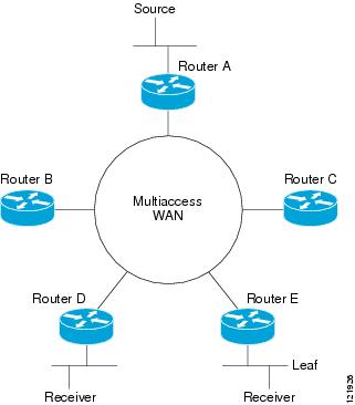
Traditionally, over NBMA networks, Cisco routers would perform a pseudobroadcast to get broadcast or multicast packets to all neighbors on a multiaccess network. For example, assume in Figure 1 that Routers A, B, C, D, and E were running the Open Shortest Path First (OSPF) protocol. Router A must deliver to Routers D and E. When Router A sends an OSPF Hello packet, the data link layer replicates the Hello packet and sends one to each neighbor (this procedure is known as pseudobroadcast), which results in four copies being sent over the link from Router A to the multiaccess WAN.
Figure 1 Environment for IP Multicast over ATM Point-to-Multipoint VCs
With the advent of IP multicast, where high-rate multicast traffic can occur, the pseudobroadcast approach does not scale. Furthermore, in the preceding example, Routers B and C would get data traffic they do not need. To handle this problem, PIM can be configured in NBMA mode using the ip pim nbma-mode command. PIM in NBMA mode works only for sparse mode groups. Configuring PIM in NBMA mode would allow only Routers D and E to get the traffic without distributing to Routers B and C. However, two copies are still delivered over the link from Router A to the multiaccess WAN.
If the underlying network supported multicast capability, the routers could handle this situation more efficiently. If the multiaccess WAN were an ATM network, IP multicast could use multipoint VCs.
To configure IP multicast using multipoint VCs, Routers A, B, C, D, and E in Figure 1 must run PIM sparse mode. If the Receiver directly connected to Router D joins a group and Router A is the PIM RP, the following sequence of events occurs:
1.
2.
3.
4.
5.
If a host sends an IGMP report over an ATM interface to a router, the router adds the host to the multipoint VC for the group.
This feature can also be used over ATM subinterfaces.
Idling Policy for ATM VCs Created by PIM
An idling policy uses the ip pim vc-count command to limit the number of VCs created by PIM. When the router stays at or below the number configured, no idling policy is in effect. When the next VC to be opened will exceed the value, an idling policy is exercised. An idled VC does not mean that the multicast traffic is not forwarded; the traffic is switched to VC 0. VC 0 is the broadcast VC that is open to all neighbors listed in the map list. The name VC 0 is unique to PIM and the mroute table.
How the Idling Policy Works
The idling policy works as follows:
•
•
•
•
•
•
•
Keeping VCs from Idling
By default, all VCs are eligible for idling. You can configure a minimum rate required to keep VCs from being idled.
How to Configure IP Multicast over ATM Point-to-Multipoint VCs
•
Configuring IP Multicast over ATM Point-to-Multipoint VCs
Perform this task to configure IP multicast over ATM point-to-multipoint VCs. All of the steps in the task can be used in an ATM network. This feature can also be used over ATM subinterfaces. PIM NBMA mode could be used in an ATM, Frame Relay, SMDS, PRI ISDN, or X.25 network.
SUMMARY STEPS
1.
2.
3.
4.
5.
6.
7.
8.
9.
DETAILED STEPS
Configuration Examples for IP Multicast over ATM Point-to-Multipoint VCs
•
IP Multicast over ATM Point-to-Multipoint VCs: Example
The following example shows how to enable IP multicast over ATM point-to-multipoint VCs:
interface ATM2/0ip address 171.69.214.43 255.255.255.248ip pim sparse-modeip pim multipoint-signallingip ospf network broadcastatm nsap-address 47.00918100000000410B0A1981.333333333333.00atm pvc 1 0 5 qsaalatm pvc 2 0 16 ilmiatm multipoint-signallingmap-group mpvcrouter ospf 9network 171.69.214.0 0.0.0.255 area 0!ip classlessip pim rp-address 171.69.10.13 98!map-list mpvcip 171.69.214.41 atm-nsap 47.00918100000000410B0A1981.111111111111.00 broadcastip 171.69.214.42 atm-nsap 47.00918100000000410B0A1981.222222222222.00 broadcastip 171.69.214.43 atm-nsap 47.00918100000000410B0A1981.333333333333.00 broadcastAdditional References
Related Documents
IP multicast commands
Configuring ATM for point-to-multipoint signaling
MIBs
None
To locate and download MIBs for selected platforms, Cisco IOS releases, and feature sets, use Cisco MIB Locator found at the following URL:
Technical Assistance
Feature Information for Configuring IP Multicast over ATM Point-to-Multipoint VCs
Table 1 lists the features in this module and provides links to specific configuration information. Only features that were introduced or modified in Cisco IOS Releases 12.2(1) or 12.0(3)S or later appear in the table.
Not all commands may be available in your Cisco IOS software release. For details on when support for specific commands was introduced, see the command reference documents.
If you are looking for information on a feature in this technology that is not documented here, see the "IP Multicast Features Roadmap".
Cisco IOS software images are specific to a Cisco IOS software release, a feature set, and a platform. Use Cisco Feature Navigator to find information about platform support and Cisco IOS software image support. Access Cisco Feature Navigator (http://www.cisco.com/go/fn). You must have an account on Cisco.com. If you do not have an account or have forgotten your username or password, click Cancel at the login dialog box and follow the instructions that appear.
Note
Table 1 Feature Information for IP Multicast over ATM Point-to-Multipoint VCs
Any Internet Protocol (IP) addresses used in this document are not intended to be actual addresses. Any examples, command display output, and figures included in the document are shown for illustrative purposes only. Any use of actual IP addresses in illustrative content is unintentional and coincidental.
© 2007 Cisco Systems, Inc. All rights reserved.